EP4568016A1 - Wanderwellenantenne und vorrichtung mit einer solchen antenne - Google Patents
Wanderwellenantenne und vorrichtung mit einer solchen antenne Download PDFInfo
- Publication number
- EP4568016A1 EP4568016A1 EP23307142.2A EP23307142A EP4568016A1 EP 4568016 A1 EP4568016 A1 EP 4568016A1 EP 23307142 A EP23307142 A EP 23307142A EP 4568016 A1 EP4568016 A1 EP 4568016A1
- Authority
- EP
- European Patent Office
- Prior art keywords
- antenna
- main direction
- undulation
- traveling wave
- length
- Prior art date
- Legal status (The legal status is an assumption and is not a legal conclusion. Google has not performed a legal analysis and makes no representation as to the accuracy of the status listed.)
- Pending
Links
Images

Classifications
-
- H—ELECTRICITY
- H01—ELECTRIC ELEMENTS
- H01Q—ANTENNAS, i.e. RADIO AERIALS
- H01Q13/00—Waveguide horns or mouths; Slot antennas; Leaky-waveguide antennas; Equivalent structures causing radiation along the transmission path of a guided wave
- H01Q13/08—Radiating ends of two-conductor microwave transmission lines, e.g. of coaxial lines, of microstrip lines
- H01Q13/085—Slot-line radiating ends
Definitions
- the present invention relates to a traveling wave antenna. It also relates to a device equipped with such an antenna.
- the field of the invention is the field of traveling wave antennas.
- Traveling wave antennas have a flared structure that allows them to be properly tuned over a wide frequency band.
- One example is the Vivaldi antenna, designed by Gibson in 1979.
- a traveling wave antenna has a planar structure made of one or more layers. It has an opening formed between two metal parts that can be on the same layer, or on different layers in the case of a multi-layer antenna.
- the opening between the two metal parts, and forming the antenna extends in a main direction, also corresponding to the direction of the length of the antenna. This opening has a width that increases in said main direction, for example according to an exponential opening.
- This topology has many advantages, including its wide bandwidth with constant gain, the possibility of having a directional diagram, its ease of production as well as a low cost, making it interesting for radar, 5G, ultra-wideband or millimeter applications.
- this topology has a major drawback which is the length of the antenna. Indeed, traveling wave antennas have significant lengths limiting their compactness and making their integration bulky.
- An aim of the present invention is to remedy at least one of the aforementioned drawbacks.
- Another aim of the present invention is to propose a solution for reducing the length of a traveling wave antenna.
- the invention proposes to undulate the antenna along the main direction in which the aperture of the antenna extends, this direction also corresponding to the direction of the length of the traveling wave antenna.
- this direction also corresponding to the direction of the length of the traveling wave antenna.
- the inventors have noticed that undulating the traveling wave antenna in the direction of its length has little or no impact on the general operation of the antenna, in particular at the bottom of the band. Furthermore, as will be described later, the undulation profile, and in particular the number of undulations and/or the width of the undulation pattern, makes it possible to adjust certain characteristics of the traveling wave antenna according to the invention, making it more suitable for different applications, compared to prior art antennas having a planar shape.
- planar structure is meant a structure having a negligible thickness compared to its width and length.
- traveling wave antennas are made in the form of one or more layers of negligible thicknesses, compared to their widths and lengths. It should be noted that the traveling wave antenna according to the invention is not planar since it comprises at least one undulation pattern. In other words, the traveling wave antenna comprises a planar structure which is undulated in the main direction.
- undulation pattern is meant a movement which rises and then falls relative to the general plane of the planar structure, i.e. relative to the plane formed by the planar structure.
- the undulation of the antenna according to the invention is not necessarily alternating and may be formed only on one side of the planar structure. Alternatively, the undulation of the antenna according to the invention may be alternating and extend from one side and then the other of the planar structure.
- profile of the antenna is meant the appearance of the edge of said antenna extending in said main direction.
- the antenna according to the invention is undulated in the main direction to obtain one or more undulations.
- Each undulation extends, in said antenna, in a direction perpendicular to the main direction.
- the antenna according to the invention may be undulated over only part of its length in the main direction.
- the antenna has a wavy profile over only part of its length in the main direction.
- Such an antenna can be made in a simple way, although the reduction in the total length of the antenna in the main direction will be limited.
- the antenna according to the invention can be undulated only on at least part, or all, of its excitation part.
- the antenna according to the invention may be undulated only on at least part, or all, of its radiating part.
- the antenna according to the invention can be undulated over the majority of, and in particular over 90% of, and even more particularly over all, of its length in the main direction.
- At least one wave pattern may have a profile, or section, of any other shape, for example triangular, square, rectangular, etc.
- the antenna according to the invention may comprise a single undulation pattern.
- the length of the corrugated part of the antenna it is possible to adjust the length of the corrugated part of the antenna.
- the inventors have noticed that by increasing the width of the ripple pattern in the main direction, in particular when the ripple pattern is a cylindrical pattern or has a semi-circular profile, it is possible to depoint the behavior of said antenna, in comparison to a planar antenna not comprising a ripple pattern. In other words, the response of the antenna thus obtained is depointed compared to a planar antenna not comprising a ripple.
- the depointing follows the direction in which the ripple is formed and will be more or less significant depending on the width, and in particular the diameter, of the ripple pattern.
- the traveling wave antenna according to the invention can comprise several undulation patterns.
- the presence of several undulation patterns in the antenna according to the invention makes it possible to reduce the total length occupied by the antenna, in the main direction. For a given undulation pattern, the greater the number of undulation patterns, the smaller the total length of the antenna in the main direction.
- the wave patterns may not be alternating.
- the ripple patterns are formed on the same side of the antenna face.
- This embodiment makes it possible to reduce the total length of the antenna according to the invention in the main direction, while limiting the thickness of the antenna.
- the traveling wave antenna according to the invention may comprise alternating undulation patterns.
- the alternating ripple patterns are formed on either side of the antenna, i.e. on the side of each of the faces of the antenna alternately.
- This embodiment makes it possible to further reduce the total length of the antenna according to the invention in the main direction, while increasing the thickness of the antenna.
- the ripple patterns may have an identical amplitude, in particular in a direction perpendicular to the main direction.
- the "amplitude" of a ripple pattern is the actual amplitude, that is, the absolute value of the amplitude of the ripple pattern, without taking into account the direction of the ripple pattern.
- "amplitude” is the absolute value of the maximum height of the ripple pattern.
- the ripple patterns may have an amplified or dampened amplitude, in the main direction.
- the amplitude of the ripple patterns may increase, gradually or discretely, in the main direction, in the direction of increasing the width of the opening.
- the amplitude of the ripple patterns may decrease, gradually or discretely, in the main direction in the direction of increasing the width of the opening.
- the amplitude of the ripple patterns may increase, respectively decrease, then decrease, respectively increase, in the main direction, in the direction of increasing the width of the opening.
- the antenna according to the invention can be obtained by folding a plane traveling wave antenna in a mold.
- planar traveling wave antenna is obtained, in accordance with the state of the art.
- This planar antenna is then deformed, or folded, in a mold or in a machine provided for this purpose, to obtain at least one undulation pattern in the main direction.
- Folding can be achieved by deformation.
- Folding can be done by thermoforming.
- the traveling wave antenna according to the invention can be produced by printing, and in particular by hydrographic printing, on a substrate having a corrugated surface.
- the layer(s) forming the antenna are deposited directly onto the substrate by printing and the at least one ripple pattern is formed at the same time as the printing of the antenna.
- a traveling wave antenna, and in particular a Vivaldi traveling wave antenna, according to the invention can be obtained by undulating a planar structure.
- the patterns and gains are similar between a corrugated antenna according to the invention and a planar antenna according to the state of the art, up to a certain frequency depending on the corrugation. From this frequency the radiation pattern changes and cross-polarization becomes the majority because an electric field is formed between the corrugation peaks.
- the antenna's elevation pattern is less directional at certain frequencies.
- a Vivaldi antenna made from a 10 cm planar structure comprising 2 cylindrical corrugations (2 half-cylinders) with a diameter of 25 mm
- the opening of the elevation pattern is wider between 4.4 GHz and 6.8 GHz.
- An antenna according to the invention may be a Vivaldi antenna, an antipodal Vivaldi antenna, or a balanced antipodal Vivaldi antenna, or any other type of traveling wave antenna.
- the device according to the invention can be a wave receiver.
- the device according to the invention may be a wave transmitter
- the device according to the invention can be used for ultra-wideband applications, 5G applications, radar-type applications.
- the device according to the invention can be used for ultra-wideband (UWB) radar applications, UWB wireless communications, direction finding, etc. More generally, the device according to the invention can be used for all applications using traveling wave antennas.
- UWB ultra-wideband
- UWB wireless communications UWB wireless communications
- direction finding etc.
- the device according to the invention can be used for all applications using traveling wave antennas.
- variants of the invention comprising only a selection of characteristics described below isolated from the other characteristics described, if this selection of characteristics is sufficient to confer a technical advantage or to differentiate the invention compared to the state of the prior art.
- This selection includes at least one preferably functional characteristic without structural details, or with only a part of the structural details if this part is only sufficient to confer a technical advantage or to differentiate the invention compared to the state of the prior art.
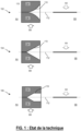
- FIGURE 1 is a schematic representation of non-limiting exemplary embodiments of traveling wave antennas according to the state of the art.
- FIGURE 1 shows a representation of three prior art traveling wave antennas 102-106.
- Each antenna 102-106 is shown in a top view AA indicated by the dotted arrow in the side view, and in a side view BB, also called a profile view, indicated by a solid arrow in the top view AA.
- Each antenna 102-106 may be made in the form of a single layer. Alternatively, each antenna 102-106 may be made in the form of several layers arranged on the same face or on different faces in the case, for example, of an antipodal antenna. Generally, each antenna 102-106 may be a Vivaldi antenna, an antipodal Vivaldi antenna, or a balanced antipodal Vivaldi antenna.
- Each antenna 102-106 has an opening 110, extending in a direction 112, called the main direction.
- This main direction 112 corresponds to the direction of the length of the antenna.
- the opening 110 is formed between at least two conductive areas 114 and 116.
- Each conductive area 114-116 may be made of any electrically conductive material, for example copper.
- the conductive areas 114-116 may be located on the same layer or on different layers stacked on top of each other.
- the shape of the conductive areas 114-116 is not limited to that shown in the FIGURE 1 .
- the opening 110 is an essential element of the antenna. It extends along the main direction 120.
- the width of the opening 110 increases in the main direction 112 so that the opening has a narrow end and a wide end.
- the width of the opening 110 increases progressively according to an exponential growth.
- the width of the opening increases progressively according to a linear growth.
- the width of the opening increases progressively according to a linear growth over a portion of the length of the antenna 106 in the main direction, then remains constant thereafter.
- these examples are given for information purposes only and are in no way limiting.
- a state-of-the-art traveling wave antenna has a planar shape.
- the profile of the antenna is rectilinear as shown in the FIGURE 1 for each of the antennas 102-106.
- each antenna 102-106 forms a plane, or has a rectilinear slice.
- the thickness of the antenna is negligible compared to the width and length of the antenna, the latter of which may differ depending on the application in which the antenna is used.
- the prior art planar wave antenna may have a thickness of about a hundred ⁇ m, while the length of the antenna may be up to 10cm in the main direction 112.
- FIGURE 2 is a schematic representation of a non-limiting exemplary embodiment of a traveling wave antenna according to the invention.
- Antenna 200 of the FIGURE 2 is represented in a side profile view.
- the FIGURE 2 shows the edge of the antenna 200.
- Antenna 200 of the FIGURE 2 includes all the characteristics of a state-of-the-art traveling wave antenna, and in particular of any of the antennas 102-106 of the FIGURE 1 .
- the 200 antenna of the FIGURE 2 is wavy in the main direction 112, so that its profile has several wavy patterns.
- the antenna 200 comprises 10 cylindrical undulations 202.
- each undulation corresponds to a half-cylinder extending in the direction perpendicular to the main direction 112.
- Each undulation 202 forms, in the profile of the antenna 200, a undulation pattern, in the form of a semicircle. In other words, each undulation 202 has a semicircle section.
- the antenna 200 comprises alternating undulation patterns formed on either side of the antenna 200, that is to say on the side of each face of the antenna 200.
- the antenna 200 is in the form of a planar structure undulating in the main direction 112.
- each corrugation has a width of 5 mm and the antenna 200 comprises 10 alternating corrugations.
- the total length LA of the antenna is 8.4 cm for a linear length of the planar structure of 10 cm (unfolded length).
- the antenna 200 has a length that is 16% shorter than a planar antenna of the prior art.
- the length reduction indicated above gives the value actually measured in a particular case. In theory, the length reduction can reach 27%.
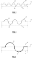
- FIGURE 3 is a schematic representation of another non-limiting exemplary embodiment of a traveling wave antenna according to the invention.
- Antenna 300 of the FIGURE 3 is represented in a side profile view.
- the FIGURE 3 shows the edge of the antenna 300.
- Antenna 300 of the FIGURE 3 includes all the characteristics of a state-of-the-art traveling wave antenna, and in particular of any of the antennas 102-106 of the FIGURE 1 .
- the 300 antenna of the FIGURE 3 is wavy in the main direction 112, so that its profile has several wavy patterns.
- the antenna 300 comprises 5 cylindrical undulations 302.
- each undulation 302 corresponds to a half-cylinder extending in the direction perpendicular to the main direction 112.
- Each undulation 302 forms, in the profile of the antenna 300, a wave pattern, in the form of a semicircle. In other words, each undulation 302 has a semicircle section.
- the antenna 300 comprises alternating undulation patterns formed on either side of the antenna 300, that is to say on the side of each face of the antenna 300.
- the antenna 300 is in the form of a planar structure undulating in the main direction 112.
- each corrugation 302 has a width of 10 mm and the antenna 300 comprises 5 alternating corrugations.
- the total length LA of the antenna is 7.5 cm for a linear length of the planar structure of 10 cm (unfolded length).
- the antenna 300 has a length 25% shorter than a planar antenna of the prior art.
- FIGURE 4 is a schematic representation of another non-limiting exemplary embodiment of a traveling wave antenna according to the invention.
- the 400 antenna of the FIGURE 4 is represented in a side profile view. In other words, the FIGURE 4 shows the edge of the 400 antenna.
- the 400 antenna of the FIGURE 4 includes all the characteristics of a state-of-the-art traveling wave antenna, and in particular of any of the antennas 102-106 of the FIGURE 1 .
- the 400 antenna of the FIGURE 4 is wavy in the main direction 112, so that its profile has several wavy patterns.
- the antenna 400 comprises 2 cylindrical corrugations 402.
- each corrugation 302 corresponds to a half-cylinder extending in the direction perpendicular to the main direction 112.
- Each corrugation 402 forms, in the profile of the antenna 400, a corrugation pattern, in the form of a semicircle. In other words, each corrugation 402 has a semicircle section.
- the antenna 400 comprises alternating undulation patterns formed on either side of the antenna 400, that is to say on the side of each face of the antenna 400.
- the antenna 400 is in the form of a planar structure undulating in the main direction 112.
- each corrugation 402 has a width of 25 mm and the antenna 400 comprises 2 alternative corrugations.
- the total length LA of the antenna is 7.3 cm for a linear length of the planar structure of 10 cm (unfolded length).
- the antenna 400 has a length 27% shorter than a planar antenna of the state of the art.
- FIGURE 5 is a schematic representation of another non-limiting exemplary embodiment of a traveling wave antenna according to the invention.
- Antenna 500 of the FIGURE 5 is represented in a side profile view.
- the FIGURE 5 shows the edge of the 500 antenna.
- Antenna 500 of the FIGURE 5 includes all the characteristics of a state-of-the-art traveling wave antenna, and in particular of any of the antennas 102-106 of the FIGURE 1 .
- the 500 antenna of the FIGURE 5 is wavy in the main direction 112.
- the antenna 500 comprises a single cylindrical corrugation 502.
- the corrugation 502 corresponds to a half-cylinder extending in the direction perpendicular to the main direction 112.
- the corrugation 502 forms, in the profile of the antenna 500, a corrugation pattern, in the form of a semicircle.
- the corrugation 502 has a semicircular section.
- the antenna 500 is in the form of a planar structure undulating in the main direction 112.
- the corrugation 502 has a width of 50 mm.
- the total length LA of the antenna is 7.3 cm for a linear length of the planar structure of 10 cm (unfolded length).
- the antenna 500 has a length 27% shorter than a planar antenna of the state of the art.
- each antenna is corrugated using a cylindrical corrugation, that is to say one whose section is in the shape of a semicircle.
- the invention is not limited to an antenna comprising cylindrical corrugations, and other forms of corrugation can be used, such as for example corrugations of elliptical, triangular, square, rectangular, sinusoidal section, etc.
- FIGURE 6 is a schematic representation of another non-limiting exemplary embodiment of a traveling wave antenna according to the invention.
- Antenna 600 of the FIGURE 6 includes all the characteristics of a state-of-the-art traveling wave antenna, and in particular of any of the antennas 102-106 of the FIGURE 1 .
- the 600 antenna of the FIGURE 6 is wavy in the main direction 112, so that its profile has several wavy patterns.
- the antenna 600 comprises 6 amplified sinusoidal ripples such that the amplitude of the ripples increases in the main direction, in the direction in which the width of the antenna aperture increases.
- the antenna 600 comprises alternating undulation patterns formed on either side of the antenna 600, that is to say on the side of the two faces of the antenna 600.
- the antenna 600 is in the form of a planar structure undulating sinusoidally in the main direction 112.
- the total length LA of the antenna is 7.5 cm for a linear length of the planar structure of 10 cm (unfolded length).
- the antenna 600 has a length 25% shorter than a planar antenna of the state of the art.
- FIGURE 7 is a schematic representation of another non-limiting exemplary embodiment of a traveling wave antenna according to the invention.
- Antenna 700 of the FIGURE 7 is represented in a side profile view.
- the FIGURE 7 shows the edge of the 700 antenna.
- Antenna 700 of the FIGURE 7 includes all the characteristics of a state-of-the-art traveling wave antenna, and in particular of any of the antennas 102-106 of the FIGURE 1 .
- the 700 antenna of the FIGURE 7 is wavy in the main direction 112, so that its profile has several wavy patterns.
- the antenna 700 comprises ten (10) cylindrical corrugations 702.
- each corrugation 702 corresponds to a half-cylinder extending in the direction perpendicular to the main direction 112.
- Each corrugation 702 forms, in the profile of the antenna 400, a corrugation pattern, in the form of a semicircle. In other words, each corrugation 702 has a semicircle section.
- the antenna 700 comprises undulation patterns which are not alternating, and which are formed only on one side of the antenna 700, that is to say on the side of the same face of the antenna 700.
- the antenna 700 is in the form of a planar structure undulating in the main direction 112.
- the patterns and gains are similar between a corrugated antenna according to the invention and a planar antenna according to the state of the art, up to a certain frequency which depends on the corrugation. From this frequency, the radiation pattern changes and cross-polarization becomes predominant because an electric field is formed between the corrugation peaks.
- the antenna's elevation diagram is less directional at certain frequencies.
- a Vivaldi antenna made from a 10 cm planar structure comprising 2 cylindrical corrugations with a diameter of 25 mm, i.e. the 400 antenna of the FIGURE 4
- the opening of the elevation diagram is wider between 4.4 and 6.8 GHz.
- the corrugated antenna has an offset of approximately 35° compared to a planar antenna, and this over the entire frequency band.
- the antenna according to the invention may be any type of traveling wave antenna, for example a traveling wave antenna of the Vivaldi, antipodal Vivaldi, or balanced antipodal Vivaldi type.
- the opening of the antenna may be of any shape, the or each conductive zone between which the opening of the antenna is formed may be of any shape.
- Each of the antennas 200, 300, 400, 500, 600 and 700, and in particular a corrugated traveling wave antenna according to the invention, can be obtained by different techniques.
- each of the antennas 200, 300, 400, 500, 600 and 700, and in particular a corrugated traveling wave antenna according to the invention can be produced by printing, and in particular by hydrographic printing, on a substrate/support having a corrugated surface according to the desired corrugation profile.
- the layer(s) forming the antenna are deposited directly on the substrate by printing and the at least one corrugation pattern is formed at the same time as the printing of the antenna.
Landscapes
- Aerials With Secondary Devices (AREA)
Priority Applications (1)
| Application Number | Priority Date | Filing Date | Title |
|---|---|---|---|
| EP23307142.2A EP4568016A1 (de) | 2023-12-06 | 2023-12-06 | Wanderwellenantenne und vorrichtung mit einer solchen antenne |
Applications Claiming Priority (1)
| Application Number | Priority Date | Filing Date | Title |
|---|---|---|---|
| EP23307142.2A EP4568016A1 (de) | 2023-12-06 | 2023-12-06 | Wanderwellenantenne und vorrichtung mit einer solchen antenne |
Publications (1)
| Publication Number | Publication Date |
|---|---|
| EP4568016A1 true EP4568016A1 (de) | 2025-06-11 |
Family
ID=90105157
Family Applications (1)
| Application Number | Title | Priority Date | Filing Date |
|---|---|---|---|
| EP23307142.2A Pending EP4568016A1 (de) | 2023-12-06 | 2023-12-06 | Wanderwellenantenne und vorrichtung mit einer solchen antenne |
Country Status (1)
| Country | Link |
|---|---|
| EP (1) | EP4568016A1 (de) |
Citations (4)
| Publication number | Priority date | Publication date | Assignee | Title |
|---|---|---|---|---|
| GB1601441A (en) * | 1978-03-10 | 1981-10-28 | Philips Electronic Associated | Antenna |
| US20050012672A1 (en) * | 2001-08-24 | 2005-01-20 | Fisher James Joseph | Vivaldi antenna |
| FR2903235A1 (fr) * | 2006-06-28 | 2008-01-04 | Thomson Licensing Sas | Perfectionnement aux antennes a rayonnement longitudinal de type fente |
| US8466846B1 (en) * | 2010-09-29 | 2013-06-18 | Rockwell Collins, Inc. | Ultra wide band balanced antipodal tapered slot antenna and array with edge treatment |
-
2023
- 2023-12-06 EP EP23307142.2A patent/EP4568016A1/de active Pending
Patent Citations (4)
| Publication number | Priority date | Publication date | Assignee | Title |
|---|---|---|---|---|
| GB1601441A (en) * | 1978-03-10 | 1981-10-28 | Philips Electronic Associated | Antenna |
| US20050012672A1 (en) * | 2001-08-24 | 2005-01-20 | Fisher James Joseph | Vivaldi antenna |
| FR2903235A1 (fr) * | 2006-06-28 | 2008-01-04 | Thomson Licensing Sas | Perfectionnement aux antennes a rayonnement longitudinal de type fente |
| US8466846B1 (en) * | 2010-09-29 | 2013-06-18 | Rockwell Collins, Inc. | Ultra wide band balanced antipodal tapered slot antenna and array with edge treatment |
Non-Patent Citations (1)
| Title |
|---|
| ACAR MEHMET AKIF ET AL: "3D Miniaturization Method and its Application to a Wearable Vivaldi Antenna", 2022 3RD URSI ATLANTIC AND ASIA PACIFIC RADIO SCIENCE MEETING (AT-AP-RASC), URSI, 30 May 2022 (2022-05-30), pages 1 - 4, XP034145061, DOI: 10.23919/AT-AP-RASC54737.2022.9814402 * |
Similar Documents
| Publication | Publication Date | Title |
|---|---|---|
| EP1433223B1 (de) | Mehrband pifa-antenne | |
| EP3417507B1 (de) | Elektromagnetisch reflektierende platte mit metamaterialstruktur und miniaturantennenvorrichtung mit solch einer platte | |
| EP3840124B1 (de) | Leckwellenantenne mit afsiw-technologie | |
| CA2682273C (fr) | Antenne a resonateur equipe d'un revetement filtrant et systeme incorporant cette antenne | |
| FR2860927A1 (fr) | Antenne interne de faible volume | |
| FR2822301A1 (fr) | Antenne a bande elargie pour appareils mobiles | |
| EP1568104B1 (de) | Mehrfachstrahlantenne mit photonischem bandlückenmaterial | |
| EP0575211A1 (de) | Strahlerelement einer Antenne mit breitbandigem Durchlassbereich und aus derartigen Elementen bestehende Gruppenantenne | |
| EP1564842B1 (de) | Ultrabreitbandige Antenne | |
| FR2922687A1 (fr) | Antenne compacte a large bande. | |
| EP2095465A1 (de) | Einfach- oder mehrfach-frequenzantenne | |
| WO2005117208A1 (fr) | Antenne planaire à plots conducteurs à partir du plan de masse et/ou d'au moins un élément rayonnant, et procédé de fabrication correspondant. | |
| EP3469657A1 (de) | Breitbanddrahtantenne mit widerstandsmustern mit variablem widerstand | |
| EP1550182B1 (de) | Schlitzantenne mit photonischem bandlückenmaterial | |
| EP3063828B1 (de) | Unterwasser-funkfrequenzantenne | |
| EP1430566A1 (de) | Breitband- oder multibandantenne | |
| EP4568016A1 (de) | Wanderwellenantenne und vorrichtung mit einer solchen antenne | |
| EP3218961A1 (de) | Rekonfigurierbare kompakte antennenvorrichtung | |
| EP3485534B1 (de) | Steuerbare multifunktionelle frequenzselektive oberfläche | |
| EP1903636A1 (de) | Adaptive Breitbandantenne | |
| EP0991135B1 (de) | Selektive Antenne mit Frequenzumschaltung | |
| EP0929914B1 (de) | Hochfrequenzantenne | |
| FR3126818A1 (fr) | Système électromagnétique avec déviation angulaire du lobe principal de rayonnement d'une antenne | |
| EP0326498B1 (de) | Resonanzschaltung und Filter mit dergleichen | |
| EP2449629B1 (de) | Omnidirektionales kompaktes breitbandantennensystem mit zwei weitgehend entkoppelten separaten übertragungs- und empfangszugangsleitungen |
Legal Events
| Date | Code | Title | Description |
|---|---|---|---|
| PUAI | Public reference made under article 153(3) epc to a published international application that has entered the european phase |
Free format text: ORIGINAL CODE: 0009012 |
|
| STAA | Information on the status of an ep patent application or granted ep patent |
Free format text: STATUS: THE APPLICATION HAS BEEN PUBLISHED |
|
| AK | Designated contracting states |
Kind code of ref document: A1 Designated state(s): AL AT BE BG CH CY CZ DE DK EE ES FI FR GB GR HR HU IE IS IT LI LT LU LV MC ME MK MT NL NO PL PT RO RS SE SI SK SM TR |
|
| STAA | Information on the status of an ep patent application or granted ep patent |
Free format text: STATUS: REQUEST FOR EXAMINATION WAS MADE |
|
| 17P | Request for examination filed |
Effective date: 20250919 |