EP4568036A1 - Collier de serrage pour des marchandises longitudinals - Google Patents
Collier de serrage pour des marchandises longitudinals Download PDFInfo
- Publication number
- EP4568036A1 EP4568036A1 EP24213040.9A EP24213040A EP4568036A1 EP 4568036 A1 EP4568036 A1 EP 4568036A1 EP 24213040 A EP24213040 A EP 24213040A EP 4568036 A1 EP4568036 A1 EP 4568036A1
- Authority
- EP
- European Patent Office
- Prior art keywords
- clamp
- long goods
- segment
- clamping
- clamp segment
- Prior art date
- Legal status (The legal status is an assumption and is not a legal conclusion. Google has not performed a legal analysis and makes no representation as to the accuracy of the status listed.)
- Pending
Links
Images


Classifications
-
- H—ELECTRICITY
- H02—GENERATION; CONVERSION OR DISTRIBUTION OF ELECTRIC POWER
- H02G—INSTALLATION OF ELECTRIC CABLES OR LINES, OR OF COMBINED OPTICAL AND ELECTRIC CABLES OR LINES
- H02G3/00—Installations of electric cables or lines or protective tubing therefor in or on buildings, equivalent structures or vehicles
- H02G3/30—Installations of cables or lines on walls, floors or ceilings
- H02G3/32—Installations of cables or lines on walls, floors or ceilings using mounting clamps
-
- F—MECHANICAL ENGINEERING; LIGHTING; HEATING; WEAPONS; BLASTING
- F16—ENGINEERING ELEMENTS AND UNITS; GENERAL MEASURES FOR PRODUCING AND MAINTAINING EFFECTIVE FUNCTIONING OF MACHINES OR INSTALLATIONS; THERMAL INSULATION IN GENERAL
- F16L—PIPES; JOINTS OR FITTINGS FOR PIPES; SUPPORTS FOR PIPES, CABLES OR PROTECTIVE TUBING; MEANS FOR THERMAL INSULATION IN GENERAL
- F16L3/00—Supports for pipes, cables or protective tubing, e.g. hangers, holders, clamps, cleats, clips, brackets
- F16L3/08—Supports for pipes, cables or protective tubing, e.g. hangers, holders, clamps, cleats, clips, brackets substantially surrounding the pipe, cable or protective tubing
- F16L3/10—Supports for pipes, cables or protective tubing, e.g. hangers, holders, clamps, cleats, clips, brackets substantially surrounding the pipe, cable or protective tubing divided, i.e. with two members engaging the pipe, cable or protective tubing
- F16L3/1066—Supports for pipes, cables or protective tubing, e.g. hangers, holders, clamps, cleats, clips, brackets substantially surrounding the pipe, cable or protective tubing divided, i.e. with two members engaging the pipe, cable or protective tubing with three or more members surrounding the pipe
-
- F—MECHANICAL ENGINEERING; LIGHTING; HEATING; WEAPONS; BLASTING
- F16—ENGINEERING ELEMENTS AND UNITS; GENERAL MEASURES FOR PRODUCING AND MAINTAINING EFFECTIVE FUNCTIONING OF MACHINES OR INSTALLATIONS; THERMAL INSULATION IN GENERAL
- F16B—DEVICES FOR FASTENING OR SECURING CONSTRUCTIONAL ELEMENTS OR MACHINE PARTS TOGETHER, e.g. NAILS, BOLTS, CIRCLIPS, CLAMPS, CLIPS OR WEDGES; JOINTS OR JOINTING
- F16B2/00—Friction-grip releasable fastenings
- F16B2/02—Clamps, i.e. with gripping action effected by positive means other than the inherent resistance to deformation of the material of the fastening
- F16B2/06—Clamps, i.e. with gripping action effected by positive means other than the inherent resistance to deformation of the material of the fastening external, i.e. with contracting action
- F16B2/10—Clamps, i.e. with gripping action effected by positive means other than the inherent resistance to deformation of the material of the fastening external, i.e. with contracting action using pivoting jaws
-
- F—MECHANICAL ENGINEERING; LIGHTING; HEATING; WEAPONS; BLASTING
- F16—ENGINEERING ELEMENTS AND UNITS; GENERAL MEASURES FOR PRODUCING AND MAINTAINING EFFECTIVE FUNCTIONING OF MACHINES OR INSTALLATIONS; THERMAL INSULATION IN GENERAL
- F16L—PIPES; JOINTS OR FITTINGS FOR PIPES; SUPPORTS FOR PIPES, CABLES OR PROTECTIVE TUBING; MEANS FOR THERMAL INSULATION IN GENERAL
- F16L3/00—Supports for pipes, cables or protective tubing, e.g. hangers, holders, clamps, cleats, clips, brackets
- F16L3/08—Supports for pipes, cables or protective tubing, e.g. hangers, holders, clamps, cleats, clips, brackets substantially surrounding the pipe, cable or protective tubing
- F16L3/10—Supports for pipes, cables or protective tubing, e.g. hangers, holders, clamps, cleats, clips, brackets substantially surrounding the pipe, cable or protective tubing divided, i.e. with two members engaging the pipe, cable or protective tubing
- F16L3/1008—Supports for pipes, cables or protective tubing, e.g. hangers, holders, clamps, cleats, clips, brackets substantially surrounding the pipe, cable or protective tubing divided, i.e. with two members engaging the pipe, cable or protective tubing with two members engaging the pipe, cable or tubing, both being made of thin band material completely surrounding the pipe
- F16L3/1025—Supports for pipes, cables or protective tubing, e.g. hangers, holders, clamps, cleats, clips, brackets substantially surrounding the pipe, cable or protective tubing divided, i.e. with two members engaging the pipe, cable or protective tubing with two members engaging the pipe, cable or tubing, both being made of thin band material completely surrounding the pipe the members being joined by quick-acting means
Definitions
- the invention relates to a long goods clamp with at least two clamp segments enclosing a long goods receptacle, which are connected to one another in an articulated manner, and with a tension lock comprising a tensioning element held in an articulated manner on one of the clamp segments, wherein the tensioning element engages behind a tensioning abutment located on the adjacent clamp segment when the long goods clamp is closed.
- long goods clamps are used, which are also referred to as cable clamps when fastening or fixing electrical cables as long goods.
- Such long goods clamps have at least two clamp segments, which enclose a long goods receptacle with their inner sides.
- the clamp segments have, for example, SE 1651019 A1 known, has a curved inner surface against which the long goods located in the long goods holder rests.
- the two clamp segments are pivotally connected to one another, so that one clamp segment can be pivoted relative to the other clamp segment, thereby opening the long goods holder or closing it when the long goods holder is open.
- a long goods clamp has a tension lock.
- One of the two clamp segments carries a tensioning element, for example a tension hook, while the other clamp segment has a tensioning abutment at its end, which is engaged by the tensioning element of the other clamp segment when the long goods clamp is closed.
- the tensioning element is connected to a tensioning lever, which is also carried by this clamp segment, and can be tensioned by it.
- Such a tension lock typically operates like an over-center clamp; thus, the tensioning lever of such a tension lock is secured in the closed position by an over-center position when the Clamp segments exert a pre-tensioning force in the radial direction on the long goods located in the long goods holder.
- Another long goods clamp is made of EP 3 835 638 A1
- This previously known long goods clamp has at least two clamp segments, each clamp segment consisting of a plastic clamping block and a clamping block holder.
- the clamping block holder is a sheet metal part providing a clamping block receptacle.
- the clamping block itself has a concave groove on its side facing the long goods receptacle, the cross-sectional curvature of which is adapted to the curvature of the long goods to be inserted into the long goods receptacle.
- the two clamp segments are articulated to one another to open and close the long goods receptacle.
- An over-center clamp lock is used to close the long goods receptacle and to clamp a long goods inserted therein.
- This previously known concept can also be used to provide a long goods clamp with a long goods receptacle in which three long goods, for example three electrical cables, can be positioned and clamped together to a mounting base.
- three long goods for example three electrical cables
- one of the two clamp segments carries two clamping blocks.
- the other clamp segment carries only one clamping block.
- the terminal blocks are designed in the manner of a prism with trapezoidal base surfaces.
- the aforementioned long goods clamps are adapted to the inner contour of the bearing support to the circumferential curvature of the long goods to be accommodated. This is desired to ensure the largest possible contact area between the clamping blocks and the outer surface of the long goods inserted into the bearing support.
- the object of the invention is to propose such a long goods clamp.
- a long goods clamp of the generic type mentioned at the outset in which the effective extension of at least one first clamp segment or of the clamping element can be adjusted with respect to its portion on the outer circumference of the long goods receptacle, wherein the adjustment of the effective extension of the first clamp segment relative to an adjacent second clamp segment takes place at the articulated connection with which the first clamp segment is articulatedly connected to the adjacent clamp segment.
- the effective extension of at least one clamp segment or the clamping element can be adjusted relative to an adjacent clamp segment.
- the effective extension of such a clamp segment is the extension that this clamp segment has in relation to its share of the outer circumference of the long goods holder.
- the effective extension of such a clamp segment is therefore that portion of this clamp segment with which this clamp segment limits the long goods receptacle in the radial direction outwards.
- the long goods receptacle is enclosed in this direction by the clamp segments and usually also by the clamping element bridging the distance between two adjacent clamp segments.
- the circumference of the long goods receptacle and thus its cross-sectional area or the receptacle volume can be made larger or smaller in proportion to the adjustability of the effective extension.
- the adjustability of such a clamp segment relative to an adjacent clamp segment takes place at the articulated connection with which this first clamp segment, whose effective extension can be adjusted, is connected to its neighboring clamp segment as a second quick-release segment.
- the advantage of this is that the articulated connection of the two clamp segments, with the pivot axis running parallel to the longitudinal axis of the long goods holder, can be used not only to open and close the long goods holder by pivoting these clamp segments against each other, but also in connection with an increase or reduction of its effective extension.
- the adjacent clamp segment is provided with a joint piece adjustable about its longitudinal axis for the intended articulated connection.
- This is typically a joint piece with a cylindrical outer surface.
- the joint piece itself can be designed as a joint rod or as a joint sleeve.
- This joint piece has a connection opening arranged transversely to its longitudinal axis providing the pivot axis, specifically for the connection of the other clamp segment.
- the other clamp segment or the clamping element has at least one connection pin. Such a connection pin penetrates the connection opening of the joint piece. This is typically straight.
- a curved design is also entirely possible.
- a setting mechanism is provided, by which the extraction movement of the connecting pin from the connection opening can be blocked.
- the setting mechanism is intended to block only one extraction movement of the connecting pin, thus a movement to increase the effective extension.
- the alignment mechanism is preferably designed in the manner of a snap-lock.
- a snap-lock by which the extension length of the connecting pin from the connection opening can be blocked in a specific position, can be designed in different ways.
- the connecting pin has a row of locking teeth on its outer surface extending in the direction of its longitudinal extent. Blocking can thus be carried out at any tooth position along the row of locking teeth.
- the locking teeth of such a row of locking teeth are typically designed asymmetrically, namely in such a way that the flat flank points in the insertion direction and the steep flank points opposite to the insertion direction and thus in the extraction direction.
- Such an alignment mechanism further has a locking element which, in its locked position, engages in an intermediate tooth position.
- Such a locking element has an engagement contour with which it, when engaged with the row of locking teeth, is supported on the short flank of a locking tooth of the row of locking teeth, thereby blocking any extraction movement of the connecting pin reaching through the connection opening.
- a preferred embodiment provides for the joint piece to be designed as a joint sleeve and the locking member to be arranged within the joint sleeve. This saves space.
- the joint sleeve provides the necessary guidance for the locking member.
- fewer parts are required to create the long goods clamp.
- the interior of the sleeve is used to accommodate a spring element or a spring element arrangement, by means of which the locking member is held in its engaged position in the ratchet row. is held in place.
- the locking member is held in place by an actuator, which can be used to push the locking member out of its engaged position in the row of locking teeth against the restoring force of the spring element or spring package.
- an actuator can be formed onto the locking member as an extension.
- This locking-actuating member then has an oblong hole-like opening whose long axis follows the longitudinal extent of the joint piece, so that the sliding movement in the axial direction of the joint piece can be carried out by pressing in the actuator. If a joint sleeve is used as the joint piece, this protrudes from the end face of the joint sleeve.
- such a clamp segment carries not just one connecting pin, but two connecting pins arranged parallel to one another.
- the joint piece also has two connecting openings spaced apart by the distance between the connecting pins.
- the adjustment mechanism is designed such that both connecting pins, each passing through a connecting opening, can be blocked with regard to their extraction movement from the connecting openings.
- such an adjustment mechanism also has two actuators for removing the extraction block.
- the two connecting pins make the adjustment of the effective extension more stable.
- a long item located therein is contacted by this clamp segment at several sections of its outer surface.
- the two connecting pins are formed as legs of a U-shaped, first clamp segment part.
- the web of such a clamp segment part connecting the two connecting pins is held on a second clamp segment part of this clamp segment, adjustable about its longitudinal axis.
- This not only allows for simple production of the clamp segment part providing the connecting pins, but also allows for the formation of an articulated connection between the two clamp segment parts. This, in turn, allows for better adaptation to the circumferential contour of one or more long items accommodated in the long goods holder.
- Such a web connecting the two connecting pins can be guided as a bearing web on a pivot bearing surface of the other clamp segment part.
- the pivot bearing surface is typically provided by a loop-like bend in the second clamp element part.
- a section extending in the circumferential extent will be double-layered. This can be used for various purposes.
- the inner layer facing the long goods holder is typically convexly curved in the circumferential direction of the long goods clamp to adapt to one or more long goods to be held therein.
- the double layer design of a clamp segment part of a clamp segment can be used to make the outer layer of the double layer straight and thus not curved, unlike the inner layer of the double layer.
- the double layer can be used, for example, to provide a more stable pivot bearing for a tensioning lever belonging to the clamping lock, since such a tensioning bearing can be formed with the participation of both layers.
- the double layer design of such a second clamp segment part can serve to form the tensioning abutment, for example designed as a tensioning hook.
- tensioning hooks for closing or tensioning the long goods clamp are engaged behind by a tensioning element and such a hook is inserted through a section of each layer of the double layer of this clamp segment part, thus thereby forming a pair of tensioning hooks is provided, with appropriate design of this second clamp segment part, tensioning can ensure that the contact surfaces of the two clamping hooks forming a pair of clamping hooks are aligned when a clamping force is exerted on the long goods located within the long goods receptacles by tightening the long goods clamp. This requires that when the long goods clamp is open, these clamping hook contact surfaces are not aligned with one another.
- the double layer in such a design is used to align the two layers to a certain extent in the clamping direction.
- the contact surfaces of the hooks can be aligned before the actual clamping force is exerted on the long goods located within the long goods receptacle.
- This transition between the two clamping stages can be felt haptically.
- the clamping force required on the long goods located in the long goods holder can be checked by tactilely noticing such a two-stage effect when the clamping fastener is closed.
- the long goods clamp can also be designed in such a way that, in a first step, the necessary clamping force is generated from the long goods located in the long goods holder and then the two layers are aligned with each other in the manner described above. Here, too, the transition between the two clamping stages can be felt haptically.
- the aforementioned double layer of the clamp segment forming the clamping abutment can also be used to create a detent through the relative movement of the two layers in the clamping direction. This detent closes when the desired clamping force is applied. Such engagement of the two complementary locking elements is also tactilely perceptible.
- such a long-goods clamp has three clamp segments, one of which is a base element.
- This base element has, for example, a trapezoidal cross-sectional profile.
- a clamp segment is pivotally connected to each of the two ends pointing in the circumferential direction of the long-goods holder.
- both connected clamp segments are adjustable in terms of their effective extension.
- a long goods clamp 1 is used to fasten one or more long goods to a fastening base, for example a shaft wall or in a Tower of a wind turbine.
- the long goods clamp 1 shown in the illustrated embodiment has three clamp segments, 2, 3, 4, and a clamping lock, identified overall by the reference numeral 5.
- the clamping lock 5 comprises a clamping element 6, which in the illustrated embodiment is designed in the form of a bow, a clamping lever 7, and a clamping abutment provided by two pairs of clamping hooks 8, 8.1.
- the pairs of clamping hooks 8, 8.1 belong to the clamp segment 4, while the clamping element 6 and the clamping lever 7 belong to the clamp segment 3.
- Figure 1 shows the long goods clamp 1 in its closed, tensioned position.
- the clamp segment 2 is a base segment, which in the illustrated embodiment has a trapezoidal cross-sectional geometry.
- the clamp segment 2 as the base segment is made from a sheet steel blank as a stamped and bent part.
- a screw head receptacle 11 with an opening is stamped into the base plate 10 of the clamp segment 2.
- the long goods clamp 1 can be attached to a mounting base by means of a screw fastener that extends through the opening.
- a long goods receptacle 12 is enclosed circumferentially by the clamp segments 2, 3, 4.
- the clamp segments 3, 4 are connected in an articulated manner, forming a joint loop 13 by a corresponding bend, the inside of which forms a pivot bearing surface for a joint sleeve 14 held therein.
- the joint sleeve 14 has a cylindrical outer surface.
- the joint loop 13 is formed by several individual joint loop strips spaced apart from one another in the direction of the longitudinal axis of the joint sleeve 14, which, with respect to the long goods receptacle 12, are reunited on the outside of a side wall formed onto the base plate 10 (see Figure 6 ).
- the clamp segment 3 is connected to the joint sleeve 14 by means of two connecting pins 15, 15.1, each of which passes through a connecting opening 16, 16.1 running transversely to its longitudinal extension.
- the connecting pins 15, 15.1 of the clamp segment 3 are part of a U-shaped first clamp segment part 18, made from a single piece of wire.
- the web 17 connecting the two connecting pins 15, 15.1 as the legs of this U-shaped clamp segment part 18 is pivotally connected about its longitudinal axis to a second clamp segment part 19 of the clamp segment 3.
- the second clamp segment part 19, made from a sheet steel plate, also has a hinged loop 20 provided in a bent portion, the inner side of which provides the pivot bearing surface for the web 17 of the first clamp segment part 18.
- clamp segment 4 is connected in the same way to clamp segment 2, which serves as the base segment.
- clamp segment 4 is also composed of two clamp segment parts.
- the legs 9, 9.1 of the clamping element 6 are also designed as connecting pins and extend through a joint sleeve 21 held by the clamping lever 7.
- the connecting pins of the legs 9, 9.1, like the connecting pins 15, 15.1, are fixed in the joint sleeve 21.
- the articulated connection of the clamping element 6 to the joint sleeve 21 and the connection of the first clamp segments 18 of the clamp segments 3, 4 to the respective joint sleeve 14 of the base segment are identical.
- the long goods clamp 1 not only has two clamp segments 3, 4 that are articulated relative to the clamp segment 2. Since the clamp segments 3, 4 in the illustrated embodiment are each divided into two clamp segments 18, 19, which in turn are articulated to one another, this allows a special adaptation of the contour of the inside of the clamp segments 3, 4 to one or more long goods to be accommodated and fastened in the long goods holder.
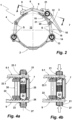
- the pivot axes of the components of the long goods clamp 1 that enclose the long goods holder 12 on the outside are in Figure 2 marked with the reference symbol S.
- the two clamp segments 3, 4, like the clamping element 6, can be adjusted relative to the adjacent clamp segment with regard to their effective extension and thus their share of the circumference of the long material holder 12. This is achieved by adjusting the connecting pins 15, 15.1 of the clamp segment 3 relative to the clamp segment 2. The same applies to the clamp segment 4 relative to the clamp segment 2 and the clamping element 6 relative to the clamp element 3. The adjustability is described below using the articulated connection of the clamping element 6 to the clamp element 3. The adjustability of the clamp segments 3, 4 relative to the clamp element 2, which serves as the base segment, is achieved in the same way.
- the sections of the legs 9, 9.1, which serve as connecting pins of the clamping element 6, extend through the articulated sleeve 21 held on the clamping lever 7.
- the clamping lever 7, in turn, is pivotably connected to the clamp element 3 as an over-center clamp. This means that when the clamping lever 7 is closed, the distance between the pivot axis of the articulated sleeve 21 and the center of the bearing mount 12 is less than the distance between the pivot axis of the clamping lever 7, and the two pivot axes are also spaced apart from one another in the circumferential direction, with the pivot axis of the clamping lever 7 being at a smaller distance from the clamping abutment than the pivot axis formed by the articulated sleeve 21.
- a row of locking teeth is provided (see Figure 4a ).
- the locking tooth rows are identified by the reference numerals 22, 22.1.
- the locking teeth of the locking tooth rows 22, 22.1 are asymmetrical.
- the flat flank points towards the clamping lever 7 and thus in the insertion direction of the legs 9, 9.1 with their connecting pin sections into the joint sleeve 21.
- the steep flank which in the illustrated embodiment runs at right angles to the longitudinal extent of the legs 9, 9.1, points in the opposite direction and thus in the extension direction in which the legs 9, 9.1 can be pulled out of the connection openings 23, 23.1 of the joint sleeve 21.
- Two locking members 24, 24.1 are arranged within the joint sleeve 21.
- a compression spring 25 is located between the locking members 24, 24.1. This spring is preloaded so that the spring force stored in the compression spring 25 pushes the locking members 24, 24.1 away from each other.
- the locking members 24, 24.1 are identically constructed.
- the locking member 24 is described below. The same specifications also apply to the locking member 24.1.
- the locking member 24 is adjustably guided within the joint sleeve 21 along its longitudinal extent and has a locking contour 26 on its end facing the row of locking teeth 22, with which the locking contour engages the row of locking teeth 22.
- the contour of the locking contour 26 corresponds to that of a tooth gap.
- a section of the locking contour 26 is supported on the short flank of a tooth. This blocks the extension movement of the leg 9 from the joint sleeve 21. However, the leg 9 can be inserted with its connecting pin section into the connecting opening 23.
- the locking member 24 is adjusted against the restoring force of the compression spring 25 within the joint sleeve 21.
- An actuator 27 is assigned to the locking member 24. This is also guided in the joint sleeve 21 and protrudes from the front of the joint sleeve 21.
- the actuator 27 in the illustrated embodiment is a plastic injection-molded part. The actuator 27 serves to cancel the Figure 4a shown blocking of an extension movement of the leg 9 relative to the joint sleeve 21.
- the actuator 27 which is supported with its end face located within the joint sleeve 21 on the locking member 24, the movement blocking, as in Figure 4b shown, is canceled. Adjustment of the clamping element 6 relative to the joint sleeve 21 is then readily possible, even to shorten its effective extension.
- the actuator 27 has an opening 28 provided transversely to its direction of movement, through which the leg 9 extends with its connecting pin section. This opening 28 is in the Figure 3 due to the perspective of the actuator 27, it can be seen from another actuator 27.1. This opening is identified by the reference numeral 28. Due to this measure, the actuator 27 is a captive part of the adjustment mechanism for adjusting the effective extension of the clamping element 6. As shown in Figure 3 As can be seen, the end face of the actuator 27 facing the locking member 24 is inclined and supported on the longer flank of the locking contour 26.
- the exploded view of the Figure 3 also illustrates the connection of the first U-shaped clamp segment part 18 with its connecting pins 15, 15.1 to the second clamp segment part 19.
- the second clamp segment part 19 carries two outwardly projecting bearing blocks 29, 29.1, to which the tensioning lever 7 is pivotally connected by means of a bearing pin 30.
- the result of the loop-like design of the receptacle for the web 17 of the first clamp segment part 18 is that the second clamp segment part 19, made from a sheet metal blank, is at least partially double-layered.
- the inner layer 31, facing the long goods receptacle 12, is concavely curved to adapt to the curved surface of a long goods to be accommodated therein (see also Figure 2 ).
- the outer layer 32 is designed to be non-curved.
- the bearing blocks 29, 29.1 are located at the end of the second clamp segment part 19 opposite the clamp segment part 18. These are provided by a section from each layer 31, 32, so that each Bearing block 29, 29.1 is ultimately formed from a pair of bearing blocks. Thus, the clamping force transmitted via the clamping lever 7 is equally transmitted to both layers 31, 32 of the second segment part 19.
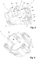
- the design of the two bearing blocks 29, 29.1 as clamping block pairs is in Figure 5 visible.
- the two inner clamping block parts are provided by the outer layer 32, while the two outer clamping block parts are formed from the inner layer 31.
- the clamp segment 4 which is constructed in the same way as the clamp segment 3, also has a double-layered clamp segment part 33.
- This clamp segment part 33 carries the clamping hook pairs 8, 8.1 at its ends.
- Each clamping hook pair 8, 8.1 is formed by a clamping hook part of the outer layer 34 and the inner layer 35.
- the contact surfaces on which the part of the clamping element engaging behind the clamping hook pairs 8, 8.1 rests, of each clamping hook part of a clamping hook pair 8, 8.1 are aligned with each other.
- the second clamp segment part 33 of the clamp segment 4 in such a way that, when the clamping lock is not tensioned, the contact surfaces on which the clamping element 6 rests with its web 36 are not aligned with each other, namely in such a way that that the clamping hook parts provided by the upper layer 34 are slightly offset in the opening direction of the clamping lock 5 compared to those of the lower layer 35.
- the upper layer 34 is thus adjusted in the tensioning direction relative to the lower layer until the Figure 5 shown position of the clamping hook parts of each clamping hook pair 8, 8.1 is reached.
- this position is additionally indicated haptically by a detent.
- a detent extension 37 is formed on the lower layer, which has a detent cam on its side facing the upper layer 34.
- the upper layer 34 has a detent recess 38 at a complementary location. The engagement of the positive detent structure of the detent extension 37 into the detent recess 38, designed as a detent opening, can be felt when the long goods clamp 1 is closed and indicates to a user that a sufficient clamping force has been applied to the outer surface of one or more long goods located in the long goods receptacle 12 via the clamp segments 2, 3, 4.
Landscapes
- Engineering & Computer Science (AREA)
- General Engineering & Computer Science (AREA)
- Mechanical Engineering (AREA)
- Architecture (AREA)
- Civil Engineering (AREA)
- Structural Engineering (AREA)
- Clamps And Clips (AREA)
Applications Claiming Priority (1)
| Application Number | Priority Date | Filing Date | Title |
|---|---|---|---|
| DE202023107230.5U DE202023107230U1 (de) | 2023-12-06 | 2023-12-06 | Langgutschelle |
Publications (1)
| Publication Number | Publication Date |
|---|---|
| EP4568036A1 true EP4568036A1 (fr) | 2025-06-11 |
Family
ID=93563092
Family Applications (1)
| Application Number | Title | Priority Date | Filing Date |
|---|---|---|---|
| EP24213040.9A Pending EP4568036A1 (fr) | 2023-12-06 | 2024-11-14 | Collier de serrage pour des marchandises longitudinals |
Country Status (2)
| Country | Link |
|---|---|
| EP (1) | EP4568036A1 (fr) |
| DE (1) | DE202023107230U1 (fr) |
Citations (6)
| Publication number | Priority date | Publication date | Assignee | Title |
|---|---|---|---|---|
| US2127456A (en) * | 1937-04-20 | 1938-08-16 | Adams Brothers Inc Ltd | Broken pipe clamp |
| US20100261390A1 (en) * | 2009-04-14 | 2010-10-14 | Gardner Michael J | Ground clamp |
| SE1651019A1 (sv) | 2013-12-13 | 2016-07-08 | Leakage coaxial cable fixture and elastomeric sheath used with same | |
| WO2018175566A2 (fr) * | 2017-03-22 | 2018-09-27 | Strother Philip | Système de réparation de tuyau |
| EP3835638A1 (fr) | 2019-12-10 | 2021-06-16 | Walter Stauffenberg Gmbh & Co. Kg | Dispositif de fixation de conduites |
| EP3851725A1 (fr) * | 2020-01-14 | 2021-07-21 | Etablissements Saint Germain Et Straub | Collier comprenant un système de réglage de diamètre configuré pour autoriser un changement de diamètre du collier |
-
2023
- 2023-12-06 DE DE202023107230.5U patent/DE202023107230U1/de active Active
-
2024
- 2024-11-14 EP EP24213040.9A patent/EP4568036A1/fr active Pending
Patent Citations (6)
| Publication number | Priority date | Publication date | Assignee | Title |
|---|---|---|---|---|
| US2127456A (en) * | 1937-04-20 | 1938-08-16 | Adams Brothers Inc Ltd | Broken pipe clamp |
| US20100261390A1 (en) * | 2009-04-14 | 2010-10-14 | Gardner Michael J | Ground clamp |
| SE1651019A1 (sv) | 2013-12-13 | 2016-07-08 | Leakage coaxial cable fixture and elastomeric sheath used with same | |
| WO2018175566A2 (fr) * | 2017-03-22 | 2018-09-27 | Strother Philip | Système de réparation de tuyau |
| EP3835638A1 (fr) | 2019-12-10 | 2021-06-16 | Walter Stauffenberg Gmbh & Co. Kg | Dispositif de fixation de conduites |
| EP3851725A1 (fr) * | 2020-01-14 | 2021-07-21 | Etablissements Saint Germain Et Straub | Collier comprenant un système de réglage de diamètre configuré pour autoriser un changement de diamètre du collier |
Also Published As
| Publication number | Publication date |
|---|---|
| DE202023107230U1 (de) | 2025-03-07 |
Similar Documents
| Publication | Publication Date | Title |
|---|---|---|
| EP0528213B1 (fr) | Elément de ferrure fixé par serrage dans une gorge profilée ayant au moins une contre-dépouille | |
| EP0975908B1 (fr) | Collier de serrage pour tuyau | |
| DE69308860T2 (de) | Vorrichtung zur befestigung von rohren an einer tragkonstruktion | |
| EP2985500B1 (fr) | Collier | |
| DE29914501U1 (de) | Innenrückblickspiegel für Fahrzeuge | |
| EP1206333B1 (fr) | Capot protecteur de meuleuse d'angle | |
| DE69417852T2 (de) | Klemmschelle mit sägzahnförmiger Verschlussanordnung | |
| EP3741944B1 (fr) | Paumelle | |
| DE69217445T2 (de) | Klemmschelle | |
| EP2197692A2 (fr) | Compas | |
| DE2708538B2 (de) | Verbindung zwischen den Kettengliedern einer Gleiskette | |
| DE9413891U1 (de) | Band für Türen, Fenster u.dgl. | |
| EP1277611A1 (fr) | Charnière extérieure pour la fixation d'un dossier | |
| DE102004061046B4 (de) | Gehäuse-Verschlußvorrichtung | |
| DE69610046T2 (de) | Verbindungselement zur einstellbaren Befestigung von zwei getrennten Bauteilen | |
| DE102009045484A1 (de) | Leitungsabhängeeinrichtung | |
| EP4568036A1 (fr) | Collier de serrage pour des marchandises longitudinals | |
| DE19943750B4 (de) | Übertragungselement zwischen einem Türgriff und einem Türschloß eines Kraftfahrzeugs | |
| DE102023105023B3 (de) | Halteklammer | |
| DE29520460U1 (de) | Elektrisches Installationsgerät | |
| EP3117734B1 (fr) | Tendeur de sangle | |
| DE2743322A1 (de) | Moebelscharnier | |
| DE102006026847A1 (de) | Spanneinrichtung für ein Zugmittel, insbesondere einen Riemen oder eine Kette | |
| DE3126066A1 (de) | Karabinerhaken | |
| EP0831264A2 (fr) | Collier de serrage |
Legal Events
| Date | Code | Title | Description |
|---|---|---|---|
| PUAI | Public reference made under article 153(3) epc to a published international application that has entered the european phase |
Free format text: ORIGINAL CODE: 0009012 |
|
| STAA | Information on the status of an ep patent application or granted ep patent |
Free format text: STATUS: THE APPLICATION HAS BEEN PUBLISHED |
|
| AK | Designated contracting states |
Kind code of ref document: A1 Designated state(s): AL AT BE BG CH CY CZ DE DK EE ES FI FR GB GR HR HU IE IS IT LI LT LU LV MC ME MK MT NL NO PL PT RO RS SE SI SK SM TR |
|
| P01 | Opt-out of the competence of the unified patent court (upc) registered |
Free format text: CASE NUMBER: APP_31047/2025 Effective date: 20250627 |
|
| STAA | Information on the status of an ep patent application or granted ep patent |
Free format text: STATUS: REQUEST FOR EXAMINATION WAS MADE |
|
| 17P | Request for examination filed |
Effective date: 20251203 |