EP4568156A1 - Procédé de transmission d'un signal de référence de suivi de phase pour une transmission simultanée à travers de multiples panneaux dans un système de communication sans fil, et appareil associé - Google Patents
Procédé de transmission d'un signal de référence de suivi de phase pour une transmission simultanée à travers de multiples panneaux dans un système de communication sans fil, et appareil associé Download PDFInfo
- Publication number
- EP4568156A1 EP4568156A1 EP23850315.5A EP23850315A EP4568156A1 EP 4568156 A1 EP4568156 A1 EP 4568156A1 EP 23850315 A EP23850315 A EP 23850315A EP 4568156 A1 EP4568156 A1 EP 4568156A1
- Authority
- EP
- European Patent Office
- Prior art keywords
- port
- information
- dci
- sri
- pusch
- Prior art date
- Legal status (The legal status is an assumption and is not a legal conclusion. Google has not performed a legal analysis and makes no representation as to the accuracy of the status listed.)
- Pending
Links
Images


Classifications
-
- H—ELECTRICITY
- H04—ELECTRIC COMMUNICATION TECHNIQUE
- H04B—TRANSMISSION
- H04B7/00—Radio transmission systems, i.e. using radiation field
- H04B7/02—Diversity systems; Multi-antenna system, i.e. transmission or reception using multiple antennas
- H04B7/04—Diversity systems; Multi-antenna system, i.e. transmission or reception using multiple antennas using two or more spaced independent antennas
- H04B7/0404—Diversity systems; Multi-antenna system, i.e. transmission or reception using multiple antennas using two or more spaced independent antennas the mobile station comprising multiple antennas, e.g. to provide uplink diversity
-
- H—ELECTRICITY
- H04—ELECTRIC COMMUNICATION TECHNIQUE
- H04L—TRANSMISSION OF DIGITAL INFORMATION, e.g. TELEGRAPHIC COMMUNICATION
- H04L5/00—Arrangements affording multiple use of the transmission path
- H04L5/003—Arrangements for allocating sub-channels of the transmission path
- H04L5/0048—Allocation of pilot signals, i.e. of signals known to the receiver
- H04L5/0051—Allocation of pilot signals, i.e. of signals known to the receiver of dedicated pilots, i.e. pilots destined for a single user or terminal
-
- H—ELECTRICITY
- H04—ELECTRIC COMMUNICATION TECHNIQUE
- H04B—TRANSMISSION
- H04B7/00—Radio transmission systems, i.e. using radiation field
- H04B7/02—Diversity systems; Multi-antenna system, i.e. transmission or reception using multiple antennas
- H04B7/04—Diversity systems; Multi-antenna system, i.e. transmission or reception using multiple antennas using two or more spaced independent antennas
- H04B7/0413—MIMO systems
- H04B7/0456—Selection of precoding matrices or codebooks, e.g. using matrices antenna weighting
-
- H—ELECTRICITY
- H04—ELECTRIC COMMUNICATION TECHNIQUE
- H04B—TRANSMISSION
- H04B7/00—Radio transmission systems, i.e. using radiation field
- H04B7/02—Diversity systems; Multi-antenna system, i.e. transmission or reception using multiple antennas
- H04B7/04—Diversity systems; Multi-antenna system, i.e. transmission or reception using multiple antennas using two or more spaced independent antennas
- H04B7/06—Diversity systems; Multi-antenna system, i.e. transmission or reception using multiple antennas using two or more spaced independent antennas at the transmitting station
- H04B7/0697—Diversity systems; Multi-antenna system, i.e. transmission or reception using multiple antennas using two or more spaced independent antennas at the transmitting station using spatial multiplexing
-
- H—ELECTRICITY
- H04—ELECTRIC COMMUNICATION TECHNIQUE
- H04L—TRANSMISSION OF DIGITAL INFORMATION, e.g. TELEGRAPHIC COMMUNICATION
- H04L5/00—Arrangements affording multiple use of the transmission path
-
- H—ELECTRICITY
- H04—ELECTRIC COMMUNICATION TECHNIQUE
- H04L—TRANSMISSION OF DIGITAL INFORMATION, e.g. TELEGRAPHIC COMMUNICATION
- H04L5/00—Arrangements affording multiple use of the transmission path
- H04L5/0001—Arrangements for dividing the transmission path
- H04L5/0014—Three-dimensional division
- H04L5/0023—Time-frequency-space
-
- H—ELECTRICITY
- H04—ELECTRIC COMMUNICATION TECHNIQUE
- H04L—TRANSMISSION OF DIGITAL INFORMATION, e.g. TELEGRAPHIC COMMUNICATION
- H04L5/00—Arrangements affording multiple use of the transmission path
- H04L5/003—Arrangements for allocating sub-channels of the transmission path
- H04L5/0048—Allocation of pilot signals, i.e. of signals known to the receiver
-
- H—ELECTRICITY
- H04—ELECTRIC COMMUNICATION TECHNIQUE
- H04L—TRANSMISSION OF DIGITAL INFORMATION, e.g. TELEGRAPHIC COMMUNICATION
- H04L5/00—Arrangements affording multiple use of the transmission path
- H04L5/0091—Signalling for the administration of the divided path, e.g. signalling of configuration information
- H04L5/0094—Indication of how sub-channels of the path are allocated
-
- H—ELECTRICITY
- H04—ELECTRIC COMMUNICATION TECHNIQUE
- H04W—WIRELESS COMMUNICATION NETWORKS
- H04W72/00—Local resource management
- H04W72/12—Wireless traffic scheduling
- H04W72/1263—Mapping of traffic onto schedule, e.g. scheduled allocation or multiplexing of flows
- H04W72/1268—Mapping of traffic onto schedule, e.g. scheduled allocation or multiplexing of flows of uplink data flows
-
- H—ELECTRICITY
- H04—ELECTRIC COMMUNICATION TECHNIQUE
- H04W—WIRELESS COMMUNICATION NETWORKS
- H04W72/00—Local resource management
- H04W72/20—Control channels or signalling for resource management
- H04W72/23—Control channels or signalling for resource management in the downlink direction of a wireless link, i.e. towards a terminal
-
- H—ELECTRICITY
- H04—ELECTRIC COMMUNICATION TECHNIQUE
- H04W—WIRELESS COMMUNICATION NETWORKS
- H04W72/00—Local resource management
- H04W72/20—Control channels or signalling for resource management
- H04W72/23—Control channels or signalling for resource management in the downlink direction of a wireless link, i.e. towards a terminal
- H04W72/232—Control channels or signalling for resource management in the downlink direction of a wireless link, i.e. towards a terminal the control data signalling from the physical layer, e.g. DCI signalling
-
- H—ELECTRICITY
- H04—ELECTRIC COMMUNICATION TECHNIQUE
- H04W—WIRELESS COMMUNICATION NETWORKS
- H04W8/00—Network data management
- H04W8/22—Processing or transfer of terminal data, e.g. status or physical capabilities
- H04W8/24—Transfer of terminal data
-
- H—ELECTRICITY
- H04—ELECTRIC COMMUNICATION TECHNIQUE
- H04W—WIRELESS COMMUNICATION NETWORKS
- H04W8/00—Network data management
- H04W8/22—Processing or transfer of terminal data, e.g. status or physical capabilities
Definitions
- the disclosure relates to a wireless communication system. More particularly, the disclosure relates to a method and apparatus for transmitting a phase tracking reference signal (PT-RS) for simultaneous transmission across multiple panels (STxMP) in a wireless communication system.
- PT-RS phase tracking reference signal
- STxMP multiple panels
- Wireless communication systems are being widely deployed to provide various types of communication services such as voice and data.
- a wireless communication system is a multiple access system that can support communication with multiple users by sharing available system resources (bandwidth, transmission power, etc.).
- multiple access systems include code division multiple access (CDMA) systems, frequency division multiple access (FDMA) systems, time division multiple access (TDMA) systems, orthogonal frequency division multiple access (OFDMA) systems, and single carrier frequency division multiple access (SC-FDMA) systems.
- CDMA code division multiple access
- FDMA frequency division multiple access
- TDMA time division multiple access
- OFDMA orthogonal frequency division multiple access
- SC-FDMA single carrier frequency division multiple access
- the disclosure relates to a method and apparatus for transmitting a phase tracking reference signal (PT-RS) for simultaneous transmission across multiple panels (STxMP) in a wireless communication system.
- PT-RS phase tracking reference signal
- a method performed by a user equipment (UE) in a wireless communication system includes receiving downlink control information (DCI) for simultaneous transmission across multiple panels (STxMP) from a base station (BS), and transmitting a first phase tracking (PT)-reference signal (RS) on a first PT-RS port and a second PT-RS on a second PT-RS port to the BS, based on PT-RS port to demodulation (DM)-RS port association information included in the DCI.
- DCI downlink control information
- STxMP base station
- RS phase tracking-reference signal
- DM demodulation
- First information of the PT-RS port to DM-RS port association information indicates a first DM-RS port associated with the first PT-RS port among DM-RS ports corresponding to at least one of a first sounding reference signal resource indicator (SRI) or first precoding information
- second information of the PT-RS port to DM-RS port association information indicates a second DM-RS port associated with the second PT-RS port among DM-RS ports corresponding to at least one of a second SRI or second precoding information.
- a UE in a wireless communication system includes at least one transceiver, at least one processor, and at least one computer memory operably connectable to the at least one processor, and storing instructions which when executed, cause the at least one processor to perform operations.
- the operations include receiving DCI for STxMP from a BS, and transmitting a first PT-RS on a first PT-RS port and a second PT-RS on a second PT-RS port to the BS, based on PT-RS port to DM-RS port association information included in the DCI.
- First information of the PT-RS port to DM-RS port association information indicates a first DM-RS port associated with the first PT-RS port among DM-RS ports corresponding to at least one of a first SRI or first precoding information
- second information of the PT-RS port to DM-RS port association information indicates a second DM-RS port associated with the second PT-RS port among DM-RS ports corresponding to at least one of a second SRI or second precoding information.
- a processing device in a wireless communication system includes at least one processor, and at least one computer memory operably connectable to the at least one processor, and storing instructions which when executed, cause the at least one processor to perform operations for a UE.
- the operations include receiving DCI for STxMP from a BS, and transmitting a first PT-RS on a first PT-RS port and a second PT-RS on a second PT-RS port to the BS, based on PT-RS port to DM-RS port association information included in the DCI.
- First information of the PT-RS port to DM-RS port association information indicates a first DM-RS port associated with the first PT-RS port among DM-RS ports corresponding to at least one of a first SRI or first precoding information
- second information of the PT-RS port to DM-RS port association information indicates a second DM-RS port associated with the second PT-RS port among DM-RS ports corresponding to at least one of a second SRI or second precoding information.
- a computer-readable storage medium stores at least one program code including instructions which when executed, cause at least one processor to perform operations for a UE.
- the operations include receiving DCI for STxMP from a BS, and transmitting a first PT-RS on a first PT-RS port and a second PT-RS on a second PT-RS port to the BS, based on PT-RS port to DM-RS port association information included in the DCI.
- First information of the PT-RS port to DM-RS port association information indicates a first DM-RS port associated with the first PT-RS port among DM-RS ports corresponding to at least one of a first SRI or first precoding information
- second information of the PT-RS port to DM-RS port association information indicates a second DM-RS port associated with the second PT-RS port among DM-RS ports corresponding to at least one of a second SRI or second precoding information.
- a method performed by a BS in a wireless communication system includes transmitting DCI for STxMP to a UE, and receiving a first PT-RS on a first PT-RS port and a second PT-RS on a second PT-RS port to the BS, based on PT-RS port to DM-RS port association information included in the DCI.
- First information of the PT-RS port to DM-RS port association information indicates a first DM-RS port associated with the first PT-RS port among DM-RS ports corresponding to at least one of a first SRI or first precoding information
- second information of the PT-RS port to DM-RS port association information indicates a second DM-RS port associated with the second PT-RS port among DM-RS ports corresponding to at least one of a second SRI or second precoding information.
- a BS in a wireless communication system includes at least one transceiver, at least one processor, and at least one computer memory operably connectable to the at least one processor, and storing instructions which when executed, cause the at least one processor to perform operations.
- the operations include transmitting DCI for STxMP to a UE, and receiving a first PT-RS on a first PT-RS port and a second PT-RS on a second PT-RS port to the BS, based on PT-RS port to DM-RS port association information included in the DCI.
- First information of the PT-RS port to DM-RS port association information indicates a first DM-RS port associated with the first PT-RS port among DM-RS ports corresponding to at least one of a first SRI or first precoding information
- second information of the PT-RS port to DM-RS port association information indicates a second DM-RS port associated with the second PT-RS port among DM-RS ports corresponding to at least one of a second SRI or second precoding information.
- the UE may receive information indicating that a maximum number of PT-RSs is 2 from the BS.
- the first information is a first bit of the PT-RS port to DM-RS port association information
- the second information is a second bit of the PT-RS port to DM-RS port association information
- the UE receives, from the BS, information about the DM-RS ports corresponding to the at least one of the first SRI or the first precoding information and information about the DM-RS ports corresponding to the at least one of the second SRI or the second precoding information.
- the first DM-RS port is associated with a first PUSCH transmitted on a first panel
- the second DM-RS port is associated with a second PUSCH transmitted on a second panel
- the first PUSCH and the second PUSCH are transmitted to the BS in the same time and frequency resources.
- wireless signal transmission and reception may be efficiently performed in a wireless communication system.
- CDMA code division multiple access
- FDMA frequency division multiple access
- TDMA time division multiple access
- OFDMA orthogonal frequency division multiple access
- SC-FDMA single carrier-frequency division multiple access
- CDMA may be implemented as a radio technology such as universal terrestrial radio access (UTRA) or CDMA2000.
- TDMA may be implemented as a radio technology such as global system for mobile communications (GSM)/general packet radio service (GPRS)/Enhanced Data Rates for GSM Evolution (EDGE).
- GSM global system for mobile communications
- GPRS general packet radio service
- EDGE Enhanced Data Rates for GSM Evolution
- OFDMA may be implemented as a radio technology such as IEEE 802.11 (Wi-Fi), IEEE 802.16 (WiMAX), IEEE 802.20, evolved-UTRA (E-UTRA) etc.
- UTRA is a part of universal mobile telecommunications system (UMTS).
- 3GPP LTE is a part of Evolved UMTS (E-UMTS) using E-UTRA.
- 3GPP LTE employs OFDMA for downlink and SC-FDMA for uplink.
- LTE-A is an evolution of 3GPP LTE.
- 3GPP NR New Radio or New Radio Access Technology
- 3GPP LTE/LTE-A/LTE-A pro is an evolved version of 3GPP LTE/LTE-A/LTE-A pro.
- a next-generation radio access technology in consideration of enhanced mobile broadband communication, massive Machine Type Communication (MTC), and Ultra-Reliable and Low Latency Communication (URLLC) may be referred to as new radio access technology (RAT) or new radio (NR).
- RAT new radio access technology
- NR new radio
- the expression “setting” may be replaced with the expression “configure/configuration”, and the two may be used interchangeably.
- conditional expressions e.g., "if ⁇ ", “in a case ⁇ ", “when ⁇ ”, or the like
- UE user equipment
- BS base station
- SW/HW configuration an operation of a user equipment (UE)/base station (BS) or an SW/HW configuration according to the satisfaction of the condition may be inferred/understood.
- a process of a receiving (or transmitting) side may be inferred/understood from a process of the transmitting (or receiving) side in signal transmission/reception between wireless communication devices (e.g., a BS and a UE), its description may be omitted.
- signal determination/generation/encoding/transmission on the transmitting side may be understood as signal monitoring reception/decoding/determination on the receiving side.
- a UE performs (or does not perform) a specific operation this may also be interpreted as meaning that a BS operates expecting/assuming that the UE performs the specific operation (or expecting/assuming that the UE does not perform the specific operation).
- a UE receives information through downlink (DL) from a BS and transmit information to the BS through uplink (UL).
- the information transmitted and received by the BS and the UE includes data and various control information and includes various physical channels according to type/usage of the information transmitted and received by the UE and the BS.
- FIG. 1 is a diagram illustrating physical channels and a signal transmission method using the physical channels, in 3GPP NR system.
- the UE When powered on or when a UE initially enters a cell, the UE performs initial cell search involving synchronization with a BS in step S101.
- the UE receives a synchronization signal block (SSB).
- the SSB includes a primary synchronization signal (PSS), a secondary synchronization signal (SSS), and a physical broadcast channel (PBCH).
- PSS primary synchronization signal
- SSS secondary synchronization signal
- PBCH physical broadcast channel
- the UE synchronizes with the BS and acquires information such as a cell Identifier (ID) based on the PSS/SSS.
- ID cell Identifier
- the UE may receive broadcast information from the cell on the PBCH.
- the UE may check a downlink channel status by receiving a downlink reference signal (DL RS) during initial cell search.
- DL RS downlink reference signal
- the UE may acquire more specific system information by receiving a physical downlink control channel (PDCCH) and receiving a physical downlink shared channel (PDSCH) based on information of the PDCCH in step S102.
- a physical downlink control channel (PDCCH)
- PDSCH physical downlink shared channel
- the UE may perform a random access procedure with the eNB (S103 to S106).
- the UE may transmit a preamble on a physical random access channel (PRACH) (S103) and may receive a PDCCH and a random access response (RAR) for the preamble on a PDSCH associated with the PDCCH (S104).
- PRACH physical random access channel
- RAR random access response
- the UE may transmit a physical uplink shared channel (PUSCH) by using scheduling information in the RAR (S105), and perform a contention resolution procedure including reception of a PDCCH signal and a PDSCH signal corresponding to the PDCCH signal (S106).
- PUSCH physical uplink shared channel
- the UE may receive a PDCCH and/or a PDSCH from the eNB (S107) and transmit a Physical Uplink Shared Channel (PUSCH) and/or a Physical Uplink Control Channel (PUCCH) to the eNB (S108), which is a general DL and UL signal transmission procedure.
- the UE receives Downlink Control Information (DCI) on a PDCCH.
- DCI Downlink Control Information
- Control information transmitted from a UE to an eNB is collectively referred to as uplink control information (UCI).
- the UCI includes a hybrid automatic repeat and request acknowledgement/negative-acknowledgment (HARQ ACK/NACK), a scheduling request (SR), channel state information (CSI), and so on.
- HARQ ACK/NACK hybrid automatic repeat and request acknowledgement/negative-acknowledgment
- SR scheduling request
- CSI channel state information
- the CSI includes a channel quality indicator (CQI), a precoding matrix indicator (PMI), a rank indication (RI), and so on.
- CQI channel quality indicator
- PMI precoding matrix indicator
- RI rank indication
- the UCI is generally transmitted through a PUCCH, it may be transmitted through a PUSCH, when control information and traffic data should be transmitted simultaneously.
- the UCI may be transmitted aperiodically through a PUSCH by a request/indication of the network.
- FIG. 2 illustrates the structure of a radio frame.
- the radio frame may be used for UL transmission and DL transmission in NR.
- a radio frame is 10 ms in length and may be defined by two 5-ms half-frames.
- An HF may include five 1-ms subframes.
- a subframe may be divided into one or more slots, and the number of slots in an SF may be determined according to a subcarrier spacing (SCS).
- SCS subcarrier spacing
- Each slot may include 12 or 14 OFDM(A) symbols according to a cyclic prefix (CP).
- CP cyclic prefix
- NCP normal CP
- ECP extended CP
- each slot may include 12 symbols.
- a symbol may be an OFDM symbol (or CP-OFDM symbol) or an SC-FDMA symbol (or DFT-s-OFDM symbol).
- Table 1 below lists the number of symbols per slot N slot symb , the number of slots per frame N frame,u slot , and the number of slots per subframe N subframe,u slot according to an SCS configuration ⁇ in the NCP case. [Table 1] u N slot symb N frame, uslot N subframe,u slot 0 14 10 1 1 14 20 2 2 14 40 4 3 14 80 8 4 14 160 16
- Table 2 below lists the number of symbols per slot, the number of slots per frame, and the number of slots per subframe according to an SCS in the ECP case. [Table 2] u N slot symb N frame,u slot N subframe,u slo t 2 12 40 4
- the structure of the frame is merely an example.
- the number of subframes, the number of slots, and the number of symbols in a frame may vary.
- OFDM numerology e.g., SCS
- SCS single-frame duration
- a time resource e.g., an SF, a slot or a TTI
- TU time unit
- the symbols may include an OFDM symbol (or a CP-OFDM symbol) and an SC-FDMA symbol (or a discrete Fourier transform-spread-OFDM (DFT-s-OFDM) symbol).
- OFDM symbol or a CP-OFDM symbol
- SC-FDMA symbol or a discrete Fourier transform-spread-OFDM (DFT-s-OFDM) symbol.
- DFT-s-OFDM discrete Fourier transform-spread-OFDM
- FIG. 3 illustrates an exemplary resource grid for the duration of a slot.
- a slot inlcudes a plurality of symbols in the time domain. For example, one slot inlcudes 14 symbols in a normal CP case, whereas one slot inlcudes 12 symbols in an extended CP case.
- a carrier includes a plurality of subcariers in the frequency domain.
- a resource block (RB) is defined as a plurality of (e.g., 12) contiguous subcarriers in the frequency domain.
- a bandwidth part (BWP) may be defined as a plurality of physical RBs (PRBs) in the frequency domain, and correspond to one numerology (e.g., an SCS, a CP length, or the like).
- PRBs physical RBs
- a carrier may include up to N (e.g., 5) BWPs. Data communication may be performed in an active BWP, and only one BWP may be activated for one UE.
- N e.g., 5
- Each element of a resource grid may be referred to as a resource element (RE) and mapped to one complex symbol.
- RE resource element
- FIG. 4 illustrates an example of mapping physical channels in a slot.
- a PDCCH may be transmitted in a DL control region, and a PDSCH may be transmitted in a DL data region.
- a PUCCH may be transmitted in a UL control region, and a PUSCH may be transmitted in a UL data region.
- a GP provides a time gap for switching from a transmisison mode to a reception mode or switching from the reception mode to the transmisison mode at the BS and the UE. Some symbols at a DL-to-UL switching time point within a subcrame may be configured as a GP.
- the PDCCH delivers DCI.
- the PDCCH i.e., DCI
- the PDCCH may carry information about a transport format and resource allocation of a DL shared channel (DL-SCH), resource allocation information of an uplink shared channel (UL-SCH), paging information on a paging channel (PCH), system information on the DL-SCH, information on resource allocation of a higher-layer control message such as an RAR transmitted on a PDSCH, a transmit power control command, information about activation/release of configured scheduling, and so on.
- the DCI includes a cyclic redundancy check (CRC).
- the CRC is masked with various identifiers (IDs) (e.g.
- RNTI radio network temporary identifier
- the CRC is masked by a UE ID (e.g., cell-RNTI (C-RNTI)).
- C-RNTI cell-RNTI
- P-RNTI paging-RNTI
- SIB system information block
- SI-RNTI system information RNTI
- RA-RNTI random access-RNTI
- the PDCCH includes 1, 2, 4, 8, or 16 control channel elements (CCEs) according to an aggregation level (AL).
- a CCE is a logical allocation unit used to provide a PDCCH with a specific code rate according to a wireless channel state.
- a CCE includes six resource element groups (REGs).
- An REG is defined as one OFDM symbol and one (P)RB.
- the PDCCH is transmitted in a control resource set (CORESET).
- a CORESET is defined as an REG set having a given numerology (e.g., an SCS, a CP length, and so on).
- a plurality of CORESETs for one UE may overlap with each other in the time/frequency domain.
- the CORESET may be configured by system information (e.g., a master information block (MIB)) or UE-specific higher layer (e.g., radio resource control (RRC) layer) signaling.
- system information e.g., a master information block (MIB)
- UE-specific higher layer e.g., radio resource control (RRC) layer
- RRC radio resource control
- the number of RBs and the number (up to 3) of OFDM symbols included in the CORESET may be configured by higher layer signaling.
- a PDCCH candidate represents CCE(s) that the UE should monitor for PDCCH detection.
- Each PDCCH candidate is defined as 1, 2, 4, 8, or 16 CCEs according to an AL.
- the monitoring includes (blind) decoding of the PDCCH candidates.
- a set of PDCCH candidates that the UE monitors are defined as a PDCCH search space (SS).
- the SS includes a common search space (CSS) or a UE-specific search space (USS).
- the UE may acquire DCI by monitoring PDCCH candidates in one or more SSs configured by an MIB or higher layer signaling.
- Each CORESET is associated with one or more SSs, and each SS is associated with one COREST.
- the SS may be defined based on the following parameters.
- Table 3 illustrates characteristics of each SS type.
- Type Search Space RNTI Use Case Type0-PDCCH Common SI-RNTI on a primary cell SIB Decoding Type0A-PDCCH Common SI-RNTI on a primary cell SIB Decoding Type1-PDCCH Common RA-RNTI or TC-RNTI on a primary cell Msg2, Msg4 decoding in RACH Type2-PDCCH Common P-RNTI on a primary cell Paging Decoding Type3-PDCCH Common INT-RNTI, SFI-RNTI, TPC-PUSCH-RNTI, TPC-PUCCH-RNTI, TPC-SRS-RNTI, C-RNTI, MCS-C-RNTI, or CS-RNTI(s) UE Specific UE Specific C-RNTI, or MCS-C-RNTI, or CS-RNTI(s) User specific PDSCH decoding
- Table 4 shows DCI formats transmitted on the PDCCH.
- DCI format 0_0 may be used to schedule a TB-based (or TB-level) PUSCH
- DCI format 0_1 may be used to schedule a TB-based (or TB-level) PUSCH or a code block group (CBG)-based (or CBG-level) PUSCH
- DCI format 1_0 may be used to schedule a TB-based (or TB-level) PDSCH
- DCI format 1_1 may be used to schedule a TB-based (or TB-level) PDSCH or a CBG-based (or CBG-level) PDSCH (DL grant DCI).
- DCI format 0_0/0_1 may be referred to as UL grant DCI or UL scheduling information
- DCI format 1_0/1_1 may be referred to as DL grant DCI or DL scheduling information
- DCI format 2_0 is used to deliver dynamic slot format information (e.g., dynamic SFI) to the UE
- DCI format 2_1 may be used to deliver DL pre-emption information to the UE.
- DCI format 2_0 and/or DCI format 2_1 may be transmitted to UEs within a group through a group common PDCCH, which is a PDCCH delivered to UEs defined as a group.
- DCI format 0_0 and DCI format 1_0 may be referred to as fallback DCI formats, whereas DCI format 0_1 and DCI format 1_1 may be referred to as non-fallback DCI formats.
- a DCI size/field configuration is maintained to be the same irrespective of a UE configuration.
- the DCI size/field configuration varies depending on a UE configuration in the non-fallback DCI formats.
- the PDSCH carries DL data (e.g., a DL-SCH transport block (DL-SCH TB)), and modulation schemes such as quadrature phase shift keying (QPSK), 16 quadrature amplitude modulation (16 QAM), 64 QAM, 256 QAM, or the like is applied to the PDSCH.
- a TB is encoded to generate a codeword.
- the PDSCH may carry up to two codewords. Each codeword may be subject to scrambling and modulation mapping, and modulation symbols generated from the codeword may be mapped to one or more layers. Each layer is mapped to resources along with a demodulation reference signal (DMRS)), generated as an OFDM symbol signal, and transmitted through a corresponding antenna port.
- DMRS demodulation reference signal
- the PUCCH carries UCI.
- the UCI includes the following.
- Table 5 illustrates an example of PUCCH formats. Depending on PUCCH transmission durations, they may be classified into short PUCCH (Formats 0 and 2) and long PUCCH (Formats 1, 3 and 4). [Table 5] PUCC H format Length in OFDM symbols NPUCCHsym b Number of bits Usage Etc 0 1-2 ⁇ 2 HARQ, SR Sequence selection 1 4-14 ⁇ 2 HARQ, [SR] Sequence modulation 2 1-2 >2 HARQ, CSI, [SR] CP-OFDM 3 4-14 >2 HARQ, CSI, [SR] DFT-s-OFDM (no UE multiplexing) 4 4-14 >2 HARQ, CSI, [SR] DFT-s-OFDM (Pre DFT OCC)
- PUCCH format 0 carries UCI of up to 2 bits, and is mapped to and transmitted based on a sequence. Specifically, the UE transmits one of a plurality of sequences through a PUCCH of PUCCH format 0 to transmit specific UCI to the BS. The UE transmits the PUCCH of PUCCH format 0 in PUCCH resources for a corresponding SR configuration, only when transmitting a positive SR.
- PUCCH format 2 carries UCI of more than two bits, and modulation symbols are transmitted with a DMRS in frequency division multiplexing (FDM).
- the DMRS is located in symbol indexes #1, #4, #7 and #10 within a given RB with a density of 1/3.
- a pseudo noise (PN) sequence is used for a DMRS sequence.
- Frequency hopping may be activated for 2-symbol PUCCH format 2.
- PUCCH format 3 UEs are not multiplexed within the same PRB, and UCI with more than two bits is delivered. In other words, PUCCH resources of PUCCH format 3 do not include an OCC. A modulation symbol is transmitted with a DMRS in TDM.
- PUCCH format 4 supports multiplexing of up to four UEs within the same physical RS and carries UCI with more than two bits.
- PUCCH resources of PUCCH format 3 include an OCC.
- a modulation symbol is transmitted with a DMRS in TDM.
- At least one of one or more cells configured for the UE may be configured for PUCCH transmission.
- At least a primary cell may be configured as a cell for the PUCCH transmission.
- At least one PUCCH cell group may be configured for the UE based on the at least one cell configured for the PUCCH transmission, and each PUCCH cell group includes one or more cells.
- a PUCCH cell group may be simply referred to as a PUCCH group.
- the PUCCH transmission may be configured not only for the primary cell but also for an SCell, and the primary cell belongs to a primary PUCCH group, while the PUCCH-SCell configured for the PUCCH transmission belongs to a secondary PUCCH group.
- a PUCCH on the primary cell may be used for cells belonging to the primary PUCCH group, and a PUCCH on the PUCCH-SCell may be used for cells belonging to the secondary PUCCH group.
- the PUSCH carries UL data (e.g., a UL-SCH TB) and/or UCI, and is transmitted based on a cyclic prefix-orthogonal frequency division multiplexing (CP-OFDM) waveform or a discrete Fourier transform-spread-orthogonal frequency division multiplexing (DFT-s-OFDM) waveform.
- CP-OFDM cyclic prefix-orthogonal frequency division multiplexing
- DFT-s-OFDM discrete Fourier transform-spread-orthogonal frequency division multiplexing
- the UE may transmit the PUSCH based on the CP-OFDM waveform
- transform precoding e.g., transform precoding is disabled
- the UE may transmit the PUSCH based on the CP-OFDM waveform or the DFT-s-OFDM waveform.
- PUSCH transmission may be dynamically scheduled by a UL grant in DCI or semi-statically scheduled based on higher layer (e.g. RRC) signaling (and/or layer 1 (L1) signaling (e.g. a PDCCH)).
- PUSCH transmission may be performed in a codebook-based or non-codebook-based manner.
- FIG. 5 illustrates an ACK/NACK transmission process.
- the UE may detect a PDCCH in slot #n.
- the PDCCH includes DL scheduling information (e.g., DCI format 1_0 or DCI format 1_1).
- the PDCCH indicates a DL assignment-to-PDSCH offset, K0 and a PDSCH-to-HARQ-ACK reporting offset, K1.
- DCI format 1_0 or DCI format 1_1 may include the following information.
- the UE may receive a PDSCH from slot #(n+K0) according to scheduling information in slot #n.
- the UE may transmit UCI through a PUCCH in slot #(n1+K1).
- the UCI may include a HARQ-ACK response to the PDSCH.
- K1 may be indicated/interpreted based on the SCS of the PUCCH.
- the HARQ-ACK response may include one bit.
- the HARQ-ACK response may include two bits in the case of not configuring spatial bundling, and include one bit in the case of configuring spatial bundling.
- Whether the UE should perform spatial bundling for a HARQ-ACK response may be configured (e.g., by RRC/higher layer signaling) for each cell group.
- spatial bundling may be individually configured for each HARQ-ACK response transmitted through a PUCCH and/or each HARQ-ACK response transmitted through a PUSCH.
- spatial bundling may be supported. Meanwhile, more than 4 layers may be used for 2-TB transmission, and up to 4 layers may be used for 1-TB transmission. Consequently, when spatial bundling is configured for a corresponding cell group, spatial bundling may be performed for a serving cell for which more than 4 layers are schedulable among the serving cells of the cell group.
- the UE that wants to transmit a HARQ-ACK response through spatial bundling may generate the HARQ-ACK response by performing a bitwise logical AND operation on A/N bits for a plurality of TBs.
- the UE performing spatial bundling may generate a single A/N bit by performing a logical AND operation on a first A/N bit for a first TB and a second A/N bit for a second TB.
- the UE reports an ACK bit value to the BS, and when any one of the TBs is a NACK, the UE reports a NACK bit value to the BS.
- the UE may generate a single A/N bit by performing a logical AND operation on an A/N bit for the one TB and a bit value of 1. As a result, the UE reports the A/N bit for the one TB to the BS as it is.
- Each HARQ process is associated with a HARQ buffer of a medium access control (MAC) layer.
- MAC medium access control
- Each DL HARQ process manages state variables such as the number of transmissions of a MAC physical data block (PDU) in a buffer, a HARQ feedback for the MAC PDU in the buffer, and a current redundancy version.
- Each HARQ process is identified by a HARQ process ID.
- FIG. 6 illustrates an exemplary PUSCH transmission process.
- the UE may detect a PDCCH in slot #n.
- the PDCCH may include UL scheduling information (e.g., DCI format 0_0 or DCI format 0_1).
- DCI format 0_0 and DCI format 0_1 may include the following information.
- the UE may then transmit a PUSCH in slot #(n+K2) according to the scheduling information in slot #n.
- the PUSCH includes a UL-SCH TB.
- the UE may be configured with a list of a plurality of TCI-State configurations through a higher layer parameter, PDSCH-Config. Each TCI-State is associated with a QCL configuration parameter between one or two DL RSs and a DMRS port of a PDSCH.
- QCL may include qcl-Type1 for a first DS RS and qcl-Type2 for a second DL RS.
- a QCL type may correspond to one of the following types.
- BM is a series of processes for acquiring and maintaining a set of BS (or transmission and reception point (TRP)) beams and/or UE beams available for DL and UL transmissions/receptions.
- BM may include the following processes and terminology.
- the BM process may be divided into (1) a DL BM process using an SSB or a CSI-RS and (2) a UL BM process using a sounding reference signal (SRS). Further, each BM process may include Tx beam sweeping for determining a Tx beam and Rx beam sweeping for determining an Rx beam.
- SRS sounding reference signal
- the DL BM process may include (1) transmission of a beamformed DL RS (e.g., a CSI-RS or SSB) from the BS, and (2) beam reporting from the UE.
- a beamformed DL RS e.g., a CSI-RS or SSB
- the beam report may include preferred DL RS ID(s) and reference signal received power (RSRP) corresponding to the DL RS ID(s).
- a DL RS ID may be an SSB resource indicator (SSBRI) or a CSI-RS resource indicator (CRI).
- M-TRP multi-transmission and reception point
- an S-DCI-based M-TRP PDSCH transmission method and an M-DCI-based M-TRP PDSCH transmission method are supported.
- One of SDM, FDM, and TDM may be used by further dividing S-DCI-based M-TRP PDSCH transmissions.
- SDM single-layer transmission
- layers belonging to different DM-RS CDM groups are transmitted on different Tx beams, that is, with different QCL RSs or different TCI states. This may increase the number of layers compared to an existing S-TRP transmission method, thereby improving transmission capacity.
- TRP 1 the other layers are transmitted to TRP 2, which may improve channel reliability by a diversity gain.
- scheme 2a In the case of FDM, two schemes, scheme 2a and scheme 2b, are supported.
- scheme 2a a single TB is transmitted in multiple RBs, but RBs belonging to different RB groups are transmitted on different Tx beams (i.e., QCL RSs or TCI states).
- scheme 2b the same TB is transmitted in different RB groups, but RBs belonging to different RB groups are transmitted on different Tx beams (i.e., QCL RSs or TCI states).
- scheme 4 which is inter-slot TDM
- the same TB is transmitted repeatedly in a plurality of slots, but slots belonging to different slot groups are transmitted on different Tx beams (i.e., QCL RSs or TCI states).
- the same TB is repeatedly transmitted in multiple OFDM symbol groups, but some OFDM symbol groups and the remaining OFDM symbol groups are transmitted on different Tx beams (i.e., QCL RSs or TCI states).
- M-DCI-based M-TRP PDSCH transmission is a method in which each TRP schedules and transmits a PDSCH through DCI. That is, TRP 1 transmits PDSCH 1 through DCI 1, and TRP 2 transmits PDSCH 2 through DCI 2.
- TRP 1 and PDSCH 2 overlap in the same time and frequency resources, the two PDSCHs are received in the same RE, which increases resource efficiency and hence transmission capacity.
- NR Release 16 introduces a CORESET pool, which is a group of several CORESETs.
- TRP 1 transmits a PDCCH in a CORESET belonging to CORESET pool 0, and also transmits a PDSCH scheduled by the PDCCH.
- TRP 2 transmits a PDCCH in a CORESET belonging to CORESET pool 1, and also transmits a PDSCH scheduled by the PDCCH.
- a specific TRP may schedule a PUSCH transmission for the UE through a CORESET belonging to each CORESET pool.
- UCI is received on a PUCCH in some PUCCH resources scheduled by TRP 1 and the remaining PUCCH resources scheduled by TRP 2.
- the UE may transmit an independent PUSCH/PUCCH to each of TRP 1 and TRP 2.
- NR Release 17 supports M-TRP PDCCH repeated transmission, M-TRP PDCCH/PDSCH SFN transmission, S-DCI-based M-TRP PUSCH repeated transmission, and single PUCCH resource-based M-TRP PUCCH repeated transmission.
- the same content i.e., DCI, a UL TB, or UCI
- URLLC target enhancement for increased reliability.
- Repeated transmissions are performed in TDM or FDM in the case of M-TRP PDCCH repeated transmission, repeated transmissions are performed in the same time/frequency/layer in the case of M-TRP PDCCH/PDSCH SFN transmission, repeated transmissions are performed in TDM in the case of S-DCI-based M-TRP PUSCH repeated transmission, and repeated transmissions are performed in TDM in the case of single PUCCH resource-based M-TRP PUCCH repeated transmission.
- a plurality of CORESETs configured with different TCI states are configured for the UE, and a plurality of SS sets connected to the CORESETs, respectively are configured.
- the BS indicates/configures linkage between an SS set connected to one CORESET and an SS set connected to another CORESET, for repeated transmission, to/for the UE, so that the UE may be aware that PDCCH candidates of the SS sets are repeatedly transmitted.
- two CORESETs, CORESET #0 and CORESET #1 may be configured for the UE and connected to SS sets #0 and #1, respectively, and SS set #0 and SS set #1 may be linked.
- the UE may be aware that the same DCI is repeatedly transmitted on a PDCCH candidate of SS set #0 and a PDCCH candidate of SS set #1, and through a specific rule, that the specific PDCCH candidate of SS set #0 and the specific PDCCH candidate of SS set #1 are a pair configured for repeated transmission of the same DCI.
- These two PDCCH candidates are referred to as linked PDCCH candidates, and when the UE successfully receives either of the two PDCCH candidates, the UE may successfully decode the DCI.
- the UE when receiving the PDCCH candidate of SS set #0, uses a QCL RS (i.e., DL beam) of the TCI state of CORESET #0 connected to SS set #0, and when receiving the PDCCH candidate of SS set #1, it uses a QCL RS (i.e., DL beam) of the TCI state of CORESET #1 connected to SS set #1, so that the UE receives the linked PDCCH candidates with different beams.
- QCL RS i.e., DL beam
- multiple TRPs may repeatedly transmit the same DCI through the same time/frequency/DM-RS port, which may be called SFN PDCCH transmission.
- the BS configures a plurality of TCI states for one CORESET rather than a plurality of CORESETs with different TCI states.
- the UE receives a PDCCH candidate in an SS set connected to the one CORESET, it performs channel estimation on a PDCCH DM-RS and attempts to decode the PDCCH DM-RS using all of the plurality of TCI states.
- the UE receives an indication of a Tx beam/PC parameter for TRP #1 through a value indicated by a first spatial relation info, and performs PUCCH transmission in a TO corresponding to TRP #1 using this information.
- the UE receives an indication of a Tx beam/PC parameter for TRP #2 through a value indicated by a second spatial relation info, and performs PUCCH transmission in a TO corresponding to TRP #2 using this information.
- a configuration method was enhanced so that two spatial relation infos may be configured for a PUCCH resource, for M-TRP PUCCH repeated transmission. That is, when a PC parameter is set in each spatial relation info, a spatial relation RS may be configured. As a result, PC information and spatial relation RS information corresponding to two TRPs may be configured through the two spatial relation infos, and the UE transmits UCI in TO 1 through a PUCCH using the first spatial relation info, and transmits the same UCI (i.e., CSI, ACKNAK, SR) in TO 2 through the PUCCH using the second spatial relation info.
- UCI i.e., CSI, ACKNAK, SR
- a PUCCH resource configured with two spatial relation infos is referred to as an M-TRP PUCCH resource
- a PUCCH resource configured with one spatial relation info is referred to as an S-TRP PUCCH resource.
- Using or mapping a specific TCI state (or TCI) when data/DCI/UCI is received in a certain frequency/time/spatial resource may mean that in DL, a channel is estimated from a DM-RS in the frequency/time/spatial resource, using a QCL type and QCL RS indicated by the DL TCI state, and data/DCI is received/demodulated based on the estimated channel.
- a DM-RS and data/UCI are transmitted/modulated in the frequency/time/spatial resource using a Tx beam and/or Tx power indicated by the UL TCI state.
- a UL TCI state includes information about a Tx beam or Tx power for the UE, and the information may be configured for the UE by other parameters such as a spatial relation info, instead of the TCI state.
- the UL TCI state may be directly indicated by DCI carrying a UL grant, or may mean a spatial relation info for an SRS resource indicated by an SRI field in the UL grant DCI. Alternatively, it may mean an open-loop Tx power control parameter linked to the value indicated by the SRI field in the UL grant DCI. Alternatively, a UL TCI may be indicated by the DL grant DCI.
- the disclosure applies the proposed methods on the assumption of cooperative transmission/reception between two TRPs, for convenience of description, they may be extended to a multi-TRP environment with three or more TRPs, and also to a multi-panel environment.
- Different TRPs may be recognized as different TCI states to the UE, and transmitting/receiving data/DCI/UCI using TCI state 1 by the UE means transmitting/receiving data/DCI/UCI to/from TRP 1 by the UE.
- a TO means each channel transmitted at a different time, when multiple channels are TDMed, each channel transmitted in a different frequency/RB when the channels are FDMed, and each channel transmitted through a different layer/beam/DM-RS port when the channels are SDMed.
- One TCI state is mapped to each TO.
- complete DCI/data/UCI is transmitted in one TO, and the receiving end receives multiple TOs to increase a reception success rate.
- NR Release 18 a method of simultaneously transmitting multiple channels/RSs of the same type or multiple channels/RSs of different types by a UE is under discussion.
- the operation of transmitting multiple channels/RSs at one time is limited.
- This UE is referred to as a STxMP UE.
- two PUSCHs corresponding to two UL TBs are scheduled in the same RE, and spatial relation RS 1 and PC parameter set 1 (i.e., UL TCI state 1) and spatial relation RS 2 and PC parameter set 2 (i.e., UL TCI state 2) are configured for transmissions of PUSCH 1 and PUSCH 2, respectively.
- the UE simultaneously transmits PUSCH 1 using panel 1 corresponding to UL TCI state 1, and PUSCH 2 using panel 2 corresponding to UL TCI state 2.
- the BS When the BS schedules PUSCHs by DCI, it may indicate whether the PUSCHs are transmitted through STxMP, a single panel, or M-TRP PUSCH repeated transmission.
- the UE should have STxMP capabilities, and an STxMP mode should be available in advance through RRC signaling.
- an existing SRS resource set indicator field may be redefined and used, or a new DCI field may be introduced.
- a rank with which each panel i.e., a Tx panel of the UE
- DCI e.g., RI1 for panel 1 and RI2 for panel 2 are indicated
- the rank of a PUSCH is determined as the sum (RI1+RI2) of the ranks of the two panels.
- the rank of the PUSCH is determined as the sum RI1+RI2 of the ranks of the two panels.
- DM-RS ports indicated by a DM-RS port indicator field in the DCI.
- a 2-bit SRS resource set indicator is set to 10 or 11, and the SDM STxMP PUSCH may be enabled by a separate indicator or a specific condition.
- the indicated DM-RS ports are divided into two groups, and one PT-RS and one DM-RS port are associated in each group. Each group may refer to DM-RS ports transmitted by each panel.
- the conventional method is effective only when one PUSCH TO is scheduled through a single codebook-based (CB) SRS resource set/a single non-codebook-based (NCB) SRS resource set/a single TPMI field/a single SRI field.
- CB codebook-based
- NCB non-codebook-based
- M-TRP PUSCH transmission method although two SRS resource sets/two fields are used for PUSCH scheduling, they are used for scheduling different PUSCH TOs. Therefore, each PUSCH TO is eventually scheduled through a single CB SRS resource set/a single NCB SRS resource set/a single TPMI field/a single SRI field in the M-TRP PUSCH transmission method as well.
- a DM-RS port corresponding to precoder 1 and a DM-RS port corresponding to precoder 2 may not be grouped according to the existing method.
- layers transmitted using PUSCH antenna ports 1000 and 1002 are determined as one group, and layers transmitted using PUSCH antenna ports 1001 and 1003 are determined as another group.
- the layers corresponding to precoder 1 and precoder 2 may not be grouped in this manner.
- an additional assumption is required that each element of 2-port SRS resource 1 or precoder 1 is mapped to the PUSCH antenna ports 1000 and 1002, and each element of 2-port SRS resource 2 (or precoder 2) is mapped to the PUSCH antenna ports 1001 and 1003.
- 2-port SRS resource 1 (or each element of precoder 1) is mapped to PUSCH antenna ports 1000 and 1004
- 2-port SRS resource 2 (or each element of precoder 2) is mapped to PUSCH antenna ports 1001 and 1005
- 2-port SRS resource 3 (or each element of precoder 3) is mapped to PUSCH antenna ports 1002 and 1006
- 2-port SRS resource 4 (or each element of precoder 4) is mapped to PUSCH antenna ports 1003 and 1007.
- layers transmitted using the PUSCH antenna ports 1000 and 1004 should be determined as one group
- layers transmitted using the PUSCH antenna ports 1001 and 1005 should be determined as another group
- layers transmitted using the PUSCH antenna ports 1002 and 1006 should be determined as one group
- layers transmitted using the PUSCH antenna ports 1003 and 1007 should be determined as another group.
- a PT-RS field size should be increased to associate the four PT-RS ports with DM-RSs on a panel-by-panel basis.
- a 4-bit PT-RS to DM-RS association field is used so that a first field of the field is used for PT-RS to DM-RS association of panel 1, a second field is used for PT-RS to DM-RS association of panel 2, a third field is used for PT-RS to DM-RS association of panel 3, and a fourth field is used for PT-RS to DM-RS association of panel 4.
- one DM-RS port may be selected from group 1 and group 2 using a 2-bit indicator and associated with PT-RS port 0, and one DM-RS port may be selected from group 3 and group 4 using another 2-bit indicator and associated with PT-RS port 1.
- one DM-RS port may be selected from a specific group (e.g., group 1) using a 1-bit indicator and associated with PT-RS port 0, and one DM-RS port may be selected from another group (e.g., group 2) using another 1-bit indicator and associated with PT-RS port 1.
- layers corresponding to precoder 1 and precoder 2 may not be grouped in this manner.
- an additional assumption is required that 4-port SRS resource 1 (or each element of precoder 1) is mapped to PUSCH antenna ports 1000, 1002, 1004, and 1006, and 4-port SRS resource 2 (or each element of precoder 2) is mapped to PUSCH antenna ports 1001, 1003, 1005, and 1007.
- layers transmitted using the PUSCH antenna ports 1000, 1002, 1004, and 1006 should be determined as one group, and layers transmitted using the PUSCH antenna ports 1001, 1003, 1005, and 1007 should be determined as another group.
- SRS resources may be selected from SRS resource set 0 and SRS resource set 1, respectively, through two SRI fields in an NCB PUSCH.
- DM-RS ports corresponding to the SRS resources selected from SRS resource set 0 i.e., DM-RS ports generated by applying the same precoding as precoding already applied to each SRS resource
- DM-RS ports corresponding to the SRS resources selected from SRS resource set 1 may be assumed as DM-RS ports of panel 2.
- DM-RS ports corresponding to these SRS resources may be DM-RS ports with n1 lower indexes among DM-RS ports (e.g., n1+n2 DM-RS ports) indicated by a DM-RS port indicator, and when n2 SRS resources are selected from SRS resource set 1, DM-RS ports corresponding to these SRS resources may be the remaining n2 DM-RS ports among the DM-RS ports indicated by the DM-RS port indicator.
- the number of DM-RS port indicator fields may be increased from one to two, so that each field may indicate a DM-RS port used by each panel.
- indicated DM-RS ports may be distinguished as a DM-RS port of panel 1 and a DM-RS port of panel 2 using a specific rule.
- DM-RS ports belonging to a first CDM group among the indicated DM-RS ports are defined as DM-RS ports corresponding to panel 1
- DM-RS ports belonging to a second CDM group are defined as DM-RS ports corresponding to panel 2.
- RI1 DM-RS ports which are first indicated (or having lower indexes) among the indicated DM-RS ports are defined as DM-RS ports corresponding to panel 1, and the remaining DM-RS ports are defined as DM-RS ports corresponding to panel 2.
- two PT-RSs may be associated with DM-RS ports, respectively, using a 2-bit PT-RS to DM-RS association field according to the following proposed method.
- the 2-bit PT-RS to DM-RS association field is interpreted differently depending on a combination of (RI1, RI2). That is, in the case of (1,2), (2,1), and (2,2), one bit is used for each PT-RS DM-RS association indication, whereas in the case of (1,3) and (3,1), the two bits are used for a PT-RS indication for a panel transmitting three layers.
- the number of PT-RSs is set to 1. For example, when the SRS resource set indicator is set to 00 or 01, a single panel transmission may fall back to STxMP transmission. In this case, the number of PT-RSs is set to 1, and one of indicated DM-RS ports and a PT-RS are associated by the PT-RS to DM-RS association field.
- M-TRP PUSCH repeated transmission of 3GPP NR Release 17 when the repetition number is 1, the disclosure may be applied, and when the repetition number is 2 or more, PT-RS to DM-RS association may be indicated in the manner of 3GPP NR Release 17.
- a new indicator may be defined.
- the indicator is 1
- two SRS resource sets may be mapped to a single TO, and this is repeatedly applied to multiple TOs to perform repeated PUSCH transmission, whereas when the indicator is 0, only one SRS resource set may be mapped to one TO (i.e., the M-TRP PUSCH transmission method of 3GPP NR Release 17 may be applied).
- four SRIs/TPMIs may be indicated for a target of four TRPs, and two pairs may be indicated by pairing the SRI/TPMIs and applied alternately to each TO.
- the rank of a PUSCH may be used to dynamically indicate one of SDM STxMP and the remaining STxMP techniques (i.e., SFN STxMP and FDM STxMP) to the UE, or to dynamically indicate one of SDM STxMP and the existing M-TRP repeat transmission to the UE. Since SDM STxMP requires a PUSCH rank of 2 or higher, SDM STxMP and the remaining STxMP techniques may be distinguished from each other, depending on whether the rank is 2 or higher. To this end, the remaining STxMP techniques are restricted to transmission with rank 1 only.
- SDM STxMP uses 2 (or 2 or more) PT-RS ports
- SFN STxMP uses only 1 PT-RS port (i.e., PT-RS port 0). That is, it is proposed that the number of PT-RS ports actually used is determined according to a STxMP technique.
- SFN STxMP multiple panels transmit the same DM-RS port. Therefore, regardless of a DM-RS port associated with a PT-RS port, the PT-RS port is associated with both panels. Therefore, a PT-RS port may not be configured separately for each panel, and as a result, one PT-RS port is sufficient.
- the UE ignores the maximum number of PT-RSs set to 2, and interprets the PT-RS to DM-RS association field of UL scheduling DCI, assuming that the maximum number of PT-RSs is 1 (i.e., assuming that the number of PT-RS ports is 1). In other words, the UE ignores that the maximum number of PT-RSs is set to 2, and interprets the PT-RS to DM-RS association field using Tables 6 to 8 below. This is because in the case of a codebook with a CSR being fullyAndPartialAndNonCoherent, all PUSCH antenna ports are co-coherent, allowing phase tracking with a single PT-RS.
- CSR codebook subset restriction
- the UE ignores the maximum number of PT-RSs set to 2, and interprets the PT-RS to DM-RS association field of UL scheduling DCI, assuming the maximum number of PT-RSs to be 1 (i.e., assumes the number of PT-RS ports to be 1). In other words, the UE ignores the maximum number of PT-RSs set to 2 and interprets the PT-RS to DM-RS association field using Tables 6 to 8. This is because the SRS resources of an SRS resource set indicated by the SRS resource set indicator are coherent, allowing phase tracking with a single PT-RS.
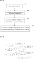
- FIG. 7 is a flowchart for transmitting a PT-RS for STxMP according to the disclosure.
- a UE receives information about a maximum number of PT-RSs being 2 from a BS, and then performs STxMP.
- a plurality of panels may correspond to a plurality of SRS resource sets configured for CB/NCB purposes or correspond to SRS resources indicated by a plurality of SRI fields.
- panel 1 and panel 2 may correspond to SRS resource set 0 and SRS resource set 1, respectively.
- panel 1 and panel 2 may correspond to SRS resources indicated by a first SRI field and SRS resources indicated by a second SRI field, or the plurality of panels may correspond to PMIs indicated by a plurality of TPMI fields.
- panel 1 may correspond to a PMI indicated by a first TPMI field
- panel 2 may correspond to a PMI indicated by a second TPMI field.
- a panel may be defined as a group of antenna ports having coherency.
- PUSCH antenna ports 1000 and 1002 may be defined as panel 1
- PUSCH antenna ports 1001 and 1003) may be defined as panel 2.
- PUSCH antenna ports 1000, 1002, 1004, and 1006 may be defined as panel 1
- PUSCH antenna ports 1001, 1003, 1005, and 1007 may be defined as panel 2.
- a PT-RS port index may be configured for each SRS resource, and SRS resources with the same PT-RS port index may be assumed to be transmitted in the same panel.
- the above proposal assumes two STxMP panels, two UL TCI states, and two spatial relation infos/RSs and PC sets configured for UL M-TRP transmission, this may be extended to N1, N2, and N3 STxMP panels, UL TCI states, spatial relation infos/RSs, and PC sets.
- the factors used in the proposals may be indicated to the UE by DCI/MAC-CE/RRC signaling from the BS, or the UE may report them to the BS.
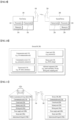
- a communication system 1 applied to the embodiment includes wireless devices, Base Stations (BSs), and a network.
- the wireless devices represent devices performing communication using Radio Access Technology (RAT) (e.g., 5G New RAT (NR)) or Long-Term Evolution (LTE)) and may be referred to as communication/radio/5G devices.
- RAT Radio Access Technology
- the wireless devices may include, without being limited to, a robot 100a, vehicles 100b-1 and 100b-2, an eXtended Reality (XR) device 100c, a hand-held device 100d, a home appliance 100e, an Internet of Things (IoT) device 100f, and an Artificial Intelligence (AI) device/server 400.
- RAT Radio Access Technology
- NR 5G New RAT
- LTE Long-Term Evolution
- the wireless devices may include, without being limited to, a robot 100a, vehicles 100b-1 and 100b-2, an eXtended Reality (XR) device 100c, a hand-held device 100d, a home appliance 100e
- the hand-held device may include a smartphone, a smartpad, a wearable device (e.g., a smartwatch or a smartglasses), and a computer (e.g., a notebook).
- the home appliance may include a TV, a refrigerator, and a washing machine.
- the IoT device may include a sensor and a smartmeter.
- the BSs and the network may be implemented as wireless devices and a specific wireless device 200a may operate as a BS/network node with respect to other wireless devices.
- the wireless devices 100a to 100f may be connected to the network 300 via the BSs 200.
- An AI technology may be applied to the wireless devices 100a to 100f and the wireless devices 100a to 100f may be connected to the AI server 400 via the network 300.
- the network 300 may be configured using a 3G network, a 4G (e.g., LTE) network, or a 5G (e.g., NR) network.
- the wireless devices 100a to 100f may communicate with each other through the BSs 200/network 300, the wireless devices 100a to 100f may perform direct communication (e.g., sidelink communication) with each other without passing through the BSs/network.
- the vehicles 100b-1 and 100b-2 may perform direct communication (e.g.
- Wireless communication/connections 150a, 150b, or 150c may be established between the wireless devices 100a to 100f/BS 200, or BS 200/BS 200.
- the wireless communication/connections may be established through various RATs (e.g., 5G NR) such as uplink/downlink communication 150a, sidelink communication 150b (or, D2D communication), or inter BS communication (e.g. relay, Integrated Access Backhaul(IAB)).
- the wireless devices and the BSs/the wireless devices may transmit/receive radio signals to/from each other through the wireless communication/connections 150a and 150b.
- the wireless communication/connections 150a and 150b may transmit/receive signals through various physical channels.
- various configuration information configuring processes various signal processing processes (e.g., channel encoding/decoding, modulation/demodulation, and resource mapping/demapping), and resource allocating processes, for transmitting/receiving radio signals, may be performed based on the various proposals of the embodiment.
- various signal processing processes e.g., channel encoding/decoding, modulation/demodulation, and resource mapping/demapping
- resource allocating processes for transmitting/receiving radio signals
- a first wireless device 100 and a second wireless device 200 may transmit radio signals through a variety of RATs (e.g., LTE and NR).
- ⁇ the first wireless device 100 and the second wireless device 200 ⁇ may correspond to ⁇ the wireless device 100x and the BS 200 ⁇ and/or ⁇ the wireless device 100x and the wireless device 100x ⁇ of FIG. 8 .
- the processor(s) 102 may receive radio signals including second information/signals through the transceiver 106 and then store information obtained by processing the second information/signals in the memory(s) 104.
- the memory(s) 104 may be connected to the processor(s) 102 and may store a variety of information related to operations of the processor(s) 102.
- the memory(s) 104 may store software code including commands for performing a part or the entirety of processes controlled by the processor(s) 102 or for performing the descriptions, functions, procedures, proposals, methods, and/or operational flowcharts disclosed in this document.
- the processor(s) 102 and the memory(s) 104 may be a part of a communication modem/circuit/chip designed to implement RAT (e.g., LTE or NR).
- the transceiver(s) 106 may be connected to the processor(s) 102 and transmit and/or receive radio signals through one or more antennas 108.
- Each of the transceiver(s) 106 may include a transmitter and/or a receiver.
- the transceiver(s) 106 may be interchangeably used with Radio Frequency (RF) unit(s).
- the wireless device may represent a communication modem/circuit/chip.
- the second wireless device 200 may include one or more processors 202 and one or more memories 204 and additionally further include one or more transceivers 206 and/or one or more antennas 208.
- the processor(s) 202 may control the memory(s) 204 and/or the transceiver(s) 206 and may be configured to implement the descriptions, functions, procedures, proposals, methods, and/or operational flowcharts disclosed in this document.
- the processor(s) 202 may process information within the memory(s) 204 to generate third information/signals and then transmit radio signals including the third information/signals through the transceiver(s) 206.
- One or more protocol layers may be implemented by, without being limited to, one or more processors 102 and 202.
- the one or more processors 102 and 202 may implement one or more layers (e.g., functional layers such as PHY, MAC, RLC, PDCP, RRC, and SDAP).
- the one or more processors 102 and 202 may generate one or more Protocol Data Units (PDUs) and/or one or more Service Data Unit (SDUs) according to the descriptions, functions, procedures, proposals, methods, and/or operational flowcharts disclosed in this document.
- PDUs Protocol Data Units
- SDUs Service Data Unit
- the one or more processors 102 and 202 may generate messages, control information, data, or information according to the descriptions, functions, procedures, proposals, methods, and/or operational flowcharts disclosed in this document.
- the one or more processors 102 and 202 may generate signals (e.g., baseband signals) including PDUs, SDUs, messages, control information, data, or information according to the descriptions, functions, procedures, proposals, methods, and/or operational flowcharts disclosed in this document and provide the generated signals to the one or more transceivers 106 and 206.
- the one or more processors 102 and 202 may receive the signals (e.g., baseband signals) from the one or more transceivers 106 and 206 and acquire the PDUs, SDUs, messages, control information, data, or information according to the descriptions, functions, procedures, proposals, methods, and/or operational flowcharts disclosed in this document.
- signals e.g., baseband signals
- the one or more processors 102 and 202 may be referred to as controllers, microcontrollers, microprocessors, or microcomputers.
- the one or more processors 102 and 202 may be implemented by hardware, firmware, software, or a combination thereof.
- ASICs Application Specific Integrated Circuits
- DSPs Digital Signal Processors
- DSPDs Digital Signal Processing Devices
- PLDs Programmable Logic Devices
- FPGAs Field Programmable Gate Arrays
- the descriptions, functions, procedures, proposals, methods, and/or operational flowcharts disclosed in this document may be implemented using firmware or software and the firmware or software may be configured to include the modules, procedures, or functions.
- Firmware or software configured to perform the descriptions, functions, procedures, proposals, methods, and/or operational flowcharts disclosed in this document may be included in the one or more processors 102 and 202 or stored in the one or more memories 104 and 204 so as to be driven by the one or more processors 102 and 202.
- the descriptions, functions, procedures, proposals, methods, and/or operational flowcharts disclosed in this document may be implemented using firmware or software in the form of code, commands, and/or a set of commands.
- the one or more memories 104 and 204 may be connected to the one or more processors 102 and 202 and store various types of data, signals, messages, information, programs, code, instructions, and/or commands.
- the one or more memories 104 and 204 may be configured by Read-Only Memories (ROMs), Random Access Memories (RAMs), Electrically Erasable Programmable Read-Only Memories (EPROMs), flash memories, hard drives, registers, cash memories, computer-readable storage media, and/or combinations thereof.
- the one or more memories 104 and 204 may be located at the interior and/or exterior of the one or more processors 102 and 202.
- the one or more memories 104 and 204 may be connected to the one or more processors 102 and 202 through various technologies such as wired or wireless connection.
- the one or more transceivers 106 and 206 may transmit user data, control information, and/or radio signals/channels, mentioned in the methods and/or operational flowcharts of this document, to one or more other devices.
- the one or more transceivers 106 and 206 may receive user data, control information, and/or radio signals/channels, mentioned in the descriptions, functions, procedures, proposals, methods, and/or operational flowcharts disclosed in this document, from one or more other devices.
- the one or more transceivers 106 and 206 may be connected to the one or more processors 102 and 202 and transmit and receive radio signals.
- the one or more processors 102 and 202 may perform control so that the one or more transceivers 106 and 206 may transmit user data, control information, or radio signals to one or more other devices.
- the one or more processors 102 and 202 may perform control so that the one or more transceivers 106 and 206 may receive user data, control information, or radio signals from one or more other devices.
- the one or more transceivers 106 and 206 may be connected to the one or more antennas 108 and 208 and the one or more transceivers 106 and 206 may be configured to transmit and receive user data, control information, and/or radio signals/channels, mentioned in the descriptions, functions, procedures, proposals, methods, and/or operational flowcharts disclosed in this document, through the one or more antennas 108 and 208.
- the one or more antennas may be a plurality of physical antennas or a plurality of logical antennas (e.g., antenna ports).
- the one or more transceivers 106 and 206 may convert received radio signals/channels etc.
- the one or more transceivers 106 and 206 may convert the user data, control information, radio signals/channels, etc. processed using the one or more processors 102 and 202 from the base band signals into the RF band signals.
- the one or more transceivers 106 and 206 may include (analog) oscillators and/or filters.
- FIG. 10 illustrates other exemplary wireless devices to which the embodiment is applied.
- the wireless devices may be implemented in various forms according to a use case/service (see FIG. 8 ).
- wireless devices 100 and 200 may correspond to the wireless devices 100 and 200 of FIG. 9 and may be configured by various elements, components, units/portions, and/or modules.
- each of the wireless devices 100 and 200 may include a communication unit 110, a control unit 120, a memory unit 130, and additional components 140.
- the communication unit may include a communication circuit 112 and transceiver(s) 114.
- the communication circuit 112 may include the one or more processors 102 and 202 and/or the one or more memories 104 and 204 of FIG. 9 .
- the transceiver(s) 114 may include the one or more transceivers 106 and 206 and/or the one or more antennas 108 and 208 of FIG. 9 .
- the control unit 120 is electrically connected to the communication unit 110, the memory 130, and the additional components 140 and controls overall operation of the wireless devices. For example, the control unit 120 may control an electric/mechanical operation of the wireless device based on programs/code/commands/information stored in the memory unit 130.
- the control unit 120 may transmit the information stored in the memory unit 130 to the exterior (e.g., other communication devices) via the communication unit 110 through a wireless/wired interface or store, in the memory unit 130, information received through the wireless/wired interface from the exterior (e.g., other communication devices) via the communication unit 110.
- the additional components 140 may be variously configured according to types of wireless devices.
- the additional components 140 may include at least one of a power unit/battery, input/output (I/O) unit, a driving unit, and a computing unit.
- the wireless device may be implemented in the form of, without being limited to, the robot (100a of FIG. 8 ), the vehicles (100b-1 and 100b-2 of FIG. 8 ), the XR device (100c of FIG. 8 ), the hand-held device (100d of FIG. 8 ), the home appliance (100e of FIG. 8 ), the IoT device (100f of FIG.
- the wireless device may be used in a mobile or fixed place according to a use-example/service.
- the entirety of the various elements, components, units/portions, and/or modules in the wireless devices 100 and 200 may be connected to each other through a wired interface or at least a part thereof may be wirelessly connected through the communication unit 110.
- the control unit 120 and the communication unit 110 may be connected by wire and the control unit 120 and first units (e.g., 130 and 140) may be wirelessly connected through the communication unit 110.
- Each element, component, unit/portion, and/or module within the wireless devices 100 and 200 may further include one or more elements.
- the control unit 120 may be configured by a set of one or more processors.
- control unit 120 may be configured by a set of a communication control processor, an application processor, an Electronic Control Unit (ECU), a graphical processing unit, and a memory control processor.
- memory 130 may be configured by a Random Access Memory (RAM), a Dynamic RAM (DRAM), a Read Only Memory (ROM)), a flash memory, a volatile memory, a non-volatile memory, and/or a combination thereof.
- RAM Random Access Memory
- DRAM Dynamic RAM
- ROM Read Only Memory
- flash memory a volatile memory
- non-volatile memory and/or a combination thereof.
- FIG. 11 illustrates an exemplary vehicle or autonomous driving vehicle to which the embodiment.
- the vehicle or autonomous driving vehicle may be implemented as a mobile robot, a car, a train, a manned/unmanned aerial vehicle (AV), a ship, or the like.
- AV manned/unmanned aerial vehicle
- the one or more memories 104 and 204 may be connected to the one or more processors 102 and 202 and store various types of data, signals, messages, information, programs, code, instructions, and/or commands.
- the one or more memories 104 and 204 may be configured by Read-Only Memories (ROMs), Random Access Memories (RAMs), Electrically Erasable Programmable Read-Only Memories (EPROMs), flash memories, hard drives, registers, cash memories, computer-readable storage media, and/or combinations thereof.
- the one or more memories 104 and 204 may be located at the interior and/or exterior of the one or more processors 102 and 202.
- the one or more memories 104 and 204 may be connected to the one or more processors 102 and 202 through various technologies such as wired or wireless connection.
- the one or more transceivers 106 and 206 may transmit user data, control information, and/or radio signals/channels, mentioned in the methods and/or operational flowcharts of this document, to one or more other devices.
- the one or more transceivers 106 and 206 may receive user data, control information, and/or radio signals/channels, mentioned in the descriptions, functions, procedures, proposals, methods, and/or operational flowcharts disclosed in this document, from one or more other devices.
- the one or more transceivers 106 and 206 may be connected to the one or more processors 102 and 202 and transmit and receive radio signals.
- the one or more processors 102 and 202 may perform control so that the one or more transceivers 106 and 206 may transmit user data, control information, or radio signals to one or more other devices.
- the one or more processors 102 and 202 may perform control so that the one or more transceivers 106 and 206 may receive user data, control information, or radio signals from one or more other devices.
- the one or more transceivers 106 and 206 may be connected to the one or more antennas 108 and 208 and the one or more transceivers 106 and 206 may be configured to transmit and receive user data, control information, and/or radio signals/channels, mentioned in the descriptions, functions, procedures, proposals, methods, and/or operational flowcharts disclosed in this document, through the one or more antennas 108 and 208.
- the one or more antennas may be a plurality of physical antennas or a plurality of logical antennas (e.g., antenna ports).
- the one or more transceivers 106 and 206 may convert received radio signals/channels etc.
- the one or more transceivers 106 and 206 may convert the user data, control information, radio signals/channels, etc. processed using the one or more processors 102 and 202 from the base band signals into the RF band signals.
- the one or more transceivers 106 and 206 may include (analog) oscillators and/or filters.
- FIG. 10 illustrates other exemplary wireless devices to which the embodiment is applied.
- the wireless devices may be implemented in various forms according to a use case/service (see FIG. 8 ).
- wireless devices 100 and 200 may correspond to the wireless devices 100 and 200 of FIG. 9 and may be configured by various elements, components, units/portions, and/or modules.
- each of the wireless devices 100 and 200 may include a communication unit 110, a control unit 120, a memory unit 130, and additional components 140.
- the communication unit may include a communication circuit 112 and transceiver(s) 114.
- the communication circuit 112 may include the one or more processors 102 and 202 and/or the one or more memories 104 and 204 of FIG. 14.
- the transceiver(s) 114 may include the one or more transceivers 106 and 206 and/or the one or more antennas 108 and 208 of FIG. 14.
- the control unit 120 is electrically connected to the communication unit 110, the memory 130, and the additional components 140 and controls overall operation of the wireless devices. For example, the control unit 120 may control an electric/mechanical operation of the wireless device based on programs/code/commands/information stored in the memory unit 130.
- the control unit 120 may transmit the information stored in the memory unit 130 to the exterior (e.g., other communication devices) via the communication unit 110 through a wireless/wired interface or store, in the memory unit 130, information received through the wireless/wired interface from the exterior (e.g., other communication devices) via the communication unit 110.
- the additional components 140 may be variously configured according to types of wireless devices.
- the additional components 140 may include at least one of a power unit/battery, input/output (I/O) unit, a driving unit, and a computing unit.
- the wireless device may be implemented in the form of, without being limited to, the robot (100a of FIG. 8 ), the vehicles (100b-1 and 100b-2 of FIG. 8 ), the XR device (100c of FIG. 13), the hand-held device (100d of FIG. 8 ), the home appliance (100e of FIG. 8 ), the IoT device (100f of FIG.
- the wireless device may be used in a mobile or fixed place according to a use-example/service.
- the entirety of the various elements, components, units/portions, and/or modules in the wireless devices 100 and 200 may be connected to each other through a wired interface or at least a part thereof may be wirelessly connected through the communication unit 110.
- the control unit 120 and the communication unit 110 may be connected by wire and the control unit 120 and first units (e.g., 130 and 140) may be wirelessly connected through the communication unit 110.
- Each element, component, unit/portion, and/or module within the wireless devices 100 and 200 may further include one or more elements.
- the control unit 120 may be configured by a set of one or more processors.
- control unit 120 may be configured by a set of a communication control processor, an application processor, an Electronic Control Unit (ECU), a graphical processing unit, and a memory control processor.
- memory 130 may be configured by a Random Access Memory (RAM), a Dynamic RAM (DRAM), a Read Only Memory (ROM)), a flash memory, a volatile memory, a non-volatile memory, and/or a combination thereof.
- RAM Random Access Memory
- DRAM Dynamic RAM
- ROM Read Only Memory
- flash memory a volatile memory
- non-volatile memory and/or a combination thereof.
- FIG. 11 illustrates an exemplary vehicle or autonomous driving vehicle to which the embodiment.
- the vehicle or autonomous driving vehicle may be implemented as a mobile robot, a car, a train, a manned/unmanned aerial vehicle (AV), a ship, or the like.
- AV manned/unmanned aerial vehicle
- a vehicle or autonomous driving vehicle 100 may include an antenna unit 108, a communication unit 110, a control unit 120, a driving unit 140a, a power supply unit 140b, a sensor unit 140c, and an autonomous driving unit 140d.
- the antenna unit 108 may be configured as a part of the communication unit 110.
- the blocks 110/130/140a to 140d correspond to the blocks 110/130/140 of FIG. 10 , respectively.
- the communication unit 110 may transmit and receive signals (e.g., data and control signals) to and from external devices such as other vehicles, BSs (e.g., gNBs and road side units), and servers.
- the control unit 120 may perform various operations by controlling elements of the vehicle or the autonomous driving vehicle 100.
- the control unit 120 may include an Electronic Control Unit (ECU).
- the driving unit 140a may cause the vehicle or the autonomous driving vehicle 100 to drive on a road.
- the driving unit 140a may include an engine, a motor, a powertrain, a wheel, a brake, a steering device, etc.
- the power supply unit 140b may supply power to the vehicle or the autonomous driving vehicle 100 and include a wired/wireless charging circuit, a battery, etc.
- the sensor unit 140c may acquire a vehicle state, ambient environment information, user information, etc.
- the sensor unit 140c may include an Inertial Measurement Unit (IMU) sensor, a collision sensor, a wheel sensor, a speed sensor, a slope sensor, a weight sensor, a heading sensor, a position module, a vehicle forward/backward sensor, a battery sensor, a fuel sensor, a tire sensor, a steering sensor, a temperature sensor, a humidity sensor, an ultrasonic sensor, an illumination sensor, a pedal position sensor, etc.
- IMU Inertial Measurement Unit
- the autonomous driving unit 140d may implement technology for maintaining a lane on which a vehicle is driving, technology for automatically adjusting speed, such as adaptive cruise control, technology for autonomously driving along a determined path, technology for driving by automatically setting a path if a destination is set, and the like.
- the communication unit 110 may receive map data, traffic information data, etc. from an external server.
- the autonomous driving unit 140d may generate an autonomous driving path and a driving plan from the obtained data.
- the control unit 120 may control the driving unit 140a such that the vehicle or the autonomous driving vehicle 100 may move along the autonomous driving path according to the driving plan (e.g., speed/direction control).
- the communication unit 110 may aperiodically/periodically acquire recent traffic information data from the external server and acquire surrounding traffic information data from neighboring vehicles.
- the sensor unit 140c may obtain a vehicle state and/or surrounding environment information.
- the autonomous driving unit 140d may update the autonomous driving path and the driving plan based on the newly obtained data/information.
- the communication unit 110 may transfer information about a vehicle position, the autonomous driving path, and/or the driving plan to the external server.
- the external server may predict traffic information data using AI technology, etc., based on the information collected from vehicles or autonomous driving vehicles and provide the predicted traffic information data to the vehicles or the autonomous driving vehicles.
- the disclosure is applicable to UEs, BSs, or other apparatuses in a wireless mobile communication system.
Landscapes
- Engineering & Computer Science (AREA)
- Signal Processing (AREA)
- Computer Networks & Wireless Communication (AREA)
- Databases & Information Systems (AREA)
- Mobile Radio Communication Systems (AREA)
Applications Claiming Priority (5)
| Application Number | Priority Date | Filing Date | Title |
|---|---|---|---|
| KR20220097239 | 2022-08-04 | ||
| KR20220121989 | 2022-09-26 | ||
| KR20230013727 | 2023-02-01 | ||
| KR20230021540 | 2023-02-17 | ||
| PCT/KR2023/010649 WO2024029808A1 (fr) | 2022-08-04 | 2023-07-24 | Procédé de transmission d'un signal de référence de suivi de phase pour une transmission simultanée à travers de multiples panneaux dans un système de communication sans fil, et appareil associé |
Publications (1)
| Publication Number | Publication Date |
|---|---|
| EP4568156A1 true EP4568156A1 (fr) | 2025-06-11 |
Family
ID=89849283
Family Applications (1)
| Application Number | Title | Priority Date | Filing Date |
|---|---|---|---|
| EP23850315.5A Pending EP4568156A1 (fr) | 2022-08-04 | 2023-07-24 | Procédé de transmission d'un signal de référence de suivi de phase pour une transmission simultanée à travers de multiples panneaux dans un système de communication sans fil, et appareil associé |
Country Status (6)
| Country | Link |
|---|---|
| US (1) | US20250317251A1 (fr) |
| EP (1) | EP4568156A1 (fr) |
| JP (1) | JP2025524877A (fr) |
| KR (1) | KR20250002143A (fr) |
| CN (1) | CN119301897A (fr) |
| WO (1) | WO2024029808A1 (fr) |
Cited By (1)
| Publication number | Priority date | Publication date | Assignee | Title |
|---|---|---|---|---|
| EP4415452A4 (fr) * | 2021-10-08 | 2025-10-29 | Lg Electronics Inc | Procédé et dispositif pour effectuer une transmission/réception en liaison montante dans un système de communication sans fil |
Families Citing this family (2)
| Publication number | Priority date | Publication date | Assignee | Title |
|---|---|---|---|---|
| US20240089151A1 (en) * | 2022-09-09 | 2024-03-14 | Qualcomm Incorporated | Phase tracking reference signal configuration for rate-splitting multiple input multiple output communications |
| WO2025208385A1 (fr) * | 2024-04-02 | 2025-10-09 | 北京小米移动软件有限公司 | Procédé de communication, terminal, dispositif de réseau, dispositif de communication et support de stockage |
Family Cites Families (6)
| Publication number | Priority date | Publication date | Assignee | Title |
|---|---|---|---|---|
| KR102380756B1 (ko) * | 2016-08-05 | 2022-03-31 | 삼성전자 주식회사 | 무선 통신 시스템에서 위상 보상 기준 신호를 송수신하는 방법 및 장치 |
| JP2019535208A (ja) * | 2016-11-09 | 2019-12-05 | エルジー エレクトロニクス インコーポレイティド | 無線通信システムにおける位相雑音除去のためのptrsのパワーブースティングレベルの決定方法及びその装置 |
| CN108259401B (zh) * | 2016-12-28 | 2020-09-15 | 电信科学技术研究院 | 参考信号发送方法和相位噪声确定方法及相关装置 |
| CN110537343B (zh) * | 2017-04-24 | 2022-05-06 | Lg电子株式会社 | 无线通信系统中由终端接收相位跟踪参考信号的方法及支持该方法的装置 |
| EP4229961A4 (fr) * | 2020-10-19 | 2024-09-18 | Apple Inc. | Transmission de signal de référence de suivi de phase pour l'amélioration de la fiabilité de canal partagé de liaison montante physique |
| KR20220103569A (ko) * | 2021-01-15 | 2022-07-22 | 삼성전자주식회사 | 네트워크 협력 통신 시스템을 위한 상향링크 위상 추적 기준 신호 송수신 방법 및 장치 |
-
2023
- 2023-07-24 JP JP2025503062A patent/JP2025524877A/ja active Pending
- 2023-07-24 KR KR1020247030188A patent/KR20250002143A/ko active Pending
- 2023-07-24 US US18/859,231 patent/US20250317251A1/en active Pending
- 2023-07-24 EP EP23850315.5A patent/EP4568156A1/fr active Pending
- 2023-07-24 WO PCT/KR2023/010649 patent/WO2024029808A1/fr not_active Ceased
- 2023-07-24 CN CN202380044343.5A patent/CN119301897A/zh active Pending
Cited By (1)
| Publication number | Priority date | Publication date | Assignee | Title |
|---|---|---|---|---|
| EP4415452A4 (fr) * | 2021-10-08 | 2025-10-29 | Lg Electronics Inc | Procédé et dispositif pour effectuer une transmission/réception en liaison montante dans un système de communication sans fil |
Also Published As
| Publication number | Publication date |
|---|---|
| KR20250002143A (ko) | 2025-01-07 |
| CN119301897A (zh) | 2025-01-10 |
| WO2024029808A1 (fr) | 2024-02-08 |
| US20250317251A1 (en) | 2025-10-09 |
| JP2025524877A (ja) | 2025-08-01 |
Similar Documents
| Publication | Publication Date | Title |
|---|---|---|
| US11831445B2 (en) | Method and device for transmitting and receiving signal in wireless communication system | |
| US20250254700A1 (en) | Method and apparatus for transmitting and receiving signal in wireless communication system | |
| US12324000B2 (en) | Method for transmitting or receiving signal in wireless communication system supporting unlicensed band, and apparatus supporting same | |
| EP4568156A1 (fr) | Procédé de transmission d'un signal de référence de suivi de phase pour une transmission simultanée à travers de multiples panneaux dans un système de communication sans fil, et appareil associé | |
| EP4564696A1 (fr) | Procédé de transmission d'informations d'état de canal pour une transmission à base de trp multiples dans un système de communication sans fil, et appareil associé | |
| US12096480B2 (en) | Method and apparatus for transmitting and receiving wireless signal in wireless communication system | |
| US12432036B2 (en) | Method and apparatus for transmitting/receiving wireless signal in wireless communication system | |
| US20250234355A1 (en) | Method and device for transmitting and receiving signal in wireless communication system | |
| US20240389111A1 (en) | Method and device for transmitting and receiving signal in wireless communication system | |
| US12068866B2 (en) | Method and apparatus for transmitting/receiving wireless signal in wireless communication system | |
| EP4597858A1 (fr) | Procédé et appareil de transmission et de réception de signal dans un système de communication sans fil | |
| EP4668981A1 (fr) | Procédé et dispositif de transmission et de réception de signaux dans un système de communication sans fil | |
| US12028855B2 (en) | Method and apparatus for transmitting/receiving wireless signal in wireless communication system | |
| US20230389066A1 (en) | Method and device for transmitting and receiving signal in wireless communication system | |
| EP4572211A1 (fr) | Procédé de fourniture d'informations de configuration de dm-rs dans un système de communication sans fil et dispositif associé | |
| EP4572431A1 (fr) | Procédé de commande de puissance de transmission pour une transmission simultanée à travers de multiples panneaux dans un système de communication sans fil et appareil associé | |
| US20250373288A1 (en) | Method and device for transmitting and receiving signal in wireless communication system | |
| EP4661515A1 (fr) | Procédé et dispositif de transmission/réception de signal dans un système de communication sans fil | |
| EP4618463A1 (fr) | Procédé et appareil d'émission et de réception de signaux dans un système de communication sans fil | |
| US20260075620A1 (en) | Method and device for transmitting and receiving wireless signal in wireless communication system | |
| EP4648305A2 (fr) | Procédé et dispositif d'émission/réception de signal dans un système de communication sans fil |
Legal Events
| Date | Code | Title | Description |
|---|---|---|---|
| STAA | Information on the status of an ep patent application or granted ep patent |
Free format text: STATUS: THE INTERNATIONAL PUBLICATION HAS BEEN MADE |
|
| PUAI | Public reference made under article 153(3) epc to a published international application that has entered the european phase |
Free format text: ORIGINAL CODE: 0009012 |
|
| STAA | Information on the status of an ep patent application or granted ep patent |
Free format text: STATUS: REQUEST FOR EXAMINATION WAS MADE |
|
| 17P | Request for examination filed |
Effective date: 20241219 |
|
| AK | Designated contracting states |
Kind code of ref document: A1 Designated state(s): AL AT BE BG CH CY CZ DE DK EE ES FI FR GB GR HR HU IE IS IT LI LT LU LV MC ME MK MT NL NO PL PT RO RS SE SI SK SM TR |
|
| DAV | Request for validation of the european patent (deleted) | ||
| DAX | Request for extension of the european patent (deleted) |