EP4568285A1 - Verfahren zum betrieb eines binauralen hörinstruments - Google Patents
Verfahren zum betrieb eines binauralen hörinstruments Download PDFInfo
- Publication number
- EP4568285A1 EP4568285A1 EP23214658.9A EP23214658A EP4568285A1 EP 4568285 A1 EP4568285 A1 EP 4568285A1 EP 23214658 A EP23214658 A EP 23214658A EP 4568285 A1 EP4568285 A1 EP 4568285A1
- Authority
- EP
- European Patent Office
- Prior art keywords
- signal
- directional
- generated
- signals
- input
- Prior art date
- Legal status (The legal status is an assumption and is not a legal conclusion. Google has not performed a legal analysis and makes no representation as to the accuracy of the status listed.)
- Pending
Links
Images


Classifications
-
- H—ELECTRICITY
- H04—ELECTRIC COMMUNICATION TECHNIQUE
- H04R—LOUDSPEAKERS, MICROPHONES, GRAMOPHONE PICK-UPS OR LIKE ACOUSTIC ELECTROMECHANICAL TRANSDUCERS; ELECTRIC HEARING AIDS; PUBLIC ADDRESS SYSTEMS
- H04R25/00—Electric hearing aids
- H04R25/55—Electric hearing aids using an external connection, either wireless or wired
- H04R25/552—Binaural
-
- H—ELECTRICITY
- H04—ELECTRIC COMMUNICATION TECHNIQUE
- H04R—LOUDSPEAKERS, MICROPHONES, GRAMOPHONE PICK-UPS OR LIKE ACOUSTIC ELECTROMECHANICAL TRANSDUCERS; ELECTRIC HEARING AIDS; PUBLIC ADDRESS SYSTEMS
- H04R25/00—Electric hearing aids
- H04R25/40—Arrangements for obtaining a desired directivity characteristic
- H04R25/407—Circuits for combining signals of a plurality of transducers
-
- H—ELECTRICITY
- H04—ELECTRIC COMMUNICATION TECHNIQUE
- H04R—LOUDSPEAKERS, MICROPHONES, GRAMOPHONE PICK-UPS OR LIKE ACOUSTIC ELECTROMECHANICAL TRANSDUCERS; ELECTRIC HEARING AIDS; PUBLIC ADDRESS SYSTEMS
- H04R25/00—Electric hearing aids
- H04R25/50—Customised settings for obtaining desired overall acoustical characteristics
-
- H—ELECTRICITY
- H04—ELECTRIC COMMUNICATION TECHNIQUE
- H04R—LOUDSPEAKERS, MICROPHONES, GRAMOPHONE PICK-UPS OR LIKE ACOUSTIC ELECTROMECHANICAL TRANSDUCERS; ELECTRIC HEARING AIDS; PUBLIC ADDRESS SYSTEMS
- H04R25/00—Electric hearing aids
- H04R25/50—Customised settings for obtaining desired overall acoustical characteristics
- H04R25/505—Customised settings for obtaining desired overall acoustical characteristics using digital signal processing
-
- H—ELECTRICITY
- H04—ELECTRIC COMMUNICATION TECHNIQUE
- H04R—LOUDSPEAKERS, MICROPHONES, GRAMOPHONE PICK-UPS OR LIKE ACOUSTIC ELECTROMECHANICAL TRANSDUCERS; ELECTRIC HEARING AIDS; PUBLIC ADDRESS SYSTEMS
- H04R2225/00—Details of deaf aids covered by H04R25/00, not provided for in any of its subgroups
- H04R2225/43—Signal processing in hearing aids to enhance the speech intelligibility
Definitions
- Hearing instruments in general, and hearing aids in particular, are usually designed to be worn on the head and here in particular in or on one ear of the user, especially as behind-the-ear (BTE) or in-the-ear (ITE) devices.
- hearing instruments regularly have at least one output transducer that converts an output audio signal supplied for the purpose of output into a signal that can be perceived by the user as sound, and outputs the latter to the user.
- the output transducer is designed as an electro-acoustic transducer that converts the (electrical) output audio signal into an airborne sound, whereby this output airborne sound is emitted into the user's ear canal.
- the output transducer also called the "receiver”
- the output transducer is usually integrated outside the ear in a housing of the hearing instrument.
- the sound emitted by the output transducer is guided into the user's ear canal by means of a sound tube.
- the output transducer can also be located in the ear canal, and thus outside the housing worn behind the ear.
- Such hearing instruments are also called RIC devices (Receiver In Channel).
- Hearing instruments worn in the ear, which are so small that they do not protrude outside the ear canal are also called CIC devices (Completely in Canal).
- the output transducer can also be designed as an electro-mechanical transducer that converts the output audio signal into structure-borne sound (vibrations), whereby this structure-borne sound is emitted into the skull bone of the user, for example.
- structure-borne sound vibrations
- a hearing instrument often has a signal processing unit (signal processor).
- the or each input signal is processed (i.e. modified with respect to its sound information).
- the signal processing unit thereby outputs an appropriately processed audio signal (also referred to as "output audio signal”, “output signal” or “modified sound signal”) to the output transducer and/or to an external device.
- ADM adaptive differential directional microphone
- a directional signal is generated in such a way that it has a maximum attenuation in the direction of an assumed, localisable noise source.
- the assumption used for this is usually that sounds occurring from the area behind the hearing instrument user, i.e. in his or her posterior hemisphere, are basically to be treated as background noise.
- conventional directional microphone algorithms usually minimise the signal energy from the posterior hemisphere to produce the directional signal with the desired attenuation characteristics.
- the directional signal or its directional characteristic has a spatial notch, i.e. an angle of minimum sensitivity. This angle (range) or notch has preferably a total ("infinite”) attenuation or attenuation, so that the sound of the localised noise source is ideally completely faded out of the directional signal.
- the input signals of the input transducers of a single hearing device are processed with an adaptive matching or adaptation parameter.
- an adaptive matching or adaptation parameter As a rule, a linear combination of the input signals (or signals derived from them) is carried out, whereby the adaptation parameter is used as a linear factor.
- the adaptation parameters of an adaptive differential directional microphone basically adjust independently on the left and right ear side.
- the adaptation parameters of the individual hearing devices usually differ because an adjustment of the adaptation parameters in the course of directional signal processing essentially aims at minimising the output signal, i.e. directing the notch towards a dominant noise source in the rear half-space.
- subcardioid is a directional characteristic between omni(-directional) and cardioid, i.e. between circular/spherical and heart-shaped.
- All directional patterns for subcardioids have their (more or less deep, depending on the adaptation parameter) notch at a directional angle of 180°.
- a mislocalisation of a noise source in the rear half-space may occur due to the different attenuation in 180° direction on both sides.
- different attenuation would be applied on the left and right sides for the corresponding directions of incidence, i.e. the attenuation for a source from +120° on the right side would differ from the attenuation for a source from -120°.
- the invention is based on the task of specifying a particularly suitable method for operating a binaural hearing instrument.
- an improved directional signal processing especially in listening situations without a dominant noise source, is to be specified.
- the invention is further based on the task of specifying a particularly suitable binaural hearing instrument for carrying out the method.
- the forward and backward signals are processed in the individual hearing devices to form a first directional signal, whereby the first directional signal or its directional effect is attenuated in at least one (spatial) direction or in an angular range.
- the first directional signal is therefore not an omnidirectional (spherical) signal but has a nontrivial directional characteristic.
- the forward and backward signals are processed by means of a linear combination, whereby an adaptation parameter (adjustment parameter) is determined as a linear factor. For example, for the first directional signal, the sum of the forward signal and a backward signal multiplied by the adaptation parameter is formed.
- the determined adaptation parameters are each compared with a stored threshold value, whereby the same threshold value is stored in both individual hearing devices.
- both adaptation parameters are compared with the same threshold value in each individual hearing device. If at least one of the adaptation parameters falls below the threshold value, the adaptation parameters of the individual hearing devices are synchronised with each other, i.e. tuned or aligned. For this purpose, corresponding information and data are exchanged via the signalling coupling of the individual hearing devices, so that the same synchronised adaptation parameter is available in both individual hearing devices after synchronisation.
- a second directional signal is generated in each of the individual hearing devices using the synchronised adaptation parameter.
- the forward and backward signals are linked or processed by means of the synchronised adaptation parameter.
- the individual hearing devices each generate an output signal based on the second directional signals, which is preferably converted into an output sound signal via a respective output converter of the individual hearing devices.
- the two individual hearing devices are worn by the user on different sides of the head so that each individual hearing device is assigned to one ear.
- the individual hearing devices are preferably designed as hearing aids, for example, which have at least two input transducers and at least one output transducer and are thus designed to pick up sound signals from the environment and output them to a user of the hearing instrument.
- each of the individual hearing devices has a wireless interface for signal or data exchange between the two individual hearing devices.
- the wireless interface is designed, for example, as a Bluetooth or induction transceiver.
- an input transducer means in particular an electro-acoustic transducer, such as a microphone, which is intended and set up to generate a corresponding electrical signal from a sound signal.
- the input signals are thus in particular electrical (audio) signals.
- signal preprocessing is also carried out, for example in the form of (linear) preamplification and/or analogue-to-digital conversion (A/D conversion).
- the first and second input converters of the individual hearing devices are designed in particular as directional microphones and are interconnected accordingly.
- the signal components of the first and the second input signal are preferably included in the forward or backward signal, respectively.
- the first and the second input signal are not both used simultaneously only for a generation of control parameters or the like which are applied to signal components of other signals.
- at least the signal components of the first input signal, and particularly preferably also the signal components of the second input signal enter linearly into the forward signal or into the backward signal. The same applies to the generation of the second directional signal on the basis of the forward signal and the backward signal, as well as possibly for other signals and their corresponding generation.
- the generation of a signal can also be carried out from the generating signals (e.g., the forward signal and the backward signal) in such a way that one or more intermediate signals are first formed from the said generating signals within the framework of the signal processing, from which the generated signal (e.g., the second directional signal) is then determined.
- the signal components of the generating signals i.e., in the present example the forward and backward signals, are then first incorporated into the respective intermediate signal, and the signal components of the respective intermediate signal are then incorporated into the generated signal, i.e. in the present case into the second directional signal, so that the signal components of the generating signals (i.e. e.g.
- the forward signal and the second directional signal are then determined.
- the signal components of the respective intermediate signal then enter the generated signal, i.e. in this case the second directional signal, so that the signal components of the generating signals (e.g. the forward signal and the backward signal) are "passed through” via the respective intermediate signal to the generated signal (i.e. e.g. the second directional signal) and, if necessary, are amplified (attenuated) frequency band by frequency band and/or are partially (time) delayed against each other and/or are weighted differently to each other, etc.
- a "directional signal” is understood here and in the following to mean in particular an electrical (audio) signal that is generated by selectively detecting sound waves from a certain direction.
- the directional signal thus has a certain directional characteristic or directionality. This means that the directional signal has an angular dependency, so that acoustic signals are detected or captured unevenly over the solid angle.
- the directional signal has a directional characteristic in the form of a heart or a kidney (cardioid) or a supercardioid .
- a "forward signal” is understood here and in the following to be in particular a directional signal with a non-trivial directional characteristic, which in a front half-space (front hemisphere) of the respective individual hearing device has on average a higher sensitivity to a standardised test sound of a predetermined level than in a rear half-space (rear hemisphere).
- the direction of maximum sensitivity of the forward signal also lies in the front hemisphere, in particular in the forward direction (i.e. at 0° with respect to a preferred direction of the individual hearing device), while a direction of minimum sensitivity of the forward signal lies in the rear hemisphere, in particular in the rearward direction (i.e. at 180° with respect to a forward direction of the individual hearing device).
- the forward and the backward signal are symmetrical to each other with respect to a symmetry plane perpendicular to said preferred direction.
- the directional characteristic of the forward signal is given by a cardioid
- the directional characteristic of the backward signal is given correspondingly by an anti-cardioid.
- the adaptation parameter (a) can be determined without the signal resulting from the linear combination, which corresponds to the first directional signal, being subject to further use in the course of the further procedure.
- the second directional signal is generated directly from the forward signal and the backward signal.
- the adaptation parameter is adjusted or set by said minimisation of the signal energy or by other methods of optimisation in such a way that the resulting first directional signal, even if it has no further use, has the attenuation in a direction as required.
- synchronising or a “synchronisation” of the adaptation parameters means in particular an adjustment or adaptation of the adaptation parameter setting between the individual hearing devices, so that the adaptation parameters after synchronisation, i.e. the synchronised adaptation parameters, have the same parameter value in the left and right individual hearing device.
- the output signal is in particular an electrical audio signal which is output by means of an output transducer, in particular an electro-acoustic output transducer, such as a loudspeaker, as an output sound signal from the individual hearing device to the user.
- an output transducer in particular an electro-acoustic output transducer, such as a loudspeaker, as an output sound signal from the individual hearing device to the user.
- the second directional signals are generated by a linear combination of the respective forward signals and backward signals with the synchronised adaptation parameter as a linear factor. For example, the sum of the forward signal and a backward signal multiplied by the synchronised adaptation parameter is formed for the second directional signal.
- the adaptation parameters of the individual hearing devices are synchronised with each other if both adaptation parameters fall below the threshold value.
- the adaptation parameter essentially determines the shape or form of the first directional signal, i.e. its directional characteristic
- the threshold value comparison essentially corresponds to a check whether a certain directional characteristic is present, i.e. whether a certain hearing or noise situation is present with the received input signals.
- the fact that synchronisation is only carried out if both adaptation parameters fall below the threshold value ensures that the adaptation parameters are only synchronised if essentially the same hearing or noise situation is present for both individual hearing devices, i.e. if the directional characteristics are already similar to each other.
- the threshold characterises a subcardioid range, i.e. a parameter range in which a subcardioid directional characteristic of the first directional signals is present.
- the synchronisation of the adaptation parameters on the left and right side offers for the subcardioid range both an optimal attenuation of in-terferers for the directional case (between 'eight' and cardioid directional characteristics) and at the same time an improved spatial perception and localisation for the subcardioid range (between cardioid and (omni) sphere) compared to non-synchronised adaptation parameters.
- the kind of mislocalisation mentioned at the beginning is avoided.
- all surrounding noise sources from the rear half-space would be attenuated symmetrically, so that the direction of arrival (DOA) dependent attenuation becomes symmetrical for the left and right single unit, which is advantageous for a natural spatial perception.
- DOA direction of arrival
- the adaptation parameters have a value range between -1 and 2.
- An adaptation parameter value of -1 corresponds to an omnidirectional (spherical) directional characteristic, where 0 corresponds to a cardioid or cardioid (notch at 180°) directional characteristic.
- a directivity parameter of 0.33 is a so-called supercardioid directivity (notch at 125°) and 0.5 is a hypercardioid directivity (notch at 109°).
- the resulting directional signal has an eight-shaped directional characteristic (notch at 90°) and with 2 a directional characteristic with notch at 70°.
- the value range between -1 and 0 is the subcardioid range. Accordingly, 0 is preferably used as the threshold value, so that a subcardioid directional characteristic is given or ensured if the value falls below the threshold value.
- a maximum or minimum value is used as the synchronisation mechanism.
- a maximum or minimum value of the adaptation parameters is used to synchronise the adaptation parameters.
- the maximum or minimum adaptation parameter is used as the synchronised adaptation parameter for both individual hearing devices.
- the maximum adaptation parameter is preferably used if an overall more residual directivity is desired than using the minimum adaptation parameter, since the directivity strength of effect (SoEff) is higher for higher adaptation parameters.
- the synchronisation mechanism is based on a weighting of the left and right adaptation parameters depending on the signal levels on both sides.
- the adaptation parameters are evaluated as a function of a respective signal level of the first directional signals.
- a signal level is determined for the first directional signals and the adaptation parameters are weighted for synchronisation based on this level.
- the adaptation parameter of the respective hearing device is denoted as a_local, while a_remote refers to the adaptation parameter of the other hearing device, and a_final is the synchronized value.
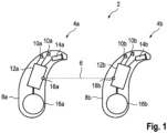
- the method is in particular a directional signal processing of the binaural hearing instrument 2, which is essentially implemented in a controller of the respective signal processing units 12a, 12b.
- the method is explained below for the signal processing of the individual hearing device 4a as an example. In the individual hearing device 4b, the procedure is carried out accordingly.
Landscapes
- Engineering & Computer Science (AREA)
- Health & Medical Sciences (AREA)
- General Health & Medical Sciences (AREA)
- Neurosurgery (AREA)
- Otolaryngology (AREA)
- Physics & Mathematics (AREA)
- Acoustics & Sound (AREA)
- Signal Processing (AREA)
- Computer Networks & Wireless Communication (AREA)
- Circuit For Audible Band Transducer (AREA)
Priority Applications (3)
| Application Number | Priority Date | Filing Date | Title |
|---|---|---|---|
| EP23214658.9A EP4568285A1 (de) | 2023-12-06 | 2023-12-06 | Verfahren zum betrieb eines binauralen hörinstruments |
| CN202411181899.1A CN120111423A (zh) | 2023-12-06 | 2024-08-27 | 运行双耳听力器械的方法 |
| US18/956,925 US20250193610A1 (en) | 2023-12-06 | 2024-11-22 | Method of operating a binaural hearing instrument and binaural hearing instrument |
Applications Claiming Priority (1)
| Application Number | Priority Date | Filing Date | Title |
|---|---|---|---|
| EP23214658.9A EP4568285A1 (de) | 2023-12-06 | 2023-12-06 | Verfahren zum betrieb eines binauralen hörinstruments |
Publications (1)
| Publication Number | Publication Date |
|---|---|
| EP4568285A1 true EP4568285A1 (de) | 2025-06-11 |
Family
ID=89121849
Family Applications (1)
| Application Number | Title | Priority Date | Filing Date |
|---|---|---|---|
| EP23214658.9A Pending EP4568285A1 (de) | 2023-12-06 | 2023-12-06 | Verfahren zum betrieb eines binauralen hörinstruments |
Country Status (3)
| Country | Link |
|---|---|
| US (1) | US20250193610A1 (de) |
| EP (1) | EP4568285A1 (de) |
| CN (1) | CN120111423A (de) |
Citations (3)
| Publication number | Priority date | Publication date | Assignee | Title |
|---|---|---|---|---|
| EP1773100A1 (de) | 2005-10-04 | 2007-04-11 | Siemens Audiologische Technik GmbH | Anpassung eines Richtmikrofons an langandauernde Einflüsse |
| US20170347206A1 (en) * | 2016-05-30 | 2017-11-30 | Oticon A/S | Hearing aid comprising a beam former filtering unit comprising a smoothing unit |
| US20190394586A1 (en) * | 2018-06-22 | 2019-12-26 | Oticon A/S | Hearing device comprising an acoustic event detector |
Family Cites Families (11)
| Publication number | Priority date | Publication date | Assignee | Title |
|---|---|---|---|---|
| US6549633B1 (en) * | 1998-02-18 | 2003-04-15 | Widex A/S | Binaural digital hearing aid system |
| WO2007106399A2 (en) * | 2006-03-10 | 2007-09-20 | Mh Acoustics, Llc | Noise-reducing directional microphone array |
| US20040175008A1 (en) * | 2003-03-07 | 2004-09-09 | Hans-Ueli Roeck | Method for producing control signals, method of controlling signal and a hearing device |
| CN102771144B (zh) * | 2010-02-19 | 2015-03-25 | 西门子医疗器械公司 | 用于方向相关空间噪声减低的设备和方法 |
| DE102013207149A1 (de) * | 2013-04-19 | 2014-11-06 | Siemens Medical Instruments Pte. Ltd. | Steuerung der Effektstärke eines binauralen direktionalen Mikrofons |
| US10536785B2 (en) * | 2017-12-05 | 2020-01-14 | Gn Hearing A/S | Hearing device and method with intelligent steering |
| US10728677B2 (en) * | 2017-12-13 | 2020-07-28 | Oticon A/S | Hearing device and a binaural hearing system comprising a binaural noise reduction system |
| US10425745B1 (en) * | 2018-05-17 | 2019-09-24 | Starkey Laboratories, Inc. | Adaptive binaural beamforming with preservation of spatial cues in hearing assistance devices |
| EP3606100B1 (de) * | 2018-07-31 | 2021-02-17 | Starkey Laboratories, Inc. | Automatische steuerung binauraler merkmale von im ohr tragbaren vorrichtungen |
| EP3629602B1 (de) * | 2018-09-27 | 2025-05-21 | Oticon A/s | Hörvorrichtung und ein hörsystem mit einer vielzahl von adaptiven zweikanaligen beamformern |
| WO2021110924A1 (en) * | 2019-12-04 | 2021-06-10 | Widex A/S | A hearing aid and a method of operating a hearing aid |
-
2023
- 2023-12-06 EP EP23214658.9A patent/EP4568285A1/de active Pending
-
2024
- 2024-08-27 CN CN202411181899.1A patent/CN120111423A/zh active Pending
- 2024-11-22 US US18/956,925 patent/US20250193610A1/en active Pending
Patent Citations (3)
| Publication number | Priority date | Publication date | Assignee | Title |
|---|---|---|---|---|
| EP1773100A1 (de) | 2005-10-04 | 2007-04-11 | Siemens Audiologische Technik GmbH | Anpassung eines Richtmikrofons an langandauernde Einflüsse |
| US20170347206A1 (en) * | 2016-05-30 | 2017-11-30 | Oticon A/S | Hearing aid comprising a beam former filtering unit comprising a smoothing unit |
| US20190394586A1 (en) * | 2018-06-22 | 2019-12-26 | Oticon A/S | Hearing device comprising an acoustic event detector |
Also Published As
| Publication number | Publication date |
|---|---|
| CN120111423A (zh) | 2025-06-06 |
| US20250193610A1 (en) | 2025-06-12 |
Similar Documents
| Publication | Publication Date | Title |
|---|---|---|
| US10431239B2 (en) | Hearing system | |
| US11510017B2 (en) | Hearing device comprising a microphone adapted to be located at or in the ear canal of a user | |
| EP3101919B1 (de) | Peer-to-peer-hörsystem | |
| EP3588985B1 (de) | Binaurales hörvorrichtungssystem mit binauraler aktiver okklusionsunterdrückung | |
| EP3883266A1 (de) | Zur bereitstellung einer schätzung der eigenen stimme eines benutzers angepasstes hörgerät | |
| EP3051844B1 (de) | Binaurales Hörsystem | |
| US10070231B2 (en) | Hearing device with input transducer and wireless receiver | |
| CN109845296B (zh) | 双耳助听器系统和操作双耳助听器系统的方法 | |
| CN107708045B (zh) | 用于改善听力系统中的接收信号的方法 | |
| US20150036850A1 (en) | Method for following a sound source, and hearing aid device | |
| JP2022528579A (ja) | 時間的非相関化ビームフォーマを備えるバイラテラル補聴器システム | |
| US9565499B2 (en) | Binaural hearing aid system for compensation of microphone deviations based on the wearer's own voice | |
| US20060233409A1 (en) | Hearing aid | |
| CN115811691B (zh) | 用于运行听力设备的方法和听力设备 | |
| US8218800B2 (en) | Method for setting a hearing system with a perceptive model for binaural hearing and corresponding hearing system | |
| US20250193610A1 (en) | Method of operating a binaural hearing instrument and binaural hearing instrument | |
| US9570089B2 (en) | Hearing system and transmission method | |
| CN118368572A (zh) | 用于运行听力设备的方法 |
Legal Events
| Date | Code | Title | Description |
|---|---|---|---|
| PUAI | Public reference made under article 153(3) epc to a published international application that has entered the european phase |
Free format text: ORIGINAL CODE: 0009012 |
|
| STAA | Information on the status of an ep patent application or granted ep patent |
Free format text: STATUS: THE APPLICATION HAS BEEN PUBLISHED |
|
| AK | Designated contracting states |
Kind code of ref document: A1 Designated state(s): AL AT BE BG CH CY CZ DE DK EE ES FI FR GB GR HR HU IE IS IT LI LT LU LV MC ME MK MT NL NO PL PT RO RS SE SI SK SM TR |
|
| STAA | Information on the status of an ep patent application or granted ep patent |
Free format text: STATUS: REQUEST FOR EXAMINATION WAS MADE |
|
| 17P | Request for examination filed |
Effective date: 20250717 |