EP4568360A1 - Procédé, équipement utilisateur, dispositif de traitement, support de stockage, et programme informatique de réception de canal de liaison descendante, et procédé et station de base de transmission de canal de liaison descendante - Google Patents
Procédé, équipement utilisateur, dispositif de traitement, support de stockage, et programme informatique de réception de canal de liaison descendante, et procédé et station de base de transmission de canal de liaison descendante Download PDFInfo
- Publication number
- EP4568360A1 EP4568360A1 EP23850411.2A EP23850411A EP4568360A1 EP 4568360 A1 EP4568360 A1 EP 4568360A1 EP 23850411 A EP23850411 A EP 23850411A EP 4568360 A1 EP4568360 A1 EP 4568360A1
- Authority
- EP
- European Patent Office
- Prior art keywords
- drx
- cell
- specific
- duration
- active time
- Prior art date
- Legal status (The legal status is an assumption and is not a legal conclusion. Google has not performed a legal analysis and makes no representation as to the accuracy of the status listed.)
- Pending
Links
Images



Classifications
-
- H—ELECTRICITY
- H04—ELECTRIC COMMUNICATION TECHNIQUE
- H04W—WIRELESS COMMUNICATION NETWORKS
- H04W76/00—Connection management
- H04W76/20—Manipulation of established connections
- H04W76/28—Discontinuous transmission [DTX]; Discontinuous reception [DRX]
-
- H—ELECTRICITY
- H04—ELECTRIC COMMUNICATION TECHNIQUE
- H04W—WIRELESS COMMUNICATION NETWORKS
- H04W52/00—Power management, e.g. Transmission Power Control [TPC] or power classes
- H04W52/02—Power saving arrangements
-
- H—ELECTRICITY
- H04—ELECTRIC COMMUNICATION TECHNIQUE
- H04W—WIRELESS COMMUNICATION NETWORKS
- H04W52/00—Power management, e.g. Transmission Power Control [TPC] or power classes
- H04W52/02—Power saving arrangements
- H04W52/0203—Power saving arrangements in the radio access network or backbone network of wireless communication networks
- H04W52/0206—Power saving arrangements in the radio access network or backbone network of wireless communication networks in access points, e.g. base stations
-
- H—ELECTRICITY
- H04—ELECTRIC COMMUNICATION TECHNIQUE
- H04W—WIRELESS COMMUNICATION NETWORKS
- H04W52/00—Power management, e.g. Transmission Power Control [TPC] or power classes
- H04W52/02—Power saving arrangements
- H04W52/0209—Power saving arrangements in terminal devices
- H04W52/0212—Power saving arrangements in terminal devices managed by the network, e.g. network or access point is leader and terminal is follower
- H04W52/0216—Power saving arrangements in terminal devices managed by the network, e.g. network or access point is leader and terminal is follower using a pre-established activity schedule, e.g. traffic indication frame
-
- H—ELECTRICITY
- H04—ELECTRIC COMMUNICATION TECHNIQUE
- H04W—WIRELESS COMMUNICATION NETWORKS
- H04W72/00—Local resource management
- H04W72/20—Control channels or signalling for resource management
- H04W72/23—Control channels or signalling for resource management in the downlink direction of a wireless link, i.e. towards a terminal
-
- H—ELECTRICITY
- H04—ELECTRIC COMMUNICATION TECHNIQUE
- H04W—WIRELESS COMMUNICATION NETWORKS
- H04W74/00—Wireless channel access
- H04W74/002—Transmission of channel access control information
-
- H—ELECTRICITY
- H04—ELECTRIC COMMUNICATION TECHNIQUE
- H04W—WIRELESS COMMUNICATION NETWORKS
- H04W74/00—Wireless channel access
- H04W74/08—Non-scheduled access, e.g. ALOHA
- H04W74/0833—Random access procedures, e.g. with 4-step access
-
- Y—GENERAL TAGGING OF NEW TECHNOLOGICAL DEVELOPMENTS; GENERAL TAGGING OF CROSS-SECTIONAL TECHNOLOGIES SPANNING OVER SEVERAL SECTIONS OF THE IPC; TECHNICAL SUBJECTS COVERED BY FORMER USPC CROSS-REFERENCE ART COLLECTIONS [XRACs] AND DIGESTS
- Y02—TECHNOLOGIES OR APPLICATIONS FOR MITIGATION OR ADAPTATION AGAINST CLIMATE CHANGE
- Y02D—CLIMATE CHANGE MITIGATION TECHNOLOGIES IN INFORMATION AND COMMUNICATION TECHNOLOGIES [ICT], I.E. INFORMATION AND COMMUNICATION TECHNOLOGIES AIMING AT THE REDUCTION OF THEIR OWN ENERGY USE
- Y02D30/00—Reducing energy consumption in communication networks
- Y02D30/70—Reducing energy consumption in communication networks in wireless communication networks
Definitions
- the present disclosure relates to a wireless communication system.
- M2M machine-to-machine
- MTC machine type communication
- PCs personal computers
- MIMO multiple input multiple output
- BS multi-base station
- eMBB enhanced mobile broadband
- RAT legacy radio access technology
- massive machine type communication for providing various services at anytime and anywhere by connecting a plurality of devices and objects to each other is one main issue to be considered in next-generation communication.
- the present disclosure is to provide energy saving methods and/or procedures for a base station (BS) and a user equipment (UE).
- BS base station
- UE user equipment
- the present disclosure provides methods and/or procedures for dynamically indicating an offset value relative to a discontinuous reception (DRX) cycle starting point.
- DRX discontinuous reception
- the present disclosure also provides methods and/or procedures for configuring/indicating ON/OFF for an ON duration of a DRX cycle.
- the present disclosure also provides methods and/or procedures for configuring a DRX group for network energy saving (NES).
- NES network energy saving
- the present disclosure also provides methods and/or procedures of a base station (BS) and a UE when a UE-specific DRX and/or cell-specific DTX/DRX are configured.
- BS base station
- UE-specific DRX and/or cell-specific DTX/DRX are configured.
- a method for a user equipment (UE) to receive a downlink (DL) channel in a wireless communication system includes receiving a user equipment (UE)-specific discontinuous reception (DRX) configuration and a cell-specific DRX configuration based on receiving the random access response, performing first predetermined operations during a first active time according to the cell-specific DRX configuration, and performing second predetermined operations during a time outside the first active time according to the cell-specific DRX configuration.
- DRX discontinuous reception
- a UE for receiving a DL channel in a wireless communication system includes at least one transceiver, at least one processor, and at least one computer memory operably connected to the at least one processor and storing instructions that, when executed, cause the at least one processor to perform operations.
- the operations may include receiving a user equipment (UE)-specific discontinuous reception (DRX) configuration and a cell-specific DRX configuration based on receiving the random access response, performing first predetermined operations during a first active time according to the cell-specific DRX configuration, and performing second predetermined operations during a time outside the first active time according to the cell-specific DRX configuration.
- UE user equipment
- DRX discontinuous reception
- a processing device includes at least one transceiver, at least one processor, and at least one computer memory operably connected to the at least one processor and storing instructions that, when executed, cause the at least one processor to perform operations.
- the operations include receiving a user equipment (UE)-specific discontinuous reception (DRX) configuration and a cell-specific DRX configuration based on receiving the random access response, performing first predetermined operations during a first active time according to the cell-specific DRX configuration, and performing second predetermined operations during a time outside the first active time according to the cell-specific DRX configuration.
- UE user equipment
- DRX discontinuous reception
- a computer-readable storage medium stores at least one computer program including instructions that, when executed by at least one processor, cause the at least one processor to perform operations for a user equipment (UE).
- the operations include receiving a random access response based on the RACH preamble, receiving a UE-specific discontinuous reception (DRX) configuration and a cell-specific DRX configuration based on receiving the random access response, performing first predetermined operations during a first active time according to the cell-specific DRX configuration, and performing second predetermined operations during a time outside the first active time according to the cell-specific DRX configuration.
- DRX discontinuous reception
- a method for a BS to transmit a DL channel to a UE in a wireless communication system includes transmitting a UE-specific discontinuous reception (DRX) configuration and a cell-specific DRX configuration based on receiving the random access response, performing first predetermined operations during a first active time according to the cell-specific DRX configuration, and performing second predetermined operations during a time outside the first active time according to the cell-specific DRX configuration.
- DRX discontinuous reception
- a BS for transmitting a DL channel to a UE in a wireless communication system.
- the Bs includes at least one transceiver, at least one processor, and at least one computer memory operably connected to the at least one processor and storing instructions that, when executed, cause the at least one processor to perform operations.
- the operations include transmitting a UE-specific discontinuous reception (DRX) configuration and a cell-specific DRX configuration based on receiving the random access response, performing first predetermined operations during a first active time according to the cell-specific DRX configuration, and performing second predetermined operations during a time outside the first active time according to the cell-specific DRX configuration.
- DRX discontinuous reception
- the first predetermined operations may include operations defined for cell-specific DRX
- the second predetermined operations may include operations according to the UE-specific DRX configuration.
- the first predetermined operations may include operations according to the UE-specific DRX configuration
- the second predetermined operations may include operations defined for the cell-specific DRX.
- the operations according to the UE-specific DRX configuration may include performing DL channel monitoring during a second active time according to the UE-specific DRX configuration, omitting the DL channel monitoring during a time outside the second active time, or continuing repetitions of a signal for which repetition is configured outside the second active time.
- the operations defined for the cell-specific DRX may include transmitting and receiving only predetermined signals during the first active time, receiving a common signal at a long period during a time outside the first active time, or omitting repetitions of a signal for which repetition is configured outside the first active time.
- the operations defined for the cell-specific DRX may include transmitting and receiving only predetermined signals during the first active time, omitting reception of a common signal during a time outside the first active time, or omitting repetitions of a signal for which repetition is configured outside the first active time.
- the operations defined for the cell-specific DRX may include receiving a network energy saving (NES) mode configuration, and performing NES mode operations during a NES mode operation duration, and in this case, the NES mode operations may include any one of omitting transmission and reception of predetermined signals, reducing a frequency band of the predetermined signals, reducing a number of antenna ports for the predetermined signals, or reducing transmit power of the predetermined signals.
- NES network energy saving
- the operations may further include starting driving of an On duration timer according to the cell-specific DRX configuration to start the first active time, receiving a physical downlink control channel (PDCCH) during the first active time, and terminating the first active time based on expiration of the On duration timer according to the cell-specific DRX configuration.
- PDCCH physical downlink control channel
- the operations may further include starting driving of the On duration timer according to the cell-specific DRX configuration to start the first active time, receiving a physical downlink control channel (PDCCH) during the first active time, and extending the first active time by driving an inactivity timer according to the cell-specific DRX configuration based on the PDCCH including group common downlink control information (GC-DCI).
- PDCCH physical downlink control channel
- GC-DCI group common downlink control information
- BS base station
- UE user equipment
- DRX discontinuous reception
- a DRX group for network energy saving may be provided.
- BS base station
- UE user equipment
- the power consumption of the BS and the UE may be reduced.
- the multiple access systems may include, for example, a code division multiple access (CDMA) system, a frequency division multiple access (FDMA) system, a time division multiple access (TDMA) system, an orthogonal frequency division multiple access (OFDMA) system, a single-carrier frequency division multiple access (SC-FDMA) system, etc.
- CDMA may be implemented by radio technology such as universal terrestrial radio access (UTRA) or CDMA2000.
- TDMA may be implemented by radio technology such as global system for mobile communications (GSM), general packet radio service (GPRS), enhanced data rates for GSM evolution (EDGE), etc.
- GSM global system for mobile communications
- GPRS general packet radio service
- EDGE enhanced data rates for GSM evolution
- OFDMA may be implemented by radio technology such as institute of electrical and electronics engineers (IEEE) 802.11 (Wi-Fi), IEEE 802.16 (WiMAX), IEEE 802.20, evolved-UTRA (E-UTRA), etc.
- IEEE institute of electrical and electronics engineers
- Wi-Fi Wi-Fi
- WiMAX IEEE 802.16
- E-UTRA evolved-UTRA
- UTRA is part of universal mobile telecommunications system (UMTS)
- 3GPP 3rd generation partnership project (3GPP) long-term evolution (LTE) is part of E-UMTS using E-UTRA.
- 3GPP LTE adopts OFDMA on downlink (DL) and adopts SC-FDMA on uplink (UL).
- LTE-advanced (LTE-A) is an evolved version of 3GPP LTE
- 3GPP new radio or new radio access technology (NR) is an evolved version of 3GPP LTE/LTE-A.
- 3GPP based standard specifications for example, 3GPP TS 36.211, 3GPP TS 36.212, 3GPP TS 36.213, 3GPP TS 36.321, 3GPP TS 36.300, 3GPP TS 36.331, 3GPP TS 37.213, 3GPP TS 38.211, 3GPP TS 38.212, 3GPP TS 38.213, 3GPP TS 38.214, 3GPP TS 38.300, 3GPP TS 38.321, 3GPP TS 38.331, etc.
- a channel transmission entity transmits a channel in compliance with the corresponding "assumption”.
- a channel reception entity receives or decodes the channel in the form of conforming to the "assumption” on the premise that the channel has been transmitted in compliance with the "assumption”.
- a user equipment may be fixed or mobile.
- Each of various devices that transmit and/or receive user data and/or control information by communicating with a base station (BS) may be the UE.
- the term UE may be referred to as terminal equipment, mobile station (MS), mobile terminal (MT), user terminal (UT), subscriber station (SS), wireless device, personal digital assistant (PDA), wireless modem, handheld device, etc.
- a BS refers to a fixed station that communicates with a UE and/or another BS and exchanges data and control information with a UE and another BS.
- the term BS may be referred to as advanced base station (ABS), Node-B (NB), evolved Node-B (eNB), base transceiver system (BTS), access point (AP), processing server (PS), etc.
- ABS advanced base station
- NB Node-B
- eNB evolved Node-B
- BTS base transceiver system
- AP access point
- PS processing server
- a BS of a universal terrestrial radio access (UTRAN) is referred to as an NB
- a BS of an evolved-UTRAN (E-UTRAN) is referred to as an eNB
- a BS of new radio access technology network is referred to as a gNB.
- the NB, eNB, or gNB will be referred to as a BS regardless of the type or version of communication technology.
- a node refers to a fixed point capable of transmitting/receiving a radio signal to/from a UE by communication with the UE.
- Various types of BSs may be used as nodes regardless of the names thereof.
- a BS, NB, eNB, pico-cell eNB (PeNB), home eNB (HeNB), relay, repeater, etc. may be a node.
- a node may not be a BS.
- a radio remote head (RRH) or a radio remote unit (RRU) may be a node.
- the RRH and RRU have power levels lower than that of the BS.
- RRH/RRU Since the RRH or RRU (hereinafter, RRH/RRU) is connected to the BS through a dedicated line such as an optical cable in general, cooperative communication according to the RRH/RRU and the BS may be smoothly performed relative to cooperative communication according to BSs connected through a wireless link.
- At least one antenna is installed per node.
- An antenna may refer to a physical antenna port or refer to a virtual antenna or an antenna group.
- the node may also be called a point.
- a cell refers to a specific geographical area in which one or more nodes provide communication services. Accordingly, in the present disclosure, communication with a specific cell may mean communication with a BS or a node providing communication services to the specific cell.
- a DL/UL signal of the specific cell refers to a DL/UL signal from/to the BS or the node providing communication services to the specific cell.
- a cell providing UL/DL communication services to a UE is especially called a serving cell.
- channel status/quality of the specific cell refers to channel status/quality of a channel or a communication link generated between the BS or the node providing communication services to the specific cell and the UE.
- the UE may measure a DL channel state from a specific node using cell-specific reference signal(s) (CRS(s)) transmitted on a CRS resource and/or channel state information reference signal(s) (CSI-RS(s)) transmitted on a CSI-RS resource, allocated to the specific node by antenna port(s) of the specific node.
- CRS cell-specific reference signal
- CSI-RS channel state information reference signal
- a 3GPP-based communication system uses the concept of a cell in order to manage radio resources, and a cell related with the radio resources is distinguished from a cell of a geographic area.
- the "cell” of the geographic area may be understood as coverage within which a node may provide services using a carrier, and the "cell” of the radio resources is associated with bandwidth (BW), which is a frequency range configured by the carrier. Since DL coverage, which is a range within which the node is capable of transmitting a valid signal, and UL coverage, which is a range within which the node is capable of receiving the valid signal from the UE, depend upon a carrier carrying the signal, coverage of the node may also be associated with coverage of the "cell" of radio resources used by the node. Accordingly, the term "cell” may be used to indicate service coverage by the node sometimes, radio resources at other times, or a range that a signal using the radio resources may reach with valid strength at other times.
- BW bandwidth
- the concept of the cell is used in order to manage radio resources.
- the "cell" associated with the radio resources is defined by a combination of DL resources and UL resources, that is, a combination of a DL component carrier (CC) and a UL CC.
- the cell may be configured by the DL resources only or by the combination of the DL resources and the UL resources.
- linkage between a carrier frequency of the DL resources (or DL CC) and a carrier frequency of the UL resources (or UL CC) may be indicated by system information.
- the combination of the DL resources and the UL resources may be indicated by system information block type 2 (SIB2) linkage.
- SIB2 system information block type 2
- the carrier frequency may be equal to or different from a center frequency of each cell or CC.
- CA carrier aggregation
- the UE has only one radio resource control (RRC) connection with a network.
- RRC radio resource control
- one serving cell provides non-access stratum (NAS) mobility information.
- NAS non-access stratum
- RRC connection re-establishment/handover one serving cell provides security input.
- This cell is referred to as a primary cell (Pcell).
- the Pcell refers to a cell operating on a primary frequency on which the UE performs an initial connection establishment procedure or initiates a connection re-establishment procedure.
- secondary cells may be configured to form a set of serving cells together with the Pcell.
- the Scell may be configured after completion of RRC connection establishment and used to provide additional radio resources in addition to resources of a specific cell (SpCell).
- a carrier corresponding to the Pcell on DL is referred to as a downlink primary CC (DL PCC)
- DL PCC downlink primary CC
- UL PCC uplink primary CC
- a carrier corresponding to the Scell on DL is referred to as a downlink secondary CC (DL SCC)
- a carrier corresponding to the Scell on UL is referred to as an uplink secondary CC (UL SCC).
- PSCell primary SCG cell
- SCG secondary cell group
- the term special cell refers to a Pcell of a master cell group (MCG) or a Pcell of a secondary cell group (SCG).
- MCG master cell group
- SCG secondary cell group
- the SpCell supports PUCCH transmission and contention-based random access and is always activated.
- the MCG is a group of service cells associated with a master node (e.g., BS) and includes the SpCell (Pcell) and optionally one or more Scells.
- the SCG is a subset of serving cells associated with a secondary node and includes the PSCell and 0 or more Scells.
- serving cells For a UE in RRC_CONNECTED state, that is not configured with CA or DC, only one serving cell including only the Pcell is present.
- serving cells For a UE in RRC_CONNECTED state, that is configured with CA or DC, the term serving cells refers to a set of cells including SpCell(s) and all Scell(s).
- two medium access control (MAC) entities i.e., one MAC entity for the MCG and one MAC entity for the SCG, are configured for the UE.
- a Pcell PUCCH group including a Pcell and 0 or more Scells and a Scell PUCCH group including only Scell(s) may be configured.
- an Scell an Scell (hereinafter referred to as a PUCCH cell) in which a PUCCH related to the corresponding cell may be configured.
- An Scell that indicates a PUCCH Scell belongs to an Scell PUCCH group, PUCCH transmission of related UCI on the PUCCH Scell is performed, an Scell that does not indicate a PUCCH Scell or indicates a Pcell as a cell for PUCCH transmission belongs to a Pcell PUCCH group, and PUCCH transmission of the related UCI is performed on the Pcell.
- the UE receives information on DL from the BS and the UE transmits information on UL to the BS.
- the information that the BS and UE transmit and/or receive includes data and a variety of control information and there are various physical channels according to types/usage of the information that the UE and the BS transmit and/or receive.
- the 3GPP-based communication standards define DL physical channels corresponding to resource elements carrying information originating from a higher layer and DL physical signals corresponding to resource elements which are used by the physical layer but do not carry the information originating from the higher layer.
- a physical downlink shared channel (PDSCH), a physical broadcast channel (PBCH), a physical multicast channel (PMCH), a physical control format indicator channel (PCFICH), a physical downlink control channel (PDCCH), etc. are defined as the DL physical channels
- a reference signal (RS) and a synchronization signal are defined as the DL physical signals.
- the RS which is also referred to as a pilot, represents a signal with a predefined special waveform known to both the BS and the UE.
- a demodulation reference signal (DMRS), a channel state information RS (CSI-RS), a positioning reference signal (PRS) and etc.
- DL RSs a demodulation reference signal
- CSI-RS channel state information RS
- PRS positioning reference signal
- the 3GPP-based communication standards define UL physical channels corresponding to resource elements carrying information originating from the higher layer and UL physical signals corresponding to resource elements which are used by the physical layer but do not carry the information originating from the higher layer.
- PUSCH physical uplink shared channel
- PUCCH physical uplink control channel
- PRACH physical random access channel
- DMRS for a UL control/data signal, a sounding reference signal (SRS) used for UL channel measurement, etc. are defined.
- a PDCCH refers to a set of time-frequency resources (e.g., resource elements (REs)) carrying downlink control information (DCI), and a PDSCH refers to a set of time-frequency resources carrying DL data.
- a PUCCH, a PUSCH, and a PRACH refer to a set of time-frequency resources carrying UCI, a set of time-frequency resources carrying UL data, and a set of time-frequency resources carrying random access signals, respectively.
- the UE transmits/receives a PUSCH/PUCCH/PRACH is used as the same meaning that the UE transmits/receives the UCI/UL data/random access signals on or through the PUCCH/PUSCH/PRACH, respectively.
- the BS transmits/receives a PBCH/PDCCH/PDSCH is used as the same meaning that the BS transmits the broadcast information/DL data/DL control information on or through a PBCH/PDCCH/PDSCH, respectively.
- next-generation RAT is being discussed in consideration of eMBB communication, massive MTC, ultra-reliable and low-latency communication (URLLC), and the like.
- URLLC ultra-reliable and low-latency communication
- 3GPP a study on the next-generation mobile communication systems after EPC is being conducted.
- the corresponding technology is referred to a new RAT (NR) or fifth-generation (5G) RAT, and a system using NR or supporting NR is referred to as an NR system.
- NR new RAT
- 5G fifth-generation
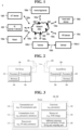
- FIG. 1 illustrates an example of a communication system 1 to which implementations of the present disclosure are applied.
- the communication system 1 applied to the present disclosure includes wireless devices, BSs, and a network.
- the wireless devices represent devices performing communication using RAT (e.g., 5G NR or LTE (e.g., E-UTRA)) and may be referred to as communication/radio/5G devices.
- the wireless devices may include, without being limited to, a robot 100a, vehicles 100b-1 and 100b-2, an extended reality (XR) device 100c, a hand-held device 100d, a home appliance 100e, an Internet of Things (IoT) device 100f, and an artificial intelligence (AI) device/server 400.
- RAT e.g., 5G NR or LTE (e.g., E-UTRA
- XR extended reality
- IoT Internet of Things
- AI artificial intelligence
- the vehicles may include a vehicle having a wireless communication function, an autonomous driving vehicle, and a vehicle capable of performing vehicle-to-vehicle communication.
- the vehicles may include an unmanned aerial vehicle (UAV) (e.g., a drone).
- UAV unmanned aerial vehicle
- the XR device may include an augmented reality (AR)/virtual reality (VR)/mixed reality (MR) device and may be implemented in the form of a head-mounted device (HMD), a head-up display (HUD) mounted in a vehicle, a television, a smartphone, a computer, a wearable device, a home appliance device, a digital signage, a vehicle, a robot, etc.
- AR augmented reality
- VR virtual reality
- MR mixeded reality
- HMD head-mounted device
- HUD head-up display
- the hand-held device may include a smartphone, a smartpad, a wearable device (e.g., a smartwatch or smartglasses), and a computer (e.g., a notebook).
- the home appliance may include a TV, a refrigerator, and a washing machine.
- the IoT device may include a sensor and a smartmeter.
- the BSs and the network may also be implemented as wireless devices and a specific wireless device 200a may operate as a BS/network node with respect to another wireless device.
- the wireless devices 100a to 100f may be connected to a network 300 via BSs 200.
- AI technology may be applied to the wireless devices 100a to 100f and the wireless devices 100a to 100f may be connected to the AI server 400 via the network 300.
- the network 300 may be configured using a 3G network, a 4G (e.g., LTE) network, or a 5G (e.g., NR) network.
- the wireless devices 100a to 100f may communicate with each other through the BSs 200/network 300, the wireless devices 100a to 100f may perform direct communication (e.g., sidelink communication) with each other without passing through the BSs/network.
- the vehicles 100b-1 and 100b-2 may perform direct communication (e.g.
- the IoT device e.g., a sensor
- the IoT device may perform direct communication with other IoT devices (e.g., sensors) or other wireless devices 100a to 100f.
- Wireless communication/connections 150a and 150b may be established between the wireless devices 100a to 100f and the BSs 200 and between the wireless devices 100a to 100f).
- the wireless communication/connections such as UL/DL communication 150a and sidelink communication 150b (or, device-to-device (D2D) communication) may be established by various RATs (e.g., 5G NR).
- the wireless devices and the BSs/wireless devices may transmit/receive radio signals to/from each other through the wireless communication/connections 150a and 150b.
- various configuration information configuring processes various signal processing processes (e.g., channel encoding/decoding, modulation/demodulation, and resource mapping/demapping), and resource allocating processes, for transmitting/receiving radio signals, may be performed based on the various proposals of the present disclosure.
- various signal processing processes e.g., channel encoding/decoding, modulation/demodulation, and resource mapping/demapping
- resource allocating processes for transmitting/receiving radio signals
- FIG. 2 is a block diagram illustrating examples of communication devices capable of performing a method according to the present disclosure.
- a first wireless device 100 and a second wireless device 200 may transmit and/or receive radio signals through a variety of RATs (e.g., LTE and NR).
- ⁇ the first wireless device 100 and the second wireless device 200 ⁇ may correspond to ⁇ the wireless device 100x and the BS 200 ⁇ and/or ⁇ the wireless device 100x and the wireless device 100x ⁇ of FIG. 1 .
- the first wireless device 100 may include one or more processors 102 and one or more memories 104 and additionally further include one or more transceivers 106 and/or one or more antennas 108.
- the processor(s) 102 may control the memory(s) 104 and/or the transceiver(s) 106 and may be configured to implement the afore-described /proposed functions, procedures, and/or methods.
- the processor(s) 102 may process information within the memory(s) 104 to generate first information/signals and then transmit radio signals including the first information/signals through the transceiver(s) 106.
- the processor(s) 102 may receive radio signals including second information/signals through the transceiver(s) 106 and then store information obtained by processing the second information/signals in the memory(s) 104.
- the memory(s) 104 may be connected to the processor(s) 102 and may store a variety of information related to operations of the processor(s) 102.
- the memory(s) 104 may perform a part or all of processes controlled by the processor(s) 102 or store software code including instructions for performing the afore-described/proposed procedures and/or methods.
- the processor(s) 102 and the memory(s) 104 may be a part of a communication modem/circuit/chip designed to implement RAT (e.g., LTE or NR).
- RAT e.g., LTE or NR
- the transceiver(s) 106 may be connected to the processor(s) 102 and transmit and/or receive radio signals through one or more antennas 108. Each of the transceiver(s) 106 may include a transmitter and/or a receiver. The transceiver(s) 106 is used interchangeably with radio frequency (RF) unit(s). In the present disclosure, the wireless device may represent the communication modem/circuit/chip.
- RF radio frequency
- the second wireless device 200 may include one or more processors 202 and one or more memories 204 and additionally further include one or more transceivers 206 and/or one or more antennas 208.
- the processor(s) 202 may control the memory(s) 204 and/or the transceiver(s) 206 and may be configured to implement the afore-described/proposed functions, procedures, and/or methods.
- the processor(s) 202 may process information within the memory(s) 204 to generate third information/signals and then transmit radio signals including the third information/signals through the transceiver(s) 206.
- the processor(s) 202 may receive radio signals including fourth information/signals through the transceiver(s) 106 and then store information obtained by processing the fourth information/signals in the memory(s) 204.
- the memory(s) 204 may be connected to the processor(s) 202 and may store a variety of information related to operations of the processor(s) 202. For example, the memory(s) 204 may perform a part or all of processes controlled by the processor(s) 202 or store software code including instructions for performing the afore-described/proposed procedures and/or methods.
- the processor(s) 202 and the memory(s) 204 may be a part of a communication modem/circuit/chip designed to implement RAT (e.g., LTE or NR).
- RAT e.g., LTE or NR
- the transceiver(s) 206 may be connected to the processor(s) 202 and transmit and/or receive radio signals through one or more antennas 208. Each of the transceiver(s) 206 may include a transmitter and/or a receiver. The transceiver(s) 206 is used interchangeably with RF unit(s). In the present disclosure, the wireless device may represent the communication modem/circuit/chip.
- One or more protocol layers may be implemented by, without being limited to, one or more processors 102 and 202.
- the one or more processors 102 and 202 may implement one or more layers (e.g., functional layers such as a physical (PHY) layer, medium access control (MAC) layer, a radio link control (RLC) layer, a packet data convergence protocol (PDCP) layer, radio resource control (RRC) layer, and a service data adaptation protocol (SDAP) layer).
- layers e.g., functional layers such as a physical (PHY) layer, medium access control (MAC) layer, a radio link control (RLC) layer, a packet data convergence protocol (PDCP) layer, radio resource control (RRC) layer, and a service data adaptation protocol (SDAP) layer).
- PHY physical
- MAC medium access control
- RLC radio link control
- PDCP packet data convergence protocol
- RRC radio resource control
- SDAP service data adaptation protocol
- the one or more processors 102 and 202 may generate one or more protocol data units (PDUs) and/or one or more service data units (SDUs) according to the functions, procedures, proposals, and/or methods disclosed in the present disclosure.
- the one or more processors 102 and 202 may generate messages, control information, data, or information according to the functions, procedures, proposals, and/or methods disclosed in the present disclosure.
- the one or more processors 102 and 202 may generate signals (e.g., baseband signals) including PDUs, SDUs, messages, control information, data, or information according to the functions, procedures, proposals, and/or methods disclosed in the present disclosure and provide the generated signals to the one or more transceivers 106 and 206.
- the one or more processors 102 and 202 may receive the signals (e.g., baseband signals) from the one or more transceivers 106 and 206 and acquire the PDUs, SDUs, messages, control information, data, or information according to the functions, procedures, proposals, and/or methods disclosed in the present disclosure.
- signals e.g., baseband signals
- the one or more processors 102 and 202 may be referred to as controllers, microcontrollers, microprocessors, or microcomputers.
- the one or more processors 102 and 202 may be implemented by hardware, firmware, software, or a combination thereof.
- ASICs application specific integrated circuits
- DSPs digital signal processors
- DSPDs digital signal processing devices
- PLDs programmable logic devices
- FPGAs field programmable gate arrays
- the functions, procedures, proposals, and/or methods disclosed in the present disclosure may be implemented using firmware or software, and the firmware or software may be configured to include the modules, procedures, or functions.
- Firmware or software configured to perform the functions, procedures, proposals, and/or methods disclosed in the present disclosure may be included in the one or more processors 102 and 202 or stored in the one or more memories 104 and 204 so as to be driven by the one or more processors 102 and 202.
- the functions, procedures, proposals, and/or methods disclosed in the present disclosure may be implemented using firmware or software in the form of code, commands, and/or a set of commands.
- the one or more memories 104 and 204 may be connected to the one or more processors 102 and 202 and store various types of data, signals, messages, information, programs, code, commands, and/or instructions.
- the one or more memories 104 and 204 may be configured by read-only memories (ROMs), random access memories (RAMs), electrically erasable programmable read-only memories (EPROMs), flash memories, hard drives, registers, cash memories, computer-readable storage media, and/or combinations thereof.
- the one or more memories 104 and 204 may be located at the interior and/or exterior of the one or more processors 102 and 202.
- the one or more memories 104 and 204 may be connected to the one or more processors 102 and 202 through various technologies such as wired or wireless connection.
- the one or more transceivers 106 and 206 may transmit user data, control information, and/or radio signals/channels, mentioned in the methods and/or operational flowcharts of the present disclosure, to one or more other devices.
- the one or more transceivers 106 and 206 may receive user data, control information, and/or radio signals/channels, mentioned in the functions, procedures, proposals, methods, and/or operational flowcharts disclosed in the present disclosure, from one or more other devices.
- the one or more transceivers 106 and 206 may be connected to the one or more processors 102 and 202 and transmit and receive radio signals.
- the one or more processors 102 and 202 may perform control so that the one or more transceivers 106 and 206 may transmit user data, control information, or radio signals to one or more other devices.
- the one or more processors 102 and 202 may perform control so that the one or more transceivers 106 and 206 may receive user data, control information, or radio signals from one or more other devices.
- the one or more transceivers 106 and 206 may be connected to the one or more antennas 108 and 208.
- the one or more transceivers 106 and 206 may be configured to transmit and receive user data, control information, and/or radio signals/channels, mentioned in the functions, procedures, proposals, methods, and/or operational flowcharts disclosed in the present disclosure, through the one or more antennas 108 and 208.
- the one or more antennas may be a plurality of physical antennas or a plurality of logical antennas (e.g., antenna ports).
- the one or more transceivers 106 and 206 may convert received radio signals/channels etc. from RF band signals into baseband signals in order to process received user data, control information, radio signals/channels, etc. using the one or more processors 102 and 202.
- the one or more transceivers 106 and 206 may convert the user data, control information, radio signals/channels, etc. processed using the one or more processors 102 and 202 from the base band signals into the RF band signals. To this end, the one or more transceivers 106 and 206 may include (analog) oscillators and/or filters.
- FIG. 3 illustrates another example of a wireless device capable of performing implementation(s) of the present disclosure.
- wireless devices 100 and 200 may correspond to the wireless devices 100 and 200 of FIG. 2 and may be configured by various elements, components, units/portions, and/or modules.
- each of the wireless devices 100 and 200 may include a communication unit 110, a control unit 120, a memory unit 130, and additional components 140.
- the communication unit may include a communication circuit 112 and transceiver(s) 114.
- the communication circuit 112 may include the one or more processors 102 and 202 and/or the one or more memories 104 and 204 of FIG. 2 .
- the transceiver(s) 114 may include the one or more transceivers 106 and 206 and/or the one or more antennas 108 and 208 of FIG. 2 .
- the control unit 120 is electrically connected to the communication unit 110, the memory 130, and the additional components 140 and controls overall operation of the wireless devices. For example, the control unit 120 may control an electric/mechanical operation of the wireless device based on programs/code/commands/information stored in the memory unit 130.
- the control unit 120 may transmit the information stored in the memory unit 130 to the exterior (e.g., other communication devices) via the communication unit 110 through a wireless/wired interface or store, in the memory unit 130, information received through the wireless/wired interface from the exterior (e.g., other communication devices) via the communication unit 110.
- the additional components 140 may be variously configured according to types of wireless devices.
- the additional components 140 may include at least one of a power unit/battery, input/output (I/O) unit, a driving unit, and a computing unit.
- the wireless device may be implemented in the form of, without being limited to, the robot (100a of FIG. 1 ), the vehicles (100b-1 and 100b-2 of FIG. 1 ), the XR device (100c of FIG. 1 ), the hand-held device (100d of FIG. 1 ), the home appliance (100e of FIG. 1 ), the IoT device (100f of FIG.
- the wireless device may be used in a mobile or fixed place according to a use-case/service.
- the entirety of the various elements, components, units/portions, and/or modules in the wireless devices 100 and 200 may be connected to each other through a wired interface or at least a part thereof may be wirelessly connected through the communication unit 110.
- the control unit 120 and the communication unit 110 may be connected by wire and the control unit 120 and first units (e.g., 130 and 140) may be wirelessly connected through the communication unit 110.
- Each element, component, unit/portion, and/or module within the wireless devices 100 and 200 may further include one or more elements.
- the control unit 120 may be configured by a set of one or more processors.
- control unit 120 may be configured by a set of a communication control processor, an application processor, an electronic control unit (ECU), a graphical processing unit, and a memory control processor.
- memory 130 may be configured by a random access memory (RAM), a dynamic RAM (DRAM), a read-only memory (ROM)), a flash memory, a volatile memory, a non-transitory memory, and/or a combination thereof.
- the at least one memory may store instructions or programs, and the instructions or programs may cause, when executed, at least one processor operably connected to the at least one memory to perform operations according to some embodiments or implementations of the present disclosure.
- a computer readable storage medium may store at least one instruction or program, and the at least one instruction or program may cause, when executed by at least one processor, the at least one processor to perform operations according to some embodiments or implementations of the present disclosure.
- a processing device or apparatus may include at least one processor, and at least one computer memory operably connected to the at least one processor.
- the at least one computer memory may store instructions or programs, and the instructions or programs may cause, when executed, the at least one processor operably connected to the at least one memory to perform operations according to some embodiments or implementations of the present disclosure.
- a communication device of the present disclosure includes at least one processor; and at least one computer memory operably connected to the at least one processor and configured to store instructions for causing, when executed, the at least one processor to perform operations according to example(s) of the present disclosure described later.
- FIG. 4 illustrates an example of a frame structure used in a 3GPP-based wireless communication system.
- the frame structure of FIG. 4 is purely exemplary and the number of subframes, the number of slots, and the number of symbols, in a frame, may be variously changed.
- different OFDM numerologies e.g., subcarrier spacings (SCSs)
- SCSs subcarrier spacings
- the (absolute time) duration of a time resource including the same number of symbols e.g., a subframe, a slot, or a transmission time interval (TTI)
- TTI transmission time interval
- the symbol may include an OFDM symbol (or cyclic prefix - OFDM (CP-OFDM) symbol) and an SC-FDMA symbol (or discrete Fourier transform-spread-OFDM (DFT-s-OFDM) symbol).
- OFDM symbol or cyclic prefix - OFDM (CP-OFDM) symbol
- SC-FDMA symbol or discrete Fourier transform-spread-OFDM (DFT-s-OFDM) symbol.
- DFT-s-OFDM discrete Fourier transform-spread-OFDM
- Each half-frame includes 5 subframes and a duration T sf of a single subframe is 1 ms.
- Subframes are further divided into slots and the number of slots in a subframe depends on a subcarrier spacing.
- Each slot includes 14 or 12 OFDM symbols based on a cyclic prefix. In a normal CP, each slot includes 14 OFDM symbols and, in an extended CP, each slot includes 12 OFDM symbols.
- the table below shows the number of OFDM symbols ( N slot symb ) per slot, the number of slots ( N frame,u slot ) per frame, and the number of slots ( N subframe,u slot ) per subframe.
- Table 1 u N slot symb N frame,u slot N subframe,u slot 0 14 10 1 1 14 20 2 2 14 40 4 3 14 80 8 4 14 160 16
- NR frequency bands are defined as two types of frequency ranges, i.e., FR1 and FR2.
- FR2 is also referred to as millimeter wave (mmW).
- mmW millimeter wave
- Table 3 Frequency Range designation Corresponding frequency range Subcarrier Spacing FR1 410MHz - 7125MHz 15, 30, 60kHz FR2 24250MHz - 52600MHz 60, 120, 240kHz
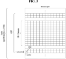
- FIG. 5 illustrates a resource grid of a slot.
- the slot includes multiple (e.g., 14 or 12) symbols in the time domain.
- a resource grid of N size,u grid,x * N RB sc subcarriers and N subframe,u symb OFDM symbols is defined, starting at a common resource block (CRB) N start,u grid indicated by higher layer signaling (e.g. RRC signaling), where N size,u grid,x is the number of resource blocks (RBs) in the resource grid and the subscript x is DL for downlink and UL for uplink.
- N RB sc is the number of subcarriers per RB. In the 3GPP-based wireless communication system, N RB sc is typically 12.
- Each element in the resource grid for the antenna port p and the subcarrier spacing configuration u is referred to as a resource element (RE) and one complex symbol may be mapped to each RE.
- Each RE in the resource grid is uniquely identified by an index k in the frequency domain and an index l representing a symbol location relative to a reference point in the time domain.
- an RB is defined by 12 consecutive subcarriers in the frequency domain.
- RBs are classified into CRBs and physical resource blocks (PRBs).
- the CRBs are numbered from 0 upwards in the frequency domain for the subcarrier spacing configuration u.
- the center of subcarrier 0 of CRB 0 for the subcarrier spacing configuration u is equal to 'Point A' which serves as a common reference point for RB grids.
- the PRBs are defined within a bandwidth part (BWP) and numbered from 0 to N size BWP,i -1, where i is a number of the BWP.
- BWP bandwidth part
- n PRB n CRB + N size BWP,i , where N size BWP,i is a CRB in which the BWP starts relative to CRB 0.
- the BWP includes a plurality of consecutive RBs in the frequency domain.
- a carrier may include a maximum of N (e.g., 5) BWPs.
- the UE may be configured to have one or more BWPs on a given component carrier. Data communication is performed through an activated BWP and only a predetermined number of BWPs (e.g., one BWP) among BWPs configured for the UE may be active on the component carrier.
- a PDCCH carries DCI.
- the PDCCH i.e., DCI
- DL-SCH downlink shared channel
- UL-SCH uplink shared channel
- PCH paging information about a paging channel
- system information about the DL-SCH information about resource allocation for a control message, such as a random access response (RAR) transmitted on a PDSCH, of a layer (hereinafter, higher layer) positioned higher than a physical layer among protocol stacks of the UE/BS, a transmit power control command, information about activation/deactivation of configured scheduling (CS), etc.
- RAR random access response
- DCI including resource allocation information on the DL-SCH is called PDSCH scheduling DCI
- DCI including resource allocation information on the UL-SCH is called PUSCH scheduling DCI.
- the DCI includes a cyclic redundancy check (CRC).
- the CRC is masked/scrambled with various identifiers (e.g., radio network temporary identifier (RNTI)) according to an owner or usage of the PDCCH. For example, if the PDCCH is for a specific UE, the CRS is masked with a UE identifier (e.g., cell-RNTI (C-RNTI)).
- C-RNTI cell-RNTI
- the CRC is masked with a paging RNTI (P-RNTI). If the PDCCH is for system information (e.g., system information block (SIB)), the CRC is masked with a system information RNTI (SI-RNTI). If the PDCCH is for a random access response, the CRC is masked with a random access-RNTI (RA-RNTI).
- SIB system information block
- RA-RNTI random access-RNTI
- Cross-carrier scheduling with a carrier indicator field may allow a PDCCH on a serving cell to schedule resources on another serving cell.
- a PDSCH on a serving cell schedules a PDSCH or a PUSCH on the serving cell, it is referred to as self-carrier scheduling.
- the BS may provide information about a cell scheduling the cell to the UE. For example, the BS may inform the UE whether a serving cell is scheduled by a PDCCH on another (scheduling) cell or scheduled by the serving cell.
- the BS may inform the UE which cell signals DL assignments and UL grants for the serving cell.
- a cell carrying a PDCCH is referred to as a scheduling cell
- a cell where transmission of a PUSCH or a PDSCH is scheduled by DCI included in the PDCCH, that is, a cell carrying the PUSCH or PDSCH scheduled by the PDCCH is referred to as a scheduled cell.
- the PDCCH is transmitted through a control resource set (CORESET).
- CORESET control resource set
- One or more CORESETs may be configured for a UE.
- the CORESET is determined based on the following parameters.
- a CORESET which is a set of time-frequency resources on which the UE is capable of monitoring a PDCCH, may be defined and/or configured.
- the UE may be configured with one or more CORESETs.
- the CORESET has a time duration of one to three OFDM symbols and includes a set of PRBs.
- the PRBs included in the CORESET and the CORESET duration may be provided to the UE through higher layer (e.g., RRC) signaling.
- the UE may monitor a set of PDCCH candidates in configured CORESET(s) according to corresponding search space sets. In the present disclosure, monitoring implies decoding (blind decoding) of each PDCCH candidate based on monitored DCI formats.
- the MIB on a PBCH provides the UE with parameters (e.g., CORESET #0 configuration) for monitoring a PDCCH that schedules a PDSCH carrying SIB1.
- the PBCH may indicate that there is no associated SIB1.
- the UE may be provided with not only a frequency range where the UE is allowed to assume that there is no SSB associated with SSB1 but also may be provided with another frequency range where the UE is allowed to discover an SSB associated with SIB1.
- CORESET #0 which is a CORESET for scheduling at least SIB1, may be configured through the MIB or dedicated RRC signaling.
- the set of the PDCCH candidates that the UE monitors is defined in terms of PDCCH search space sets.
- the search space sets may be common search space (CSS) sets or UE-specific search space (USS) sets.
- Each CORESET configuration is associated with one or more search space sets and each search space set is associated with one CORESET configuration.
- a search space set is determined based on the following parameters provided to the UE by the BS.
- a UE monitors PDCCH candidates in PDCCH monitoring occasions only.
- the UE determines a PDCCH monitoring occasion from the PDCCH monitoring periodicity, the PDCCH monitoring offset, and the PDCCH monitoring pattern within a slot.
- the parameter monitoringSymbolsWithinSlot may indicate the first symbol(s) for PDCCH monitoring in the slots configured for PDCCH monitoring (e.g., see monitoringSlotPeriodicityAndOffset and duration ).
- monitoringSymbolsWithinSlot is a 14-bit parameter
- the most significant (leftmost) bit may represent the first OFDM symbol in the slot
- the second most significant (leftmost) bit may represent the second OFDM symbol in the slot.
- the bits of monitoringSymbolsWithinSlot may represent the 14 OFDM symbols of the slot, respectively.
- bit(s) set to 1 among the bits in monitoringSymbolsWithinSlot may identify the first symbol(s) of the CORESET in the slot.
- Table 4 Search Space Type RNTI Use Case Type0-PDCCH Common SI-RNTI on a primary cell SIB Decoding Type0A-PDCCH Common SI-RNTI on a primary cell SIB decoding Type1-PDCCH Common RA-RNTI or TC-RNTI on a primary cell Msg2, Msg4 decoding in RACH Type2-PDCCH Common P-RNTI on a primary cell Paging Decoding Type3-PDCCH Common INT-RNTI, SFI-RNTI, TPC-PUSCH-RNTI, TPC-PUCCH-RNTI, TPC-SRS-RNTI, C-RNTI, MCS-C-RNTI or CS-RNTI(s) UE Specific UE Specific C-RNTI, MCS-C-RNTI or CS-RNTI(s) User specific PDSCH decoding
- Table 5 DCI format Usage 0_0 Scheduling of PUSCH in one cell 0_1 Scheduling of PUSCH in one cell 1_0 Scheduling of PDSCH in one cell 1_1 Scheduling of PDSCH in one cell 2_0 Notifying a group of UEs of the slot format 2_1 Notifying a group of UEs of the PRB(s) and OFDM symbol(s) where UE may assume no transmission is intended for the UE 2_2 Transmission of TPC commands for PUCCH and PUSCH 2_3 Transmission of a group of TPC commands for SRS transmissions by one or more UEs
- DCI format 0_0 may be used to schedule a TB-based (or TB-level) PUSCH
- DCI format 0_1 may be used to schedule a TB-based (or TB-level) PUSCH or a code block group (CBG)-based (or CBG-level) PUSCH
- DCI format 1_0 may be used to schedule a TB-based (or TB-level) PDSCH
- DCI format 1_1 may be used to schedule a TB-based (or TB-level) PDSCH or a CBG-based (or CBG-level) PDSCH.
- DCI format 0_0 and DCI format 1_0 have fixed sizes after the BWP size is initially given by RRC.
- DCI format 0_0 and DCI format 1_0 are fixed in size in fields other than a frequency domain resource assignment (FDRA) field, and the FDRA field may vary in size by configuration of a related parameter by the BS.
- the size of the DCI field may be changed by various RRC reconfigurations by the BS.
- DCI format 2_0 may be used to transfer dynamic slot format information (e.g., SFI DCI) to the UE
- DCI format 2_1 may be used to transfer downlink pre-emption information to the UE.
- DCI format 2_0 and/or DCI format 2_1 may be transferred to UEs within a corresponding group via a group common PDCCH, which is a PDCCH transferred to UEs defined as one group.
- a PDSCH is a physical layer UL channel for UL data transport.
- the PDSCH carries DL data (e.g., DL-SCH transport block) and is subjected to modulation such as quadrature phase shift keying (QPSK), 16 quadrature amplitude modulation (QAM), 64 QAM, 256 QAM, etc.
- QPSK quadrature phase shift keying
- QAM 16 quadrature amplitude modulation
- a codeword is generated by encoding a transport block (TB).
- the PDSCH may carry a maximum of two codewords. Scrambling and modulation mapping per codeword may be performed and modulation symbols generated from each codeword may be mapped to one or more layers. Each layer is mapped to a radio resource together with a DMRS and generated as an OFDM symbol signal.
- the PDSCH may be dynamically scheduled by the PDCCH (dynamic scheduling) or semi-statically scheduled based on higher layer (e.g., RRC) signaling (and/or Layer 1 (L1) signaling (e.g., PDCCH)) (Configured Scheduling (CS)). Therefore, in dynamic scheduling, PDSCH transmission is accompanied by the PDCCH, but in the CS, PDSCH transmission is not accompanied by the PDCCH.
- the CS includes semi-persistent scheduling (SPS).
- a PUCCH is a physical layer UL channel for uplink control information (UCI) transmission.
- the PUCCH carries UCI.
- the UCI includes the following information.
- PUCCH resources configured/indicated for/to the UE by the BS for HARQ-ACK, SR, and CSI transmission are referred to as an HARQ-ACK PUCCH resource, an SR PUCCH resource, and a CSI PUCCH resource, respectively.
- PUCCH formats may be defined as follows according to UCI payload sizes and/or transmission lengths (e.g., the number of symbols included in PUCCH resources). In regard to the PUCCH formats, reference may also be made to Table 6.
- Configuration for PUCCH format 3 includes the following parameters for a corresponding PUCCH resource: the number of PRBs, the number of symbols for PUCCH transmission, and/or the first symbol for PUCCH transmission.
- the table below shows the PUCCH formats.
- the PUCCH formats may be divided into short PUCCH formats (formats 0 and 2) and long PUCCH formats (formats 1, 3, and 4) according to PUCCH transmission length.
- Table 6 PUCCH format Length in OFDM symbols N PUCCH symb Number of bits Usage Etc.
- SR Sequence selection 1 4-14 ⁇ 2 HARQ, [SR] Sequence modulation 2 1-2 >2 HARQ, CSI, [SR] CP-OFDM 3 4-14 >2 HARQ, CSI, [SR] DFT-s-OFDM(no UE multiplexing) 4 4-14 >2 HARQ, CSI, [SR] DFT-s-OFDM(Pre DFT OCC)
- a PUCCH resource may be determined according to a UCI type (e.g., A/N, SR, or CSI).
- a PUCCH resource used for UCI transmission may be determined based on a UCI (payload) size.
- the BS may configure a plurality of PUCCH resource sets for the UE, and the UE may select a specific PUCCH resource set corresponding to a specific range according to the range of the UCI (payload) size (e.g., numbers of UCI bits).
- the UE may select one of the following PUCCH resource sets according to the number of UCI bits, N UCI .
- K represents the number of PUCCH resource sets (K>1) and N i represents a maximum number of UCI bits supported by PUCCH resource set #i.
- PUCCH resource set #1 may include resources of PUCCH formats 0 to 1
- the other PUCCH resource sets may include resources of PUCCH formats 2 to 4.
- Configuration for each PUCCH resource includes a PUCCH resource index, a start PRB index, and configuration for one of PUCCH format 0 to PUCCH format 4.
- the UE is configured with a code rate for multiplexing HARQ-ACK, SR, and CSI report(s) within PUCCH transmission using PUCCH format 2, PUCCH format 3, or PUCCH format 4, by the BS through a higher layer parameter maxCodeRate.
- the higher layer parameter maxCodeRate is used to determine how to feed back the UCI on PUCCH resources for PUCCH format 2, 3, or 4.
- a PUCCH resource to be used for UCI transmission in a PUCCH resource set may be configured for the UE through higher layer signaling (e.g., RRC signaling).
- the UCI type is HARQ-ACK for a semi-persistent scheduling (SPS) PDSCH
- the PUCCH resource to be used for UCI transmission in the PUCCH resource set may be configured for the UE through higher layer signaling (e.g., RRC signaling).
- the UCI type is HARQ-ACK for a PDSCH scheduled by DCI
- the PUCCH resource to be used for UCI transmission in the PUCCH resource set may be scheduled by the DCI.
- the BS may transmit the DCI to the UE on a PDCCH and indicate a PUCCH resource to be used for UCI transmission in a specific PUCCH resource set by an ACK/NACK resource indicator (ARI) in the DCI.
- the ARI may be used to indicate a PUCCH resource for ACK/NACK transmission and also be referred to as a PUCCH resource indicator (PRI).
- the DCI may be used for PDSCH scheduling and the UCI may include HARQ-ACK for a PDSCH.
- the BS may configure a PUCCH resource set including a larger number of PUCCH resources than states representable by the ARI by (UE-specific) higher layer (e.g., RRC) signaling for the UE.
- the ARI may indicate a PUCCH resource subset of the PUCCH resource set and which PUCCH resource in the indicated PUCCH resource subset is to be used may be determined according to an implicit rule based on transmission resource information about the PDCCH (e.g., the starting CCE index of the PDCCH).
- the UE For UL-SCH data transmission, the UE should include UL resources available for the UE and, for DL-SCH data reception, the UE should include DL resources available for the UE.
- the UL resources and the DL resources are assigned to the UE by the BS through resource allocation.
- Resource allocation may include time domain resource allocation (TDRA) and frequency domain resource allocation (FDRA).
- TDRA time domain resource allocation
- FDRA frequency domain resource allocation
- UL resource allocation is also referred to as a UL grant and DL resource allocation is referred to as DL assignment.
- the UL grant is dynamically received by the UE on the PDCCH or in RAR or semi-persistently configured for the UE by the BS through RRC signaling.
- DL assignment is dynamically received by the UE on the PDCCH or semi-persistently configured for the UE by the BS through RRC signaling.
- the BS may dynamically allocate UL resources to the UE through PDCCH(s) addressed to a cell radio network temporary Identifier (C-RNTI).
- C-RNTI cell radio network temporary Identifier
- the UE monitors the PDCCH(s) in order to discover possible UL grant(s) for UL transmission.
- the BS may allocate the UL resources using a configured grant to the UE.
- Two types of configured grants, Type 1 and Type 2 may be used.
- the BS directly provides the configured UL grant (including periodicity) through RRC signaling.
- the BS may configure a periodicity of an RRC-configured UL grant through RRC signaling and signal, activate, or deactivate the configured UL grant through the PDCCH addressed to a configured scheduling RNTI (CS-RNTI).
- CS-RNTI configured scheduling RNTI
- the PDCCH addressed to the CS-RNTI indicates that the corresponding UL grant may be implicitly reused according to the configured periodicity through RRC signaling until
- the BS may dynamically allocate DL resources to the UE through PDCCH(s) addressed to the C-RNTI.
- the UE monitors the PDCCH(s) in order to discover possible DL grant(s).
- the BS may allocate the DL resources to the UE using SPS.
- the BS may configure a periodicity of configured DL assignment through RRC signaling and signal, activate, or deactivate the configured DL assignment through the PDCCH addressed to the CS-RNTI.
- the PDCCH addressed to the CS-RNTI indicates that the corresponding DL assignment may be implicitly reused according to the configured periodicity through RRC signaling until deactivation.
- the PUSCH carries UL data (e.g., UL-SCH TB) and/or UL control information (UCI) and is transmitted based on a cyclic prefix-orthogonal frequency division multiplexing (CP-OFDM) waveform or a discrete Fourier transform-spread-OFDM (DFT-s-OFDM) waveform.
- CP-OFDM cyclic prefix-orthogonal frequency division multiplexing
- DFT-s-OFDM discrete Fourier transform-spread-OFDM
- the UE may transmit the PUSCH based on the CP-OFDM waveform
- the UE may transmit the PUSCH based on the CP-OFDM waveform or the DFT-s-OFDM waveform.
- the PUSCH may be dynamically scheduled by the PDCCH (dynamic scheduling) or semi-statically scheduled based on higher layer (e.g., RRC) signaling (and/or Layer 1 (L1) signaling (e.g., PDCCH)) (Configured Scheduling (CS)). Therefore, in dynamic scheduling, PUSCH transmission is accompanied by the PDCCH, but in the CS, PUSCH transmission is not accompanied by the PDCCH.
- the CS includes Type-1 configured grant (CG) PUSCH transmission and Type-2 CG PUSCH transmission.
- Type-1 CG all parameters for PUSCH transmission are signaled via a higher layer.
- Type-2 CG some of the parameters for PUSCH transmission are signaled via a higher layer and the remaining parameters are signaled by the PDCCH.
- PUSCH transmission is not accompanied by the PDCCH.
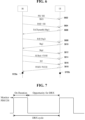
- FIG. 6 illustrates a network communication process for performing implementation(s) of the present disclosure.
- FIG. 6 illustrates an initial network connection and subsequent communication processes.
- the UE may perform a network communication process for performing procedures and/or methods described in the present disclosure.
- the UE may receive and store, in a memory system, information and configuration information necessary to perform the procedures and/or methods described in the present disclosure while performing an access to a network (e.g., a BS).
- the configuration information required to perform implementation(s) according to the present disclosure may be received via higher layer (e.g., RRC layer or MAC layer) signaling.
- a physical channel and a reference signal may be transmitted using beamforming.
- a beam management process may be involved to align beams between the BS and the UE.
- signals may be transmitted/received using beamforming.
- RRC radio resource control
- beam alignment may be performed based on SSB.
- RRC_ONNECTED mode beam alignment may be performed based on CSI-RS (in DL) and SRS (in UL).
- a beam-related operation may be omitted in the description below.
- the BS may transmit the SSB periodically (S602).
- the SSB includes PSS/SSS/PBCH.
- the SSB may be transmitted using beam sweeping.
- the BS may transmit remaining minimum system information (RMSI) and other system information (OSI) (S604).
- the RMSI may include information required for the UE to initially access the BS (e.g., PRACH configuration information).
- the UE performs SSB detection and then identifies the best SSB.
- the UE may transmit a RACH preamble (Msg1) to the BS by using a PRACH resource linked/corresponding to an index (i.e., beam) of the best SSB (S606).
- Msg1 RACH preamble
- a beam direction of the RACH preamble is related to the PRACH resource.
- the association between the PRACH resource (and/or RACH preamble) and SSB (index) may be established via system information (e.g., RMSI).
- the BS may transmit a random access response (RAR) (Msg2) in response to the RACH preamble (S608)
- the UE may transmit Msg3 (e.g., RRC connection request) by using the UL grant in the RAR (S610), and the BS may transmit a contention resolution message (Msg4) (S620).
- Msg4 may include RRC connection setup.
- subsequent beam alignment may be performed based on SSB/CSI-RS (in DL) and SRS (in UL).
- the UE may receive the SSB/CSI-RS (S614).
- the SSB/CSI-RS may be used by the UE to generate a beam/CSI report.
- the BS may request the beam/CSI report from the UE through DCI (S616).
- the UE may generate the beam/CSI report based on the SSB/CSI-RS and transmit the generated beam/CSI report to the BS through the PUSCH/PUCCH (S618).
- the beam/CSI report may include a beam measurement result, and information about a preferred beam.
- the BS and the UE may switch a beam based on the beam/CSI report (S620a and S620b).
- the BS and the UE may perform the procedures and/or methods described in the present disclosure.
- the UE and the BS may process information in the memory and transmit a wireless signal or process a received wireless signal and store the signal in the memory based on configuration information obtained during a network access process (e.g., a system information obtaining process or an RRC connection process via RACH) according to the proposal of the present disclosure.
- the wireless signal may include at least one of the PDCCH, the PDSCH, and the reference signal (RS) for DL, and at least one of the PUCCH, the PUSCH, and the SRS for UL.
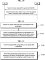
- FIG. 7 illustrates a discontinuous reception (DRX) operation.
- FIG. 7 illustrates a DRX cycle for a UE in an RRC_CONNECTED state.
- the UE may perform the DRX operation while performing a process and/or method according to some implementations of the present disclosure.
- a UE configured with the DRX may reduce power consumption by receiving a DL signal discontinuously.
- the DRX operation may be performed in an RRC_IDLE state, an RRC_INACTIVE state, and an RRC_CONNECTED state.
- the DRX is used to discontinuously receive a paging signal.
- RRC_CONNECTED DRX DRX performed in RRC_CONNECTED state (RRC_CONNECTED DRX) is described.
- a DRX cycle is configured with an ON duration and an opportunity for DRX.
- the DRX cycle defines a time interval over which the ON duration is repeated periodically.
- the ON duration represents a time duration in which the UE monitors to receive the PDCCH.
- the UE performs PDCCH monitoring during the ON duration.
- the PDCCH is successfully detected while monitoring the PDCCH
- the UE starts an inactivity timer and maintains the timer in an awake state.
- the UE enters a sleep state after the ON duration ends.
- PDCCH monitoring/reception may be performed discontinuously in the time domain when performing methods and/or procedures according to some implementations of the present disclosure.
- the PDCCH reception occasion e.g., slot having PDCCH search space
- the PDCCH monitoring/reception may be performed continuously in the time domain when performing methods and/or procedures according to some implementations of the present disclosure.
- the PDCCH reception opportunity e.g., slot having PDCCH search space
- PDCCH monitoring may be limited during the time duration configured as a measurement gap regardless of whether the DRX is configured.
- DRX configuration information is received via higher layer (e.g. RRC) signaling, and whether the DRX is turned on/off is controlled by a DRX command of the MAC layer.
- RRC higher layer
- the UE may perform PDCCH monitoring discontinuously as illustrated in FIG. 7 .
- Table 7 Type of signals UE procedure 1st step RRC signalling (MAC-CellGroupConfig) - Receive DRX configuration information 2nd Step MAC CE ((Long) DRX command MAC CE) - Receive DRX command 3rd Step - - Monitor a PDCCH during an on-duration of a DRX cycle
- MAC-CellGroupConfig includes configuration information required to configure MAC parameters for a cell group.
- MAC-CellGroupConfig may also include DRX configuration information.
- MAC-CellGroupConfig may include the following parameter information to define the DRX.
- a value in multiples of the short DRX cycle may be configured by drx-CycleTimer.
- the value of n may correspond to n*drx-ShortCycle.
- the UE may perform PDCCH monitoring on serving cells within a DRX group if the DRX group is within the active time.
- the DRX group refers to a group of serving cells that are configured by RRC and have the same DRX active time.
- the Active Time for serving Cells in a DRX group includes the time while i) drx-onDurationTimer or drx-InactivityTimer configured for the DRX group is running, or ii) drx-RetransmissionTimerDL or drx-RetransmissionTimerUL is running on any serving Cell in the DRX group; or ra-ContentionResoultionTimer or msgB-RsponseWindow is running; or a PDCCH indicating a new transmission addressed to the C-RNTI of a MAC entity of the UE has not been received after successful reception of a random access response for the Random Access Preamble not selected by the MAC entity among the contention-based random access preambles.
- FIG. 8 illustrates a case in which a long DRX cycle and a short DRX cycle are configured. Specifically, FIG. 8 shows a case in which drx-ShortCycleTimer is set to 2.
- the BS may configure a long DRX cycle and an additional short DRX cycle, which is shorter than the long DRX cycle. If no short DRX cycle is configured, the UE may follow the long DRX cycle. When configuring the short DRX cycle, the BS may set the duration of the long DRX cycle to be a positive integer multiple of the short DRX cycle. If there is no data activity during the on-duration of the long DRX cycle, the UE may follow the long DRX cycle as if no short DRX cycle is configured.
- the UE switches to the short DRX cycle and follows the short DRX cycle for a certain period of time (e.g., while drx-ShortCycleTimer is running).
- the UE switches from short DRX cycles each having the duration by drx-ShortCycleTimer to the long DRX cycle.
- the following enhancement techniques are considered to improve the energy saving capability of the BS in terms of transmission and reception in the corresponding item.
- FIG. 9 illustrates network energy saving (NES) according to the present disclosure.
- 3GPP RAN WG1 defines an energy consumption model and simulation methodology for the BS to show that energy consumption gains are to be obtained by applying NES technology.
- a sleep state and active state of the BS are defined and a transition method for each state is determined.
- a relative power value consumed by the BS in each state, a time required for state transition, and energy are modeled.
- the BS In a sleep state, the BS neither transmits nor receives.
- an active state the BS performs transmission and/or reception.
- 3GPP RAN WG1 for NES may be divided into four domains (time, frequency, space, and power domains) as shown in the following table, and specific technologies for each domain are as shown in the following table.
- a UE-common signal e.g., SSB, SIB, or paging
- UE-specific signal e.g., CSI-RS
- Table 8 Time domain techniques Adaptation of common signals and channels Dynamic adaptation of UE specific signals and channels Wake up of gNB triggered by UE wake up signal Adaptation of DTX/DRX Adaptation of SSB/SIB1 Frequency domain techniques Multi-carrier energy saving enhancements Dynamic adaptation of bandwidth part of UE(s) within a carrier Dynamic adaptation of bandwidth of active BWP Spatial domain techniques Dynamic adaptation of spatial elements TRP muting/adaptation in multi-TRP operation Power domain techniques Adaptation of transmission power of signals and channels Enhancements to assist gNB digital pre-distortion Adaptation of transceiver processing algorithm PA backoff adaptation UE post-distortion
- NES technologies discussed in the 3GPP RAN WG2 include a method for NES-capable UEs or existing NR UEs to access an NES cell, and an efficient handover method for UEs accessing NES cells.
- the UE may continuously monitor the PDCCH to check if there is a transmission scheduled for the UE in each configured search space (SS). However, if this scheduling is not always present, a battery of the UE may be quickly drained due to unnecessary PDCCH monitoring every time. Therefore, the BS may configure connected mode discontinuous reception (C-DRX) to obtain a power saving effect of the UE by configuring a time duration (ON duration) during which PDCCH monitoring is performed and a duration (OFF duration) during which PDCCH monitoring is not performed.
- C-DRX connected mode discontinuous reception
- the UE performs PDCCH monitoring in periodically configured ON duration to check if there is DL/UL to receive/transmit, and when a PDCCH is received, the UE performs DL reception or UL transmission as instructed.
- UL of the UE regardless of C-DRX, when there is data to be transmitted in a UL buffer, the UE may wake up from a sleep mode and transmit SR, and in the case of a UE in an idle mode, the UE may operate in idle mode DRX (I-DRX) that periodically performs paging monitoring and enters sleep again if the UE is not a target UE.
- I-DRX idle mode DRX
- a UE operating in a sleep mode may mean that the UE operates regardless of an active time determined by C-DRX or that the UE operates in a period other than the active time determined by C-DRX.
- a time duration configured as ON and OFF durations is repeated, which is called a DRX cycle
- a length of the DRX cycle is defined as a time from a starting point of the ON duration to a starting point of a next ON duration, and there are a long DRX cycle and a short DRX cycle.
- the latency may increase because the BS needs to wait until the next ON duration of the UE when a PDSCH to be transmitted occurs immediately after an end of a specific ON duration of the UE.
- the UE does not transmit P-CSI or SRS during the OFF duration, and thus the resource may be allocated to another UE to increase resource utilization, and the BS may also operate in energy saving mode to save power during the OFF duration of the UE.
- a long DRX cycle and a short DRX cycle may be configured simultaneously, and the long DRX cycle may be configured to be an integer multiple of the short DRX cycle.
- the On duration timer values of the long DRX cycle and the short DRX cycle may be equal to each other.
- an operation may be performed in a long DRX cycle, if there is data activity, the operation may be performed in a short DRX cycle as long as the short DRX cycle timer ( drx-ShortCycleTimer ), and if there is no data activity during the ON duration of the short DRX cycle, switching may be performed back to the long DRX cycle.
- the start of the ON duration in a short DRX cycle is determined by the drx-StartOffset and drx-SlotOffet values, similar to a long DRX cycle.
- the BS may instruct the UE to enter a DRX sleep state directly without operating in an active mode until the end of the ON duration via the DRX command MAC control element (CE). That is, the current active time may be terminated and the DRX cycle may be entered directly.
- the UE operates in a long DRX cycle mode, and when a short DRX cycle is configured, the UE enters a short DRX cycle mode immediately after receiving a DRX command MAC CE.
- the BS instructs the long DRX command MAC CE, the BS may operate in the long DRX cycle mode even if the short DRX cycle is configured.
- the BS may adjust a starting point of a long DRX cycle through an RRC parameter drx-LongCycleStartOffset.
- an offset value may be defined in ms units such that a long DRX cycle may start at a slot boundary.
- the BS may configure a starting point of an ON duration as slot level granularity through an RRC parameter drx-SlotOffset, and a relative position of the ON duration may be defined by applying a slot offset indicated from a reference point indicated by drx-LongCycleStartOffset.
- the BS may align the ON and OFF durations of a plurality of UEs within a cell and utilize the aligned durations for an energy saving operation by adjusting the positions of a DRX cycle starting point and ON duration starting point through the parameter(s). According to some implementations of the present disclosure, it may be possible to dynamically indicate an offset value to save energy through dynamic transmit/receive OFF time patterns of the BS.
- the UE may save energy by waking up from a sleep state only during the ON duration and monitoring a PDCCH through C-DRX configuration compared to continuously monitoring the PDCCH (e.g., every slot).
- the BS may further save a battery of the UE by transmitting a wake up signal (WUS) before the ON duration of the UE starts to inform the UE that there is no need to wake up from the sleep state during the ON duration.
- WUS wake up signal
- the BS may transmit a WUS in DCI format 2_6 in a WUS occasion configured before an ON duration when there is no data to be transmitted/received in the upcoming ON duration to/from the UE(s) with C-DRX configured, indicating to the UE(s) that there is no need to wake up in the corresponding ON duration.
- Waking up from a sleep state means switching from a sleep state to an active state.
- a UE that receives a WUS indication may continue to remain in a sleep state without switching to an active mode, thereby increasing an energy saving effect.
- the starting point of the DRX cycle and/or ON duration may be different for each UE, and thus even if the UE enters the sleep mode to save energy, the BS needs to wake up for each WUS occasion and then go back to sleep, and accordingly, the length of the sleep time may be shortened, reducing the energy saving effect.
- the BS may configure each UE(s) with WUS occasions that overlap.
- the BS may continuously configure WUS occasions for the UE(s). By doing so, the BS may obtain energy saving effects by transmitting WUS(s) as short as possible and ensuring a long sleep time.
- the BS may increase an ES effect by ensuring a long sleep time by not having to transmit a WUS in multiple WUS occasions by indicating ON/OFF in multiple ON durations through a single WUS (i.e., whether the UE needs to wake up in the ON duration).
- energy saving methods and/or procedures of the BS and the UE are described.
- methods and/or procedures for dynamically indicating DRX cycle and/or ON duration offset values to UE(s) configured with C-DRX are described.
- Methods and/or procedures for skipping an ON duration via a WUS are described.
- methods and/or procedures for ON/OFF indication for an ON duration are described in relation to ON duration skipping via a WUS.
- Methods and/or procedures for dynamically switching a DRX parameter for NES are described.
- UE operation methods and/or procedures according to ON/OFF durations of UE-specific DRX and/or cell-specific DRX are described.
- the BS operating in an NES mode for energy saving may mean, for example, that the BS operates in such a way that power consumption of the BS and the UE is reduced by configuring a plurality of OFF durations during which a specific DL signal is not pre-transmitted for a specific time duration and dynamically indicating one of the OFF durations to indicate that the corresponding DL signal is not be transmitted during a predefined time duration.
- the OFF duration may mean a discontinuous transmission (DTX) duration of the BS.
- FIG. 10 illustrates a flow of an operation of a network according to some implementations of the present disclosure.
- the BS may transmit information related to an NES operation of the BS to the UE (S1001).
- the information related to the NES operation may be information related to ON/OFF for one or more time durations or information related to whether the BS operates in an NES mode.
- the information related to the NES operation may be information related to a period of DL/UL signals and/or channels depending on the NES mode.
- the BS may transmit the information related to the NES operation to the UE based on at least one of the DL signaling methods according to some implementations of the present disclosure.
- the BS and the UE may transmit and/or receive DL/UL channels in one or more time durations based on the information related to the NES operation (S1003).
- the BS and the UE may transmit and/or receive DL/UL channels based on at least one of the DL signal transmission and/or reception methods according to some implementations of the present disclosure.
- a BS dynamically indicates an offset value of a starting point of a DRX cycle and/or an ON duration and how many DRX cycles the corresponding offset value is to be applied for (i.e., a time for which the offset value is maintained) through a signal in the form of a WUS before start of an ON duration, or through a UE-specific DCI or group common DCI (GC-DCI) during the ON duration
- a BS dynamically indicates an offset value of a starting point of a DRX cycle and/or an ON duration and how many DRX cycles the corresponding offset value is to be applied for (i.e., a time for which the offset value is maintained) through a signal in the form of a WUS before start of an ON duration, or through a UE-specific DCI or group common DCI (GC-DCI) during the ON duration
- GC-DCI group common DCI
- a separate UE-common DRX cycle for NES may be configured separately from a UE-specific DRX cycle configuration and an offset value and a duration of the offset value may be indicated, or a 1-bit indicator and a duration of the offset value may be indicated.
- the starting point and/or length of the DRX cycle and/or ON duration of a single/multiple UE(s) may be aligned by configuring one or more candidates for the offset value of the starting point of the DRX cycle and/or ON duration or the duration of the offset value and the duration of the offset value through a higher layer signal (e.g., RRC), and indicating one of the candidates through a signal in the form of WUS before start of the ON duration, or through UE-specific DCI or GC-DCI within the ON duration, or dynamically indicating one of the candidates based on an identification number (hereinafter, ID) or C-RNTI of the UE.
- ID identification number
- C-RNTI C-RNTI
- the UE is informed of the number of UE groups (hereinafter, N) and N offsets to be applied to each group (or index of each group) through GC-DCI and/or MAC-CE, and determines a value obtained by calculating modulo-N of its own UE ID as an index of the group to which the UE belongs, and may also align the starting point and/or length of the DRX cycle and/or ON section by applying the offset configured to the corresponding group index.
- N the number of UE groups
- N offsets to be applied to each group (or index of each group) through GC-DCI and/or MAC-CE, and determines a value obtained by calculating modulo-N of its own UE ID as an index of the group to which the UE belongs, and may also align the starting point and/or length of the DRX cycle and/or ON section by applying the offset configured to the corresponding group index.
- the UE may be informed of an offset for each ID via (GC-)DCI and/or (GC-)MAC CE and may determine the starting point and/or length of the DRX cycle and/or ON duration by applying an offset configured for the paging group ID to which the UE belongs.
- a group ID of UE(s) that monitor the same paging occasion (PO) the UE may be informed of an offset for each ID via (GC-)DCI and/or (GC-)MAC CE and may determine the starting point and/or length of the DRX cycle and/or ON duration by applying an offset configured for the paging group ID to which the UE belongs.
- the ON duration(s) that are configured semi-statically may be dynamically shifted forward/backward through an offset indicated by the WUS and the duration of the offset.
- one or more candidates for a combination of an offset value and a duration of the offset value may be configured through a higher layer signal (e.g., RRC), and one of the candidates may be dynamically indicated through the WUS.
- the duration of the offset value refers to the number of DRX cycles for which the offset value is to be applied, or a specific time/time duration for which the offset is to be applied.
- a combination of an offset value per DRX ON duration unit and a duration of the offset value per slot unit may be configured as a candidate.
- a combination of an offset value per DRX ON duration unit and a duration of the offset value in ms unit may be configured as a candidate.
- an occasion location of the WUS corresponding to the corresponding ON duration may be determined in consideration of a degree of shift of the ON duration.
- a monitoring window may be configured, during which the UE attempts to detect the DCI and/or the MAC CE, and when detection fails, the UE may maintain a previous offset applied or apply an original/default offset. For example, when the UE does not receive/misses an offset instruction, the UE may apply the previously indicated offset value or apply an original/default offset value.
- a time point of applying an offset value may be indicated, via the DCI and/or the MAC CE, as an absolute time point (e.g., frame, subframe, slot index, or a combination thereof) or a relative time point (e.g., X ms after a time point where an offset is indicated, or Y slots after the time point where the offset is indicated) based on a time point where the offset is indicated (i.e., a time point where the DCI and/or the MAC CE is received).
- the issue of missing DCI and/or MAC CE may be prevented by transmitting a WUS periodically/continuously and entering a sleep mode when the WUS is not detected in a specific WUS occasion.
- the UE may automatically return to the original/default offset value or continue to maintain the indicated offset value until receiving a separate indication.
- the UE may variously be configured the DRX cycle and/or a starting point of the ON duration for configuring the DRX cycle, according to the C-DRX configuration.
- transmission/reception scheduling needs to be performed for each UE in a cell according to the ON duration, and thus the BS may not switch to a sleep mode during the combined time of the ON durations of the UEs and needs to maintain an active mode.
- the BS may need to maintain the active mode for the combined ON durations of the two UEs, i.e., from slot 0 to slot 10.
- Periodic transmission may be required for certain service traffic (e.g., XR traffic). Therefore, it may be advantageous in terms of transmission efficiency and energy saving of the BS to align and transmit the ON durations of a plurality of UEs (also called UE groups) through offsets according to a traffic period.
- the BS may perform transmissions to a plurality of UEs in a relatively short period of time by aligning and configuring the starting points of DRX cycles and/or ON durations of the plurality of UEs through the DRX cycle and/or ON duration offsets in terms of energy saving. Aligning the starting points of the DRX cycles and/or ON durations of the plurality of UEs may mean fully overlapping or aligning the DRX cycles and/or ON durations of the plurality of UEs or may mean partially overlapping or aligning the DRX cycles and/or ON durations of the plurality of UEs. Then, energy may be saved by switching to a sleep mode according to an inactive time of the UEs.
- the offset value and the duration of the offset value may be dynamically indicated through a signal in the form of WUS or UE-specific DCI or GC-DCI, taking into account the latency and flexibility aspects.
- the BS may separately configure a UE-common DRX cycle for NES apart from the UE-specific DRX cycle configuration and indicate an offset value and a duration of the offset value through the UE-specific DCI or GC-DCI, or indicate a 1-bit indicator and the duration of the offset value.
- the duration of the offset value regarding the number of DRX cycles for which the corresponding offset value is to be applied or whether the corresponding offset value is to be applied during a certain time/time duration may also be indicated.
- the starting point and/or length of the DRX cycle and/or ON duration may be aligned by configuring one or more candidates for the offset value of the starting point of the DRX cycle and/or ON duration or a combination of the offset value and the duration of the offset value through a higher layer signal (e.g., RRC), and indicating one of the candidates through a signal in the form of WUS before start of the ON duration, or through UE-specific DCI or GC-DCI within the ON duration, or dynamically indicating one of the candidates based on an ID or C-RNTI of the UE.
- a higher layer signal e.g., RRC
- the UE is informed of the number of UE groups (hereinafter, N) and N offsets to be applied to each group (or index of each group) through (GC-)DCI and/or (GC-)MAC CE, and determines a value obtained by calculating modulo-N of its own UE ID as an index of the group to which the UE belongs, and may also align the starting point and/or length of the DRX cycle and/or ON duration by applying the offset configured to the corresponding group index.
- N the number of UE groups
- N offsets to be applied to each group (or index of each group) through (GC-)DCI and/or (GC-)MAC CE, and determines a value obtained by calculating modulo-N of its own UE ID as an index of the group to which the UE belongs, and may also align the starting point and/or length of the DRX cycle and/or ON duration by applying the offset configured to the corresponding group index.
- the UE when the UE has a paging group ID (a group of IDs of UEs monitoring the same PO), the UE may be indicated with an offset for each ID via (GC-)DCI or (GC-)MAC CE and may determine a starting point of the DRX cycle and/or ON duration by applying an offset configured for a paging group ID to which the UE belongs.
- a paging group ID a group of IDs of UEs monitoring the same PO
- the UE may be indicated with an offset for each ID via (GC-)DCI or (GC-)MAC CE and may determine a starting point of the DRX cycle and/or ON duration by applying an offset configured for a paging group ID to which the UE belongs.
- the ON duration(s) configured semi-statically may be dynamically shifted forward/backward through the offset value and a duration of the offset value, which are indicated by a WUS.
- the offset value and the duration of the offset value for how long the offset value is to be maintained may be pre-configured through a higher layer signal (e.g., RRC) as one or more states in which the two values are combined, and one of them may be dynamically indicated using a WUS.
- RRC higher layer signal
- candidate(s) for a combination of a offset value and the duration for which the offset values are to be maintained (a number of DRX cycles or a specific time/time interval for which the offset is to be applied) may be configured.
- the offset value may be configured in units of DRX ON durations configured for the UE (e.g., 1 ON duration, 2 ON durations, ..., infinite), and the duration of the offset value may be configured in units of slots or a certain time (e.g., ms).
- the duration of the offset value may also be pre-configured as the number of DRX cycles for which the offset value is maintained, i.e. the number of DRX cycles to be maintained (e.g. 2 DRX cycles, 3 DRX cycles, ..., infinite).
- One or more candidate states that are combinations of these two values may be pre-configured.
- infinite may mean maintaining a value indicated by the existing WUS unless another offset value and a duration of the offset value are indicated through a separate WUS indication.
- an interval between a WUS occasion and the ON duration may be configured by considering a processing time required for the UE to turn ON/OFF an upcoming ON duration according to the indication after receiving the WUS. Therefore, when an offset value for adjusting a starting time of the ON duration of the UE, and a duration of the offset value are dynamically indicated through a WUS before the ON duration, the location of the WUS occasion may also dynamically change depending on a timeline between the WUS and the ON duration and a range to which the ON duration is to be shifted.
- the ON duration(s) that are configured semi-statically may be shifted dynamically forward/backward through the offset indicated by a WUS, and thus the location of the WUS occasion may also be shifted according to a range of movement (shift) of the ON duration to be moved through the offset based on the location of an initially configured ON duration.
- a WUS may also be expected to be transmitted at a location which is shifted by a value from a WUS occasion, where the value is one that may shift the WUS occasion the farthest from among the configured candidate(s) of offset values (also called maximum shift value).
- the WUS may also be expected to be transmitted at a location shifted by two ON duration lengths from a WUS occasion.
- a monitoring window may be configured to take into account an issue of missing DCI and/or MAC CE, during which the UE may attempt to detect the DCI and/or the MAC CE, and when detection fails, applying the previous offset may be maintained or an original/default offset may be applied.
- a time point of applying an offset value may be indicated, via the DCI and/or the MAC CE, as an absolute time point (e.g., frame, subframe, slot index, or a combination thereof) or a relative time point (e.g., X ms after a time point where an offset is indicated, or Y slots after the time point where the offset is indicated) based on a time point where the offset is indicated (i.e., a time point where the DCI and/or the MAC CE is received).
- the duration of the dynamically indicated offset (or offset value) expires, the UE may automatically return to the original/default offset value or continue to maintain the indicated offset value until receiving a separate indication.
- the methods and/or procedures according to the present disclosure are described mainly for C-DRX for convenience, but may also be applied to I-DRX.
- the methods and/or procedures according to the present disclosure may be applied by making the ON duration for PDCCH monitoring within a C-DRX cycle a time period for performing paging monitoring within an I-DRX cycle.
- ⁇ Implementation 2> Method of configuring a WUS occasion for ON/OFF of an ON duration for UE(s) with C-DRX configured and method of configuring/indicating ON/OFF for a plurality of ON durations through one WUS
- a plurality of WUS occasions may be configured to overlap or be consecutive through an offset and/or the location of a plurality of ON durations and ON/OFF for the ON durations may be indicated through a specific field in the WUS.
- a specific time duration or a specific number of DRX cycles may be indicated with a WUS or may be pre-configured/indicated.
- the BS may transmit a WUS in DCI format 2_6 in a WUS occasion configured before an ON duration when there is no data to be transmitted/received in the upcoming ON duration to/from the UE(s) with C-DRX configured, indicating to the UE(s) that there is no need to wake up in the corresponding ON duration.
- a UE that receives the corresponding WUS indication may continue to remain in a sleep state without switching to an active mode, thereby saving more energy.
- the UE may be configured via UE dedicated RRC with the total size of the WUS DCI along with the starting bit index + the size of the SCel dormancy field. For example, when the starting bit index is n and the size of the Scell dormancy field is m, the n-th to the (n+m)-th bits are considered as information, and the rest are considered reserved.
- the BS when the UE is maintained in an inactive mode via a WUS, energy saving opportunities may increase, but to inform all or a large number of UEs within a cell that the UEs do not need to wake up during the ON duration, a plurality of WUSs need to be transmitted during each configured WUS occasion. Therefore, when WUS occasions are distributed in time, the BS may have to repeat an operation of sleeping for a very short time and waking up again for each occasion to transmit a WUS.
- a plurality of WUSs needs to be transmitted at respective WUS occasions configured for a specific UE to inform the UE that the UE does not need to wake up for a plurality of ON durations, and thus it may be advantageous in terms of energy saving of the BS to indicate OFF for a plurality of ON durations through a single WUS to ensure a long sleep time of the BS.
- the BS may reduce switching between active/inactive modes by configuring a plurality of WUS occasions to fully/partially overlap or consecutively through an offset for each UE. For example, when a first WUS occasion, a second WUS occasion, and a third WUS occasion are configured in TDM format on the time-axis (also called time-domain) without overlapping, the first WUS occasion, the second WUS occasion, and the third WUS occasion may be configured to fully overlap or configured consecutively without a gap such that the plurality of WUSs may be transmitted in one occasion.
- N ON durations may be configured within a DRX cycle, and the locations and/or ON/OFF of the N ON durations may be indicated through a WUS of an N-bit bitmap.
- a relationship between each bit of a bitmap including N bits and each ON duration located within the DRX cycle may be previously arranged/configured/indicated.
- each UE may know previously which bit of the corresponding bitmap its ON duration corresponds to.
- a first bit may be a first ON duration of a first UE located earliest in time within the DRX cycle
- a second bit may be an ON duration located immediately following (or directly following) the first ON duration.
- the BS may indicate the location of the ON duration within the DRX cycle through the bitmap within a WUS, and when the bit is '1', an actual start location of the ON duration may be determined by determining at which '1' the bit is in the bitmap information.
- bit position of a UE when a bit position of a UE is a fourth bit in a 4-bit bitmap, in the case of 1111, the bit position may be a fourth ON duration position from among 4 consecutive ON durations, and in the case of 0001, it may be interpreted that an ON duration for the UE is shifted to a first ON duration location.
- the energy saving effect of the BS may be increased by configuring/indicating ON/OFF for a plurality of ON durations (of a single UE or a plurality of different UEs) included in a specific time duration through a single WUS.
- one WUS per UE may indicate ON/OFF for one ON duration, but one WUS may indicate ON/OFF for a plurality of ON durations within a specific number of DRX cycles or a plurality of ON durations within a specific time durations at once.
- ON duration(s) of a plurality of UEs ON/OFF indications may also be given through a single WUS for ON duration(s) belonging to a specific time duration or within a specific number of DRX cycles.
- the starting bit index is n and the size of the SCell dormancy field is m
- an additional bit is added to m, or a specific state from among the states to be indicated by nth to (n+m)-th bit(s) is turned ON/OFF for a plurality of ON durations.
- a bit for ON/OFF may be added and specified.
- the methods and/or procedures according to the present disclosure are described mainly for C-DRX for convenience, but may also be applied to I-DRX through appropriate substitution.
- the methods and/or procedures according to the present disclosure may be applied by making the ON duration for PDCCH monitoring within a C-DRX cycle a time duration for performing paging monitoring within an I-DRX cycle.
- ⁇ Implementation 3> Method of configuring (multiple) DRX configurations for NES separately from UE-specific DRX configurations or introducing DRX groups for NES
- a primary DRX group and/or secondary DRX group (if configured) to be configured for each serving cell (Scell), or for each DRX group, single/multiple DRX groups for NES may be configured.
- the DRX group for NES is also referred to as an NES DRX group.
- DRX groups of multiple UEs may be dynamically switched through (GC-)DCI and/or (GC-)MAC CE.
- the NES DRX group may separately configure DRX parameters for a common parameter per group in addition to an ON duration timer (e.g., drx-OnDurationTimer ) and inactivity timers (e.g., drx-InactivityTimer ).
- ON duration timer e.g., drx-OnDurationTimer
- inactivity timers e.g., drx-InactivityTimer
- additional parameters for NES may be configured from among the DRX parameter(s) within the primary DRX group and/or the secondary DRX group.
- the UE may perform a DRX operation by using the following method.
- the UE may perform the DRX operation by applying parameters configured in the primary DRX group to all cells belonging to the primary DRX group and the secondary DRX group.
- the UE may perform DRX operation by applying the parameters configured in the DRX group for NES for all cells belonging to the primary DRX group and the secondary DRX group.
- the UE may operate in an active mode only in the corresponding ON duration(s) that intersect with the ON duration(s) of the configured DRX group(s) or in the ON duration(s) of the DRX group for NES (or NES parameters within the UE-specifically configured DRX group) that is given priority over the UE-specific DRX group, and operate in a sleep mode in the remaining durations.
- the secondary DRX group may be configured optionally, and when the secondary DRX group is not configured and only one DRX group is configured, an NES DRX group may be additionally configured for the DRX group or parameters for NES may be configured and methods and/or procedures according to the present disclosure may be applied.
- the BS configures C-DRX to the UE through higher layer signaling (e.g., RRC)
- two DRX groups with separate DRX parameters may be configured.
- the DRX parameter(s) configured separately for each DRX group may be drx-onDurationTimer and drx-InactivityTimer
- the common DRX parameter(s) of the DRX group may include drx-SlotOffset, drx-RetransmissionTimerDL, drx-RetransmissionTimerUL, drx-LongCycleStartOffset, drx-ShortCycle (optional), drx-ShortCycleTimer (optional), drx-HARQ-RTT-TimerDL, drx-HARQ-RTT-TimerUL, and uplinkHARQ-Mode (optional).
- all Scells may belong to only one DRX group (default DRX group), and when two DRX groups are configured, each Scell may be uniquely assigned to one of the two groups. Accordingly, the secondary DRX group may be configured optionally, and when the secondary DRX group is not configured and only one DRX group is configured, an NES DRX group may be additionally configured for the DRX group or parameters for NES may be configured and methods and/or procedures according to the present disclosure may be applied.
- the BS may additionally configure DRX configuration for NES for energy saving in addition to the C-DRX configuration and DRX parameter configuration described above.
- the DRX configuration for NES may include group-common DRX parameter(s) different from the parameter(s) included in the existing UE-specific DRX configuration to save energy of the BS.
- Additional configuration of DRX configuration for NES may mean changing an ON duration timer and/or inactivity timer of the UE to adjust an inactive time of the UEs within the cell to suit an energy saving purpose of the BS.
- the DRX configuration for NES may be one or multiple DRX configurations and may mean introducing a DRX group for NES in addition to the existing primary DRX group and secondary DRX group.
- the primary DRX group and the secondary DRX group may be configured for respective Scells, and according to some implementations of the present disclosure, a DRX group for NES may be additionally configured here, or a DRX group for NES may be configured for each DRX group. That is, a single/multiple DRX group for NES may be configured separately in the primary DRX group, and a single/multiple DRX group for NES may be configured separately in the secondary DRX group.
- the BS may operate as the primary DRX group and the secondary DRX group as before, but when the BS operates for energy saving purposes (e.g., when the BS switches to a sleep mode), the DRX groups of multiple UEs may be dynamically switched to one of the configured specific NES group(s) through (GC-)DCI and/or (GC-)MAC CE.
- UEs may switch to the NES DRX group according to indication to perform a DRX operation and switch to a sleep mode except for a time when the UE needs to remain active, such as drx-OnDurationTimer, drx-InactivityTimer, and drx-RetransmissionTimerDL / UL.
- an NES DRX group may also configure DRX parameter(s) separately for common parameter(s) per DRX group.
- the BS may separately configure common parameters drx-SlotOffset or drx-LongCycleStartOffset to a specific value for each DRX group.
- Parameter(s) for NES from among the DRX parameter(s) within the primary DRX group and/or the secondary DRX group may be additionally configured, and the UE may be enabled to use the parameter(s) for NES only when the BS instructs NES mode ON.
- the UE(s) may perform a DRX operation by using the DRX parameter(s) for NES configured in the DRX group according to ON/OFF indication for an NES mode of the BS, and switch to a sleep mode except for a time when the UE needs to remain active, such as drx-OnDurationTimer, drx-InactivityTimer, and drx-RetransmissionTimerDL / UL.
- the UE may perform the DRX operation by applying parameter(s) configured in the primary DRX group to all cells belonging to the primary DRX group and the secondary DRX group.
- the UE may perform the DRX operation by applying parameter(s) configured in the secondary DRX group to all cells belonging to the primary DRX group and the secondary DRX group, or (equivalently) perform the DRX operation by applying an intersection duration between the ON duration of the primary DRX and the ON duration of the secondary DRX as the ON duration.
- the UE may perform the DRX operation by applying parameter(s) configured in the primary DRX group to all cells belonging to the primary DRX group and the secondary DRX group.
- the ON durations of UE-specific DRX for the first UE, the second UE, and the third UE are configured to be a first time duration (hereinafter, t1), a second time duration (hereinafter, t2), and a third time duration (hereinafter, t3) (configured in TDM format) and a periodicity is T
- the ON duration of the NES DRX group is configured to be a duration that may include all of t1, t2, and t3, but the periodicity is configured to be X times larger than T (instead of configuring it such that it occurs quickly at T intervals), whereby the NES DRX group may be configured to include multiple UEs in TDM format with a slightly longer ON duration and have a longer period.
- the UE(s) may perform a DRX operation with priority by using the DRX parameter configured in a specific DRX group according to ON/OFF indication for an NES mode of the BS, and switch to a sleep mode except for a time when the UE needs to remain active, such as drx-OnDurationTimer, drx-InactivityTimer, and drx-RetransmissionTimerDL / UL.
- the UE and/or BS may operate in an active mode only in a duration in which the ON durations of the DRX group(s) configured for respective Scells intersect with each other and may operate in a sleep mode in the remaining durations.
- an operation may be performed in an in an active mode only in the intersection duration of the ON durations of the two DRX groups.
- the corresponding DRX group may be a default DRX group, and even if an NES DRX group is additionally configured, only a duration in which the ON durations of the two DRX groups intersect with each other may operate in an active mode.
- the ON section of the DRX group for NES may be given priority over the DRX group configured UE-specifically, and only the ON duration may be operated in an active mode, while the remaining durations may be operated in a sleep mode.
- the DRX group may be configured/indicated to operate in an active mode only during the overlapping ON durations (or active time) of the two DRX groups.
- the active/sleep mode may be determined and operated by giving priority to the ON duration of the DRX group for NES. Even when the ON durations (or active times) of two DRX groups overlap each other, the ON durations of the DRX groups for NES are given priority and only the intersected durations are operated as actual ON durations to maintain the active mode, while other durations may be operated in a sleep mode to save energy.
- the UE(s) may perform DRX operation with the DRX parameter(s) configured for the DRX group(s) for NES with priority over the UE-specific DRX group(s) from among the configured DRX group(s), or may switch to sleep mode except for a time when the UEs need to remain active only during the duration in which the active times of the two DRX groups overlap each other.
- the methods and/or procedures according to the present disclosure are described mainly for C-DRX for convenience, but may also be applied to I-DRX through appropriate substitution. For example, the methods and/or procedures according to the present disclosure may be applied by making the ON duration for PDCCH monitoring within a C-DRX cycle a time duration for performing paging monitoring within an I-DRX cycle.
- ⁇ Implementation 4> Method of configuring a group-common (GC) monitoring occasion when a BS explicitly indicates an ON indication for an NES mode, an offset indication to adjust a starting point of a DRX cycle and/or an ON interval, or switching of a DRX group through a WUS, (GC-)DCI and/or (GC-)MAC CE because the starting point of the C-DRX cycle and/or the ON interval and the WUS occasion may be different for each UE
- the BS may configure one or more UE-common monitoring occasions when configuring a C-DRX cycle for a NES switching indication.
- the NES switch indication may be an ON indication for an NES mode.
- the BS may configure a periodic window such that the ON duration(s) of a specific UE group or all UE(s) with C-DRX configured are included at least once within a specific duration, and may transmit a switching indication at least once within a window.
- switching means operating in the first DRX cycle/first DRX cycle group and then operating in the second DRX cycle/second DRX cycle group.
- the BS may configure the starting point of the C-DRX cycle and/or ON duration and the WUS occasion differently (i.e., at different times) for each UE in the cell, and thus the BS may explicitly indicate to multiple UEs (or all UEs in the cell) at once, such as an ON indication for the NES mode of the BS, an offset indication for adjusting the starting point of the DRX cycle and/or ON duration, or switching of a DRX groups, through WUS, (GC-)DCI or (GC-)MAC CE, and perform transmission according to an occasion of each UE.
- the corresponding indication may be performed more efficiently by configuring a group-common (GC) monitoring occasion for all UE(s) or a specific group of UE(s).
- GC group-common
- the BS may configure a periodic window such that the ON duration(s) of a specific UE group or all UE(s) with C-DRX configured are included at least once within a specific duration, and may transmit a switching indication at least once within a window. A problem in which the UE misses the switching indication may arise. Taking this into account, the BS may transmit a switching indication more than once within a configured window.
- a UE that is configured a periodically configured monitoring window monitors for an ON indication for the NES mode, an offset indication for adjusting the starting point of a DRX cycle and/or ON duration, or a DRX group switching indication during the corresponding window period, and when no indication is detected during the corresponding window duration, the UE may equally apply a previously recently received indication or perform a DRX operation based on a pre-configured default configuration.
- the methods and/or procedures according to the present disclosure are described mainly for C-DRX for convenience, but may also be applied to I-DRX.
- the methods and/or procedures according to the present disclosure may be applied by making the ON duration for PDCCH monitoring within a C-DRX cycle a time period for performing paging monitoring within an I-DRX cycle.
- UE and/or BS operation methods and/or procedures according to ON/OFF durations of UE-specific DRX and/or cell-specific DRX are described in detail.
- FIG. 11 illustrates a DL channel reception flow in a UE according to some implementations of the present disclosure.
- the UE may receive UE-specific discontinuous reception (DRX) configuration and cell-specific DRX configuration (S1101).
- First predetermined operations may be performed during a first active time according to the cell-specific DRX configuration, and second predetermined operations may be performed during a time outside the first active time according to the cell-specific DRX configuration (S1102).
- FIG. 12 illustrates a DL channel transmission flow in a BS according to some implementations of the present disclosure.
- the BS may transmit UE-specific discontinuous reception (DRX) configuration and cell-specific DRX configuration (S1201).
- First predetermined operations may be performed during a first active time according to the cell-specific DRX configuration, and second predetermined operations may be performed during a time outside the first active time according to the cell-specific DRX configuration (S1202).
- a UE-specific DRX configuration e.g. C-DRX/I-DRX configuration
- cell-specific DRX configuration e.g. DRX/I-DRX configuration for NES mode operation
- the UE may receive the UE-specific DRX (e.g., C-DRX) configuration or the cell-specific DRX (e.g., DRX/I-DRX for NES mode operation) configuration from the BS.
- C-DRX or I-DRX a UE that is not configured with DRX monitors a PDCCH every slot, while a UE that is configured with DRX monitors only during a pre-configured time duration, and when the PDCCH is detected, the UE transmits/receives according to an indication of the BS.
- a UE configured with C-DRX may perform PDCCH monitoring while the ON duration timer is operated within a DRX cycle according to parameter(s) in the configured DRX configuration, start an inactivity timer when a PDCCH is received, maintain an active time during the corresponding time duration, and may not perform PDCCH monitoring until an upcoming ON duration when the timer expires, thereby saving energy.
- the UE may transmit/receive the corresponding channel(s) and/or signal(s) in the configured resources even in a time duration other than the active time for DL/UL channel(s) and/or signal(s) such as PDCCH/PDSCH/CSI-RS/PRS/PUCCH/PUSCH/SRS, which are configured to be repeatedly transmitted/received.
- the active time is related to the PDCCH monitoring and CSI reporting of the UE, and the UE may transmit/receive regardless of the active time for DL/UL channel(s) and/or signal(s) that are configured to be semi-static (e.g., channel(s) and/or signal(s) that are configured to be repeatedly transmitted/received).
- the UE may save energy by only monitoring paging DCIs at a specific paging occasion (PO) that the UE needs to monitor during each DRX cycle period and not monitoring DCIs during the remaining time.
- PO paging occasion
- the BS may configure cell-specific DRX for the NES purpose.
- the UE may not perform PDCCH monitoring even during the active time within the DRX cycle, and may omit reception of common channel(s) and/or signal(s) such as SSB/SIB1 or may receive the common channel(s) and/or the signal(s) only at a very long period during the time duration outside the active time.
- the active time may mean a union of the time durations in which the UE needs to perform PDCCH monitoring for each slot within a DRX cycle, such as drx-OnDurationTimer, drx-InactivityTimer, and drx-RetransmissionTimerDL / UL, or may mean only the time duration in which the ON duration timer within the DRX cycle operates.
- the UE may not perform transmission/reception on the resources of channel(s) and/or signal(s), such as PDCCH/PDSCH/CSI-RS/PRS/PUCCH/PUSCH/SRS, even if the channel(s) and/or signal(s) are configured to be (repeatedly) transmitted/received during a time duration other than the active time.
- the cell-specific DRX may be defined for an NES mode/state.
- the UE When the NES mode/state is configured/indicated by the BS, the UE may be pre-configured to save energy by turning off transmission/reception of some or all DL/UL signals, reducing the amount of frequency resources to transmit/receive, reducing the number of antenna ports used for transmission, or lowering the transmission power during a specific time duration while the UE operates in the NES mode.
- the NES mode/state when the NES mode/state is configured/indicated, the UE may perform the operations defined in the NES mode/state during the active time within a cell-specific DRX cycle, or during a time duration outside the active time.
- the UE-specific DRX (e.g., C-DRX/I-DRX) and the cell-specific DRX (e.g., DRX/I-DRX for NES mode operation) may be jointly configured.
- the UE-specific DRX configuration and the cell-specific DRX configuration may be applied jointly.
- the active time and/or non-active time duration of a UE-specific DRX may overlap the active time and/or non-active time duration of the cell-specific DRX.
- DRX for C-DRX and NES mode operation may be applied jointly.
- the UE may perform the DRX operation through the following methods and/or procedures.
- the operation defined in the cell-specific DRX or NES mode/state may be performed, and during the time duration other than the active time, the operation may be performed according to the UE-specific DRX configuration.
- operations may be performed according to UE-specific DRX configuration, and during time durations other than the active time, the operations defined in the cell-specific DRX or NES mode/state may be performed.
- FIG. 13 illustrates a DRX operation in a UE according to some implementations of the present disclosure.
- FIG. 13 illustrates an operation of the UE in each duration when UE-specific DRX and cell-specific DRX are jointly configured.
- the UE may perform the operations defined for the cell-specific DRX during the active time according to the cell-specific DRX configuration and perform operations according to the UE-specific DRX configuration during a time outside the active time according to the cell-specific DRX configuration.
- the operations defined for the cell-specific DRX may be performed during the ON duration (duration (a)) of the cell-specific DRX. That is, in the duration (a), the operations defined for the cell-specific DRX may be performed regardless of the UE-specific DRX.
- the OFF duration (duration (b)) of the cell-specific DRX the operations may be performed according to the UE-specific DRX configuration. For example, in duration (b), when the UE-specific DRX is in the ON duration, PDCCH monitoring may be performed during the duration, and when the UE-specific DRX is OFF during duration (b), PDCCH monitoring may not be performed.
- the UE may perform the operations according to the UE-specific DRX configuration during the active time according to the cell-specific DRX configuration and perform the operations defined in the cell-specific DRX configuration during a time outside the active time according to the cell-specific DRX configuration.
- the operations according to the UE-specific DRX may be performed during the ON duration (duration (a)) of the cell-specific DRX.
- duration (a) when the UE-specific DRX is in the ON duration, PDCCH monitoring may be performed during the duration, and when the UE-specific DRX is OFF during duration (a), PDCCH monitoring may not be performed.
- the operations defined for the cell-specific DRX may be performed. That is, in the duration (b), the operations defined for the cell-specific DRX may be performed regardless of the UE-specific DRX.
- the inactivity timer may not exist or may not be operated.
- a (non-zero) inactivity timer may also be configured for DRX for the cell-specific DRX or NES mode operation, in which case the active time may be extended only based on reception of (any or) specific GC-DCI (in DCI format).
- an energy saving effect may be increased by performing an operation according to the DRX/I-DRX configuration for the cell-specific DRX or NES mode operation.
- the UE-specific DRX and cell-specific DTX/DRX or NES mode are jointly configured, and the UE is configured/instructed to prioritize the cell-specific DTX/DRX or NES mode operation over the UE-specific DRX operation, even if PDCCH monitoring is required in a duration in the UE-specific DRX operation, if the duration is one in which PDCCH is not transmitted according to the cell-specific DTX configuration, the UE may not perform PDCCH monitoring, thereby saving energy for both the UE and the BS.
- ⁇ Implementation 6> Method of performing transmission/reception according to a correlation between the ON duration and an ON/OFF pattern of DRX configuration when DRX (C-DRX or I-DRX) or cell-specific DTX/DRX is configured for a UE, if a specific pattern, which is one of multiple pre-configured time-domain ON/OFF patterns or ON/OFF durations of specific DL/UL signal(s) and/or channel(s), is additionally configured/indicated via (GC-)DCI and/or (GC-)MAC CE
- the active time is maintained only in the ON duration within the DRX cycle according to the parameter(s) in the DRX configuration, and PDCCH monitoring is performed for each slot, and the active time may be maintained while the timer for PDCCH reception or retransmission is operated.
- the active time may mean a union of the time durations in which the UE needs to perform PDCCH monitoring for each slot within a DRX cycle, such as drx-OnDurationTimer, drx-InactivityTimer, and drx-RetransmissionTimerDL/UL, or may mean only the time duration in which the ON duration timer within the DRX cycle operates.
- the UE may turn off PDCCH monitoring during time durations other than the active time, and may transmit/receive DL/UL channel(s) and/or signal(s) such as PDCCH/PDSCH/CSI-RS/PRS/PUCCH/PUSCH/SRS that are configured to be (repeatedly) transmitted/received previously, using the configured resources, even during time durations other than the active time.
- the active time is related to the PDCCH monitoring and CSI reporting of the UE, and the UE may transmit/receive regardless of the active time for DL/UL channel(s) and/or signal(s) that are configured to be semi-static (e.g., channel(s) and/or signal(s) that are configured to be repeatedly transmitted/received).
- this may save energy by performing PDCCH monitoring every slot to check if there is paging information/signal transmitted to the UE only from its own PO within the DRX cycle, and not performing PDCCH monitoring at other times.
- the BS may also configure cell-specific DTX/DRX for the NES purpose.
- cell-specific DTX/DRX for the NES purpose may be configured to semi-static ON and OFF durations, but the UE and/or the BS may transmit/receive only promised/pre-configured DL/UL channel(s) and/or signal(s) during ON duration or active time within cell-specific DTX/DRX cycle, and PDCCH monitoring may not be performed depending on pre-arrangement/pre-configuration.
- reception of common channel(s) and/or signal(s) such as SSB/SIB1 may be omitted or received only at a very long period.
- Transmission/reception may not be performed on the resources of channel(s) and/or signal(s), such as PDCCH/PDSCH/CSI-RS/PRS/PUCCH/PUSCH/SRS, in a time period other than the active time, even if the channel(s) and/or signal(s) are configured to be (repeatedly) transmitted/received during the time period, if the cell-specific DTX/DRX durations overlap each other.
- channel(s) and/or signal(s) such as PDCCH/PDSCH/CSI-RS/PRS/PUCCH/PUSCH/SRS
- channel(s) and/or signal(s) such as PDCCH/PDSCH/CSI-RS/PRS/PUCCH/PUSCH/SRS are configured to be (repeatedly) transmitted/received according to preset DRX configurations (e.g., C-DRX/I-DRX) overlaps a time duration outside the active time of cell-specific DTX/DRX, the UE and/or BS may not perform transmission/reception on the resources of the corresponding channel(s) and/or signal(s)
- preset DRX configurations e.g., C-DRX/I-DRX
- a specific pattern from among multiple pre-configured time-domain ON/OFF patterns (or OFF durations of specific DL/UL channel(s) and/or signal(s)) may be additionally configured/indicated via (GC-)DCI and/or (GC-)MAC CE.
- the BS As a method for the BS to indicate OFF transmission/reception of DL/UL channel(s) and/or signal(s) for a specific time duration via (GC-)DCI and/or (GC-)MAC CE, there are several methods of previously configuring multiple OFF durations and instructing one of the OFF durations, or previously configuring a timer value and turning OFF for the timer time when OFF is instructed and then turning ON when the timer expires.
- an infinite value or an inapplicable value may be configured as a candidate for the pre-configured OFF durations, and if an infinite/non-numerical/inapplicable value is configured/indicated via (GC-)DCI and/or (GC-)MAC CE, OFF may be maintained until a separate ON is indicated.
- a method of pre-configuring multiple ON/OFF patterns and indicating a specific pattern via (GC-)DCI and/or (GC-)MAC CE there is a method of configuring, in addition to the ON/OFF pattern configuring information, information on the duration (or timer) in which the pattern lasts, or configuring/indicating the information separately, and/or a method of switching to the ON duration when the duration (or timer) in which the pattern lasts ends, or switching to a pre-configured upcoming pattern and/or duration.
- a possible UE operation method is as follows. Transmission/reception may be performed by considering an intersection duration of a semi-static active time and an ON duration of the dynamically indicated ON/OFF pattern (i.e., an intersection of two time durations), or a union duration of the semi-static active time and the dynamically indicated ON duration (i.e., the union of two time durations) as the ON duration.
- the UE may transmit/receive only the previously configured/arranged DL/UL channel(s) and/or signal(s) only during the overlapping/intersecting time durations of the semi-static active time and the ON duration of the dynamically indicated ON/OFF pattern, and may turn OFF the transmission/reception of the pre-configured DL/UL channel(s) and/or signal(s) during the non-overlapping/non-intersecting time durations by considering the durations as OFF durations. For example, when PDCCH is configured as the channel(s) and/or signal(s) to be OFF in a duration which is an ON duration in the DRX configuration but an OFF duration in the dynamically indicated pattern, PDCCH monitoring may be turned OFF.
- the dynamically indicated ON/OFF pattern may be given priority and transmission/reception of the DL/UL channel(s) and/or signal(s) that are pre-arranged/pre-configured may be turned OFF even during the active time.
- channel(s) and/or signal(s) e.g., SSB/SIB1, PDCCH
- channel(s) and/or signal(s) e.g., SSB/SIB1, PDCCH
- predefined rules or by pre-BS configuration may still be transmitted/received, even in the OFF duration as an exception.
- transmission/reception for the channel(s) and/or signal(s) (e.g., PDCCH) to be turned OFF may also be permitted during the active time.
- the UE may defer, extend, or restart timers (e.g., drx-OnDurationTimer, drx-InactivityTimer, and drx-RetransmissionTimerDL / UL ) related to the DRX operation during the time duration that overlaps/intersects with the OFF duration of the dynamically indicated ON/OFF pattern with the active time of a semi-static DRX cycle, or after the OFF duration.
- timers e.g., drx-OnDurationTimer, drx-InactivityTimer, and drx-RetransmissionTimerDL / UL
- deferring the timer(s) may mean, for example, not starting the timer(s) if the active time is expected to overlap the OFF duration, but deferring start of the timer(s) until the OFF duration ends and starting the timer(s) immediately after the OFF duration ends, or starting the timer(s) after a pre-configured/pre-instructed offset value after the OFF duration ends.
- the UE may skip/defer transmission and/or reception on resources of channel(s) and/or signal(s) such as PDCCH/PDSCH/CSI-RS/PRS/PUCCH/PUSCH/SRS that are configured for repeated transmission/reception during a time duration in which the active time of a semi-static DRX cycle overlaps/intersects with the OFF duration of a dynamically indicated ON/OFF pattern. That is, if the resources of channel(s) and/or signal(s) such as PDCCH/PDSCH/CSI-RS/PRS/PUCCH/PUSCH/SRS are included in the OFF duration or overlap at least partially, transmission and reception may be skipped for the corresponding resources, or transmission and/or reception may be performed after the OFF duration ends. In the case of repetitions of consecutive PDSCH transmission and/or reception, the PDSCH may be skipped/deferred or dropped entirely in a duration that overlaps the OFF duration.
- channel(s) and/or signal(s) such as PDCCH/PD
- the UE may perform PDCCH monitoring in the semi-static active time as in the existing DRX operation and transmit/receive in the dynamically indicated ON duration.
- the DRX configuration for the NES purpose or the specific DRX configuration for the NES purpose may mean a cell-specific DTX/DRX pattern or active/inactive pattern in which a duration in which the BS transmits/receives minimally or does not (OFF) during a time duration agreed upon and/or pre-configured (e.g., defined in a standard document) for the purpose of saving energy of the BS and a time duration in which the BS operates normally are periodically repeated.
- the UE may not perform PDCCH monitoring even during the active time within a DRX cycle and may omit reception of common channel(s) and/or signal(s) such as SSB/SIB1 or may receive the common channel(s) and/or the signal(s) only in a very long cycle during a time duration outside the active time.
- the UE and/or the BS may not perform transmission/reception on resources of channel(s) and/or signal(s), such as PDCCH/PDSCH/CSI-RS/PRS/PUCCH/PUSCH/SRS, even if the channel(s) and/or signal(s) are configured to be repeatedly transmitted/received outside of the active time.
- a NES mode/state may be defined, and when the NES mode/state is configured and/or indicated, the UE and/or the BS may be pre-configured to turn OFF transmission and/or reception of some or all DL/UL channel(s) and/or signal(s), reduce the amount of frequency resources to transmit and/or receive, reduce the number of antenna ports used for transmission, or lower the transmission power to save energy during a specific time duration while operating in the NES mode.
- a BWP for NES may mean a specific BWP that is switched when the NES mode is turned ON, and this BWP may mean a BWP that includes only a very small number of RBs, i.e., BW, which is the amount of frequency resources from among the BWPs configured to the UE.
- BW the BWP that includes only a very small number of RBs, i.e., BW, which is the amount of frequency resources from among the BWPs configured to the UE.
- the BS may transmit/receive DL/UL channel(s) and/or signal(s) in the same manner as in a general BS operation.
- the DRX configuration for NES may be the same as the C-DRX/I-DRX of the existing UE, or may mean that the time-domain ON/OFF pattern of (multiple) DL/UL channel(s) and/or signal(s) promised is dynamically indicated via L1 (e.g., GC-DCI)/L2 (e.g., GC-MAC CE) signaling or the like.
- L1 e.g., GC-DCI
- L2 e.g., GC-MAC CE
- the UE may perform operations according to some implementations of the present disclosure in connection with receiving a DL channel.
- the UE may include at least one transceiver, at least one processor; and at least one computer memory operably connected to the at least one processor and storing instructions that, when executed, cause the at least one processor to perform operations according to some implementations of the present disclosure.
- a processing device for the UE may include at least one processor; and at least one computer memory operably connected to the at least one processor and storing instructions that, when executed, cause the at least one processor to perform operations according to some implementations of the present disclosure.
- a computer-readable (non-transitory) storage medium may store at least one computer program comprising instructions that, when executed by the at least one processor, cause the at least one processor to perform operations according to some implementations of the present disclosure.
- a computer program or computer program product may be recorded on at least one computer-readable (non-transitory) storage medium and may contain instructions that, when executed, cause (at least one processor) to perform operations according to some implementations of the present specification.
- the operations may include receiving a UE-specific discontinuous reception (DRX) configuration and a cell-specific DRX configuration, performing first predetermined operations during a first active time according to the cell-specific DRX configuration, and performing second predetermined operations during a time outside the first active time according to the cell-specific DRX configuration.
- DRX discontinuous reception
- the first predetermined operations may include operations defined for cell-specific DRX
- the second predetermined operations may include operations according to the UE-specific DRX configuration.
- the first predetermined operations may include operations according to the UE-specific DRX configuration
- the second predetermined operations may include operations defined for the cell-specific DRX.
- the operations according to the UE-specific DRX configuration may include performing DL channel monitoring during a second active time according to the UE-specific DRX configuration, omitting the DL channel monitoring during a time outside the second active time, or continuing repetitions of a signal for which repetition is configured outside the second active time.
- the operations defined for the cell-specific DRX may include transmitting and receiving only predetermined signals during the first active time, receiving a common signal at a long period during a time outside the first active time, or omitting repetitions of a signal for which repetition is configured outside the first active time.
- the operations defined for the cell-specific DRX may include transmitting and receiving only predetermined signals during the first active time, omitting reception of a common signal during a time outside the first active time, or omitting repetitions of a signal for which repetition is configured outside the first active time.
- the operations defined for the cell-specific DRX may include receiving a network energy saving (NES) mode configuration, and performing NES mode operations during a NES mode operation duration, and in this case, the NES mode operations may include any one of omitting transmission and reception of predetermined signals, reducing a frequency band of the predetermined signals, reducing a number of antenna ports for the predetermined signals, or reducing transmit power of the predetermined signals.
- NES network energy saving
- the operations may further include starting driving of an On duration timer according to the cell-specific DRX configuration to start the first active time, receiving a physical downlink control channel (PDCCH) during the first active time, and terminating the first active time based on expiration of the On duration timer according to the cell-specific DRX configuration.
- PDCCH physical downlink control channel
- the operations may further include starting driving of the On duration timer according to the cell-specific DRX configuration to start the first active time, receiving a physical downlink control channel (PDCCH) during the first active time, and extending the first active time by driving an inactivity timer according to the cell-specific DRX configuration based on the PDCCH including group common downlink control information (GC-DCI).
- PDCCH physical downlink control channel
- GC-DCI group common downlink control information
- the BS may perform operations according to some implementations of the present disclosure in association with DL signal transmissions.
- the BS may include at least one transceiver; at least one processor; and at least one computer memory operably connectable to the at least one processor and storing instructions that, when executed, cause the at least one processor to perform operations according to some implementations of the present disclosure.
- a processing device for a BS may include at least one processor; and at least one computer memory operably connectable to the at least one processor and storing instructions that, when executed, cause the at least one processor to perform operations according to some implementations of the present disclosure.
- a computer readable (non-transitory) storage medium may store at least one computer program including instructions that, when executed by at least one processor, cause the at least one processor to perform operations according to some implementations of the present disclosure.
- a computer program or a computer program product may include instructions recorded in at least one computer readable (non-transitory) storage medium and causing, when executed, (at least one processor) to perform operations according to some implementations of the present disclosure.
- the operations may include transmitting a UE-specific discontinuous reception (DRX) configuration and a cell-specific DRX configuration, performing first predetermined operations during a first active time according to the cell-specific DRX configuration, and performing second predetermined operations during a time outside the first active time according to the cell-specific DRX configuration.
- DRX discontinuous reception
- the first predetermined operations may include operations defined for cell-specific DRX
- the second predetermined operations may include operations according to the UE-specific DRX configuration.
- the first predetermined operations may include operations according to the UE-specific DRX configuration
- the second predetermined operations may include operations defined for the cell-specific DRX.
- the operations according to the UE-specific DRX configuration may include performing DL channel transmission during a second active time according to the UE-specific DRX configuration, omitting the DL channel transmission during a time outside the second active time, or continuing repetitions of a signal for which repetition is configured outside the second active time.
- the operations defined for the cell-specific DRX may include receiving and transmitting only predetermined signals during the first active time, transmitting a common signal at a long period during a time outside the first active time, or omitting repetitions of a signal for which repetition is configured outside the first active time.
- the operations defined for the cell-specific DRX may include receiving and transmitting only predetermined signals during the first active time, omitting transmission of a common signal during a time outside the first active time, or omitting repetitions of a signal for which repetition is configured outside the first active time.
- the operations defined for the cell-specific DRX may include transmitting a network energy saving (NES) mode configuration, and performing NES mode operations during a NES mode operation duration, and in this case, the NES mode operations may include any one of omitting reception and transmission of predetermined signals, reducing a frequency band of the predetermined signals, reducing a number of antenna ports for the predetermined signals, or reducing transmit power of the predetermined signals.
- NES network energy saving
- the operations may further include starting driving of an On duration timer according to the cell-specific DRX configuration to start the first active time, transmitting a physical downlink control channel (PDCCH) during the first active time, and terminating the first active time based on expiration of the On duration timer according to the cell-specific DRX configuration.
- PDCCH physical downlink control channel
- the operations may further include starting driving of the On duration timer according to the cell-specific DRX configuration to start the first active time, transmitting a physical downlink control channel (PDCCH) during the first active time, and extending the first active time by driving an inactivity timer according to the cell-specific DRX configuration based on the PDCCH including group common downlink control information (GC-DCI).
- PDCCH physical downlink control channel
- GC-DCI group common downlink control information
- the implementations of the present disclosure may be used in a BS, a UE, or other equipment in a wireless communication system.
Landscapes
- Engineering & Computer Science (AREA)
- Computer Networks & Wireless Communication (AREA)
- Signal Processing (AREA)
- Mobile Radio Communication Systems (AREA)
Applications Claiming Priority (4)
| Application Number | Priority Date | Filing Date | Title |
|---|---|---|---|
| KR20220096061 | 2022-08-02 | ||
| US202263411547P | 2022-09-29 | 2022-09-29 | |
| KR20220146427 | 2022-11-04 | ||
| PCT/KR2023/011296 WO2024029911A1 (fr) | 2022-08-02 | 2023-08-02 | Procédé, équipement utilisateur, dispositif de traitement, support de stockage, et programme informatique de réception de canal de liaison descendante, et procédé et station de base de transmission de canal de liaison descendante |
Publications (1)
| Publication Number | Publication Date |
|---|---|
| EP4568360A1 true EP4568360A1 (fr) | 2025-06-11 |
Family
ID=89849588
Family Applications (1)
| Application Number | Title | Priority Date | Filing Date |
|---|---|---|---|
| EP23850411.2A Pending EP4568360A1 (fr) | 2022-08-02 | 2023-08-02 | Procédé, équipement utilisateur, dispositif de traitement, support de stockage, et programme informatique de réception de canal de liaison descendante, et procédé et station de base de transmission de canal de liaison descendante |
Country Status (5)
| Country | Link |
|---|---|
| US (1) | US20260040395A1 (fr) |
| EP (1) | EP4568360A1 (fr) |
| KR (1) | KR20250043390A (fr) |
| CN (1) | CN119631492A (fr) |
| WO (1) | WO2024029911A1 (fr) |
Families Citing this family (4)
| Publication number | Priority date | Publication date | Assignee | Title |
|---|---|---|---|---|
| EP4606153A4 (fr) * | 2023-01-11 | 2026-02-18 | Samsung Electronics Co Ltd | Procédé de communication, et équipement utilisateur |
| US20240340795A1 (en) * | 2023-04-04 | 2024-10-10 | Electronics And Telecommunications Research Institute | Method and apparatus for supporting network energy saving function in communication network |
| EP4717052A1 (fr) * | 2023-08-07 | 2026-04-01 | Ofinno, LLC | Activation et désactivation de transmission et de réception discontinues de cellule |
| WO2026030924A1 (fr) * | 2024-08-06 | 2026-02-12 | Apple Inc. | Économie d'énergie d'équipement utilisateur en dtx/drx de cellule |
Family Cites Families (4)
| Publication number | Priority date | Publication date | Assignee | Title |
|---|---|---|---|---|
| GB2577316B (en) * | 2018-09-21 | 2020-09-16 | Tcl Communication Ltd | Paging in a cellular network |
| WO2020096436A1 (fr) * | 2018-11-09 | 2020-05-14 | 엘지전자 주식회사 | Procédé de réalisation d'une réception discontinue d'un terminal dans un système de communication sans fil et appareil utilisant le procédé |
| US11665770B2 (en) * | 2019-10-04 | 2023-05-30 | Qualcomm Incorporated | Narrowband reference signal for user equipment specific discontinuous reception cycle |
| CN114080067B (zh) * | 2020-08-20 | 2024-03-19 | 维沃移动通信有限公司 | 非连续接收drx配置方法、装置和设备 |
-
2023
- 2023-08-02 CN CN202380056759.9A patent/CN119631492A/zh active Pending
- 2023-08-02 EP EP23850411.2A patent/EP4568360A1/fr active Pending
- 2023-08-02 WO PCT/KR2023/011296 patent/WO2024029911A1/fr not_active Ceased
- 2023-08-02 KR KR1020257000806A patent/KR20250043390A/ko active Pending
- 2023-08-02 US US19/099,405 patent/US20260040395A1/en active Pending
Also Published As
| Publication number | Publication date |
|---|---|
| US20260040395A1 (en) | 2026-02-05 |
| KR20250043390A (ko) | 2025-03-28 |
| CN119631492A (zh) | 2025-03-14 |
| WO2024029911A1 (fr) | 2024-02-08 |
Similar Documents
| Publication | Publication Date | Title |
|---|---|---|
| EP4572421A1 (fr) | Procédé, équipement utilisateur, dispositif de traitement, support de stockage et programme informatique permettant de recevoir un signal de liaison descendante, et procédé et station de base permettant de transmettre un signal de liaison descendante | |
| EP3911095B1 (fr) | Procédé, équipement d'utilisateur, dispositif et support d'informations pour réaliser une émission de liaison montante et procédé et station de base pour réaliser une réception de liaison montante | |
| EP4131818B1 (fr) | Procédé de transmission de harq-ack, équipement utilisateur et support de stockage, et procédé de réception de harq-ack et station de base | |
| US20260040395A1 (en) | Method, user equipment, processing device, storage medium, and computer program for receiving downlink channel, and method and base station for transmitting downlink channel | |
| EP4572493A1 (fr) | Procédé, équipement utilisateur, dispositif de traitement, support de stockage conçu pour recevoir un signal de liaison descendante, procédé et station de base permettant d'émettre un signal de liaison descendante | |
| EP4572422A1 (fr) | Procédé, équipement utilisateur, dispositif de traitement, support de stockage conçu pour recevoir un signal de liaison descendante, procédé et station de base permettant d'émettre un signal de liaison descendante | |
| US20260052489A1 (en) | Method, user equipment, processing device, and storage medium for receiving downlink signal, and method and base station for transmitting downlink signal | |
| US20230300829A1 (en) | Method, user equipment, processing device, storage medium, and computer program for transmitting pusch, and method and base station for receiving pusch | |
| US20260046974A1 (en) | Method, user equipment, processing device and storage medium for receiving downlink signal, and method and base station for transmitting downlink signal | |
| EP4518224A1 (fr) | Procédé de transmission de signal de liaison montante, équipement utilisateur, dispositif de traitement, support d'enregistrement, et procédé et station de base pour recevoir un signal de liaison montante | |
| US20250267676A1 (en) | Method, user equipment, processing device, and storage medium for receiving downlink signal, and method and base station for transmitting downlink signal | |
| EP4518519A1 (fr) | Procédé, équipement utilisateur, et dispositif de traitement permettant de recevoir un signal de liaison descendante, support de stockage, ainsi que procédé et station de base permettant de transmettre un signal de liaison descendante | |
| EP4280505A1 (fr) | Procédé d'émission d'informations harq-ack, équipement utilisateur, dispositif de traitement, support de stockage et programme informatique, et procédé de réception d'informations harq-ack et station de base | |
| EP4568359A1 (fr) | Procédé, équipement utilisateur, dispositif de traitement, support de stockage et programme informatique permettant de recevoir un canal de liaison descendante et procédé et station de base permettant de transmettre un canal de liaison descendante | |
| EP4598227A1 (fr) | Procédé, équipement utilisateur, dispositif de traitement, et support de stockage de réception de signal de liaison descendante, et procédé et station de base de transmission de signal de liaison descendante | |
| EP4693998A1 (fr) | Procédé, équipement utilisateur, dispositif de traitement et support de stockage pour rapporter des informations d'état de canal, et procédé de station de base pour transmettre des informations d'état de canal | |
| EP4712681A1 (fr) | Procédé, équipement utilisateur, dispositif de traitement et support de stockage pour la réception d'un signal de liaison descendante, et procédé et station de base pour l'émission d'un signal de liaison descendante | |
| CN121909722A (zh) | 用户设备的方法、装置、存储介质、基站的方法及基站 | |
| CN121942304A (zh) | 用户设备的方法、装置、存储介质、基站的方法及基站 | |
| KR20260012197A (ko) | 하향링크 신호를 수신하는 방법, 사용자기기, 프로세싱 장치 및 저장 매체, 그리고 하향링크 신호를 전송하는 방법 및 기지국 | |
| KR20260070116A (ko) | 사용자기기에 의한 방법, 장치 및 저장 매체 | |
| KR20260012681A (ko) | 네트워크 에너지 절감을 위한 동기 신호 블록의 전송을 위한 방법 및 장치 | |
| CN121890243A (zh) | 针对用户设备的方法、设备和存储介质 | |
| KR20240008806A (ko) | 무선 통신망에서 인공지능/머신러닝 모델을 이용하는방법 및 장치 |
Legal Events
| Date | Code | Title | Description |
|---|---|---|---|
| STAA | Information on the status of an ep patent application or granted ep patent |
Free format text: STATUS: THE INTERNATIONAL PUBLICATION HAS BEEN MADE |
|
| PUAI | Public reference made under article 153(3) epc to a published international application that has entered the european phase |
Free format text: ORIGINAL CODE: 0009012 |
|
| STAA | Information on the status of an ep patent application or granted ep patent |
Free format text: STATUS: REQUEST FOR EXAMINATION WAS MADE |
|
| 17P | Request for examination filed |
Effective date: 20250225 |
|
| AK | Designated contracting states |
Kind code of ref document: A1 Designated state(s): AL AT BE BG CH CY CZ DE DK EE ES FI FR GB GR HR HU IE IS IT LI LT LU LV MC ME MK MT NL NO PL PT RO RS SE SI SK SM TR |
|
| DAV | Request for validation of the european patent (deleted) | ||
| DAX | Request for extension of the european patent (deleted) |