EP4568384A1 - Procédé et dispositif de planification pour une communication en duplex intégral dans un système de communication sans fil - Google Patents
Procédé et dispositif de planification pour une communication en duplex intégral dans un système de communication sans fil Download PDFInfo
- Publication number
- EP4568384A1 EP4568384A1 EP23850502.8A EP23850502A EP4568384A1 EP 4568384 A1 EP4568384 A1 EP 4568384A1 EP 23850502 A EP23850502 A EP 23850502A EP 4568384 A1 EP4568384 A1 EP 4568384A1
- Authority
- EP
- European Patent Office
- Prior art keywords
- rbgs
- pusch
- information
- fdra
- rbs
- Prior art date
- Legal status (The legal status is an assumption and is not a legal conclusion. Google has not performed a legal analysis and makes no representation as to the accuracy of the status listed.)
- Pending
Links
Images











Classifications
-
- H—ELECTRICITY
- H04—ELECTRIC COMMUNICATION TECHNIQUE
- H04W—WIRELESS COMMUNICATION NETWORKS
- H04W72/00—Local resource management
- H04W72/04—Wireless resource allocation
- H04W72/044—Wireless resource allocation based on the type of the allocated resource
- H04W72/0457—Variable allocation of band or rate
-
- H—ELECTRICITY
- H04—ELECTRIC COMMUNICATION TECHNIQUE
- H04W—WIRELESS COMMUNICATION NETWORKS
- H04W72/00—Local resource management
- H04W72/20—Control channels or signalling for resource management
- H04W72/23—Control channels or signalling for resource management in the downlink direction of a wireless link, i.e. towards a terminal
- H04W72/232—Control channels or signalling for resource management in the downlink direction of a wireless link, i.e. towards a terminal the control data signalling from the physical layer, e.g. DCI signalling
-
- H—ELECTRICITY
- H04—ELECTRIC COMMUNICATION TECHNIQUE
- H04L—TRANSMISSION OF DIGITAL INFORMATION, e.g. TELEGRAPHIC COMMUNICATION
- H04L5/00—Arrangements affording multiple use of the transmission path
- H04L5/003—Arrangements for allocating sub-channels of the transmission path
- H04L5/0044—Allocation of payload; Allocation of data channels, e.g. PDSCH or PUSCH
-
- H—ELECTRICITY
- H04—ELECTRIC COMMUNICATION TECHNIQUE
- H04L—TRANSMISSION OF DIGITAL INFORMATION, e.g. TELEGRAPHIC COMMUNICATION
- H04L5/00—Arrangements affording multiple use of the transmission path
- H04L5/0091—Signalling for the administration of the divided path, e.g. signalling of configuration information
- H04L5/0094—Indication of how sub-channels of the path are allocated
-
- H—ELECTRICITY
- H04—ELECTRIC COMMUNICATION TECHNIQUE
- H04L—TRANSMISSION OF DIGITAL INFORMATION, e.g. TELEGRAPHIC COMMUNICATION
- H04L5/00—Arrangements affording multiple use of the transmission path
- H04L5/0091—Signalling for the administration of the divided path, e.g. signalling of configuration information
- H04L5/0096—Indication of changes in allocation
-
- H—ELECTRICITY
- H04—ELECTRIC COMMUNICATION TECHNIQUE
- H04L—TRANSMISSION OF DIGITAL INFORMATION, e.g. TELEGRAPHIC COMMUNICATION
- H04L5/00—Arrangements affording multiple use of the transmission path
- H04L5/14—Two-way operation using the same type of signal, i.e. duplex
-
- H—ELECTRICITY
- H04—ELECTRIC COMMUNICATION TECHNIQUE
- H04W—WIRELESS COMMUNICATION NETWORKS
- H04W72/00—Local resource management
- H04W72/20—Control channels or signalling for resource management
- H04W72/23—Control channels or signalling for resource management in the downlink direction of a wireless link, i.e. towards a terminal
-
- H—ELECTRICITY
- H04—ELECTRIC COMMUNICATION TECHNIQUE
- H04L—TRANSMISSION OF DIGITAL INFORMATION, e.g. TELEGRAPHIC COMMUNICATION
- H04L5/00—Arrangements affording multiple use of the transmission path
- H04L5/0001—Arrangements for dividing the transmission path
- H04L5/0003—Two-dimensional division
- H04L5/0005—Time-frequency
- H04L5/0007—Time-frequency the frequencies being orthogonal, e.g. OFDM(A) or DMT
- H04L5/001—Time-frequency the frequencies being orthogonal, e.g. OFDM(A) or DMT the frequencies being arranged in component carriers
-
- H—ELECTRICITY
- H04—ELECTRIC COMMUNICATION TECHNIQUE
- H04W—WIRELESS COMMUNICATION NETWORKS
- H04W72/00—Local resource management
- H04W72/04—Wireless resource allocation
- H04W72/044—Wireless resource allocation based on the type of the allocated resource
- H04W72/0453—Resources in frequency domain, e.g. a carrier in FDMA
-
- H—ELECTRICITY
- H04—ELECTRIC COMMUNICATION TECHNIQUE
- H04W—WIRELESS COMMUNICATION NETWORKS
- H04W72/00—Local resource management
- H04W72/12—Wireless traffic scheduling
- H04W72/1263—Mapping of traffic onto schedule, e.g. scheduled allocation or multiplexing of flows
- H04W72/1268—Mapping of traffic onto schedule, e.g. scheduled allocation or multiplexing of flows of uplink data flows
Definitions
- the disclosure relates to operations of a UE and a base station in a wireless communication system. More specifically, the disclosure relates to method for enabling a UE to allocate resources and a device capable of performing the same.
- 5G mobile communication technologies define broad frequency bands such that high transmission rates and new services are possible, and can be implemented not only in “Sub 6GHz” bands such as 3.5GHz, but also in “Above 6GHz” bands referred to as mmWave such as 28GHz and 39GHz.
- 6G mobile communication technologies referred to as Beyond 5G systems
- terahertz bands e.g., 95GHz to 3THz bands
- V2X Vehicle-to-everything
- NR-U New Radio Unlicensed
- NTN Non-Terrestrial Network
- IIoT Industrial Internet of Things
- IAB Integrated Access and Backhaul
- DAPS Dual Active Protocol Stack
- 5G baseline architecture for example, service based architecture or service based interface
- NFV Network Functions Virtualization
- SDN Software-Defined Networking
- MEC Mobile Edge Computing
- FD-MIMO Full Dimensional MIMO
- multi-antenna transmission technologies such as array antennas and large-scale antennas, metamaterial-based lenses and antennas for improving coverage of terahertz band signals
- OFAM Orbital Angular Momentum
- RIS Reconfigurable Intelligent Surface
- AI-based communication technology for implementing system optimization by utilizing satellites and AI (Artificial Intelligence) from the design stage and internalizing end-to-end AI support functions
- next-generation distributed computing technology for implementing services at levels of complexity exceeding the limit of UE operation capability by utilizing ultra-high-performance communication and computing resources.
- the disclosure provides a device and a method capable of effectively providing services in a mobile communication system.
- a method performed by a terminal in a wireless communication system may include receiving downlink control information (DCI) for scheduling a physical uplink shared channel (PUSCH) from a base station, in case that the PUSCH is scheduled to overlap uplink (UL) symbols, transmitting the PUSCH to the base station on first resource block groups (RBGs) identified based on the FDRA information, and in case that the PUSCH is scheduled to overlap sub band full duplex (SBFD) symbols, transmitting the PUSCH to the base station on second RBGs identified based on the FDRA information.
- the DCI may include frequency domain resource assignment (FDRA) information for the PUSCH.
- FDRA frequency domain resource assignment
- a terminal in a wireless communication system may include a transceiver and a controller coupled to the transceiver.
- the controller may be configured to receive downlink control information (DCI) for scheduling a physical uplink shared channel (PUSCH) from a base station, in case that the PUSCH is scheduled to overlap uplink (UL) symbols, transmit the PUSCH to the base station on first resource block groups (RBGs) identified based frequency domain resource assignment (FDRA) information for the PUSCH, included in the DCI, and in case that the PUSCH is scheduled to overlap sub band full duplex (SBFD) symbols, transmit the PUSCH to the base station on second RBGs identified based on the FDRA information.
- DCI downlink control information
- PUSCH physical uplink shared channel
- FDRA frequency domain resource assignment
- a method performed by a base station in a wireless communication system may include transmitting downlink control information (DCI) for scheduling a physical uplink shared channel (PUSCH) to a terminal, in case that the PUSCH is scheduled to overlap uplink (UL) symbols, receiving the PUSCH from the terminal on first resource block groups (RBGs) based on the FDRA information, and in case that the PUSCH is scheduled to overlap sub band full duplex (SBFD) symbols, receiving the PUSCH from the terminal on second RBGs based on the FDRA information.
- DCI may include frequency domain resource assignment (FDRA) information for the PUSCH.
- a base station in a wireless communication system may include a transceiver and a controller coupled to the transceiver.
- the controller may be configured to transmit downlink control information (DCI) for scheduling a physical uplink shared channel (PUSCH) to a terminal, in case that the PUSCH is scheduled to overlap uplink (UL) symbols, receive the PUSCH from the terminal on first resource block groups (RBGs) based frequency domain resource assignment (FDRA) information for the PUSCH, included in the DCI, and in case that the PUSCH is scheduled to overlap sub band full duplex (SBFD) symbols, receive the PUSCH from the terminal on second RBGs based on the FDRA information.
- DCI downlink control information
- RBGs resource block groups
- FDRA frequency domain resource assignment
- the disclosure can provide a device and a method capable of effectively providing services in a wireless communication system.
- a base station is an entity that allocates resources to terminals, and may be at least one of a gNode B, an eNode B, a Node B, a base station (BS), a wireless access unit, a base station controller, and a node on a network.
- a terminal may include a user equipment (UE), a mobile station (MS), a cellular phone, a smartphone, a computer, or a multimedia system capable of performing a communication function.
- a "downlink (DL)” refers to a radio link via which a base station transmits a signal to a terminal
- an "uplink (UL)” refers to a radio link via which a terminal transmits a signal to a base station.
- LTE or LTE-A systems may be described by way of example, but the embodiments of the disclosure may also be applied to other communication systems having similar technical backgrounds or channel types.
- Examples of such communication systems may include 5th generation mobile communication technologies (5G, new radio, and NR) developed beyond LTE-A, and in the following description, the "5G" may be the concept that covers the exiting LTE, LTE-A, and other similar services.
- 5G 5th generation mobile communication technologies
- the disclosure may also be applied to other communication systems through some modifications without significantly departing from the scope of the disclosure.
- each block of the flowchart illustrations, and combinations of blocks in the flowchart illustrations can be implemented by computer program instructions.
- These computer program instructions can be provided to a processor of a general-purpose computer, special purpose computer, or other programmable data processing apparatus to produce a machine, such that the instructions, which execute via the processor of the computer or other programmable data processing apparatus, create means for implementing the functions specified in the flowchart block or blocks.
- These computer program instructions may also be stored in a computer usable or computer-readable memory that can direct a computer or other programmable data processing apparatus to function in a particular manner, such that the instructions stored in the computer usable or computer-readable memory produce an article of manufacture including instruction means that implement the function specified in the flowchart block or blocks.
- the computer program instructions may also be loaded onto a computer or other programmable data processing apparatus to cause a series of operational steps to be performed on the computer or other programmable apparatus to produce a computer implemented process such that the instructions that execute on the computer or other programmable apparatus provide steps for implementing the functions specified in the flowchart block or blocks.
- each block in the flowchart illustrations may represent a module, segment, or portion of code, which includes one or more executable instructions for implementing the specified logical function(s).
- the functions noted in the blocks may occur out of the order. For example, two blocks shown in succession may in fact be executed substantially concurrently or the blocks may sometimes be executed in the reverse order, depending upon the functionality involved.
- the term “unit” refers to a software element or a hardware element, such as a field programmable gate array (FPGA) or an application specific integrated circuit (ASIC), and the “unit” may perform certain functions.
- the “unit” does not always have a meaning limited to software or hardware.
- the “unit” may be constructed either to be stored in an addressable storage medium or to execute one or more processors. Therefore, the “unit” includes, for example, software elements, object-oriented software elements, class elements or task elements, processes, functions, properties, procedures, sub-routines, segments of a program code, drivers, firmware, micro-codes, circuits, data, database, data structures, tables, arrays, and parameters.
- the elements and functions provided by the "unit” may be either combined into a smaller number of elements, or a “unit”, or divided into a larger number of elements, or a “unit”. Moreover, the elements and “units” may be implemented to reproduce one or more CPUs within a device or a security multimedia card. Furthermore, the "unit” in the embodiments may include one or more processors.
- a wireless communication system is advancing to a broadband wireless communication system for providing high-speed and high-quality packet data services using communication standards, such as high-speed packet access (HSPA) of 3GPP, LTE (long-term evolution or evolved universal terrestrial radio access (E-UTRA)), LTE-Advanced (LTE-A), LTE-Pro, high-rate packet data (HRPD) of 3GPP2, ultra-mobile broadband (UMB), IEEE 802.16e, and the like, as well as typical voice-based services.
- HSPA high-speed packet access
- LTE long-term evolution or evolved universal terrestrial radio access
- LTE-A LTE-Advanced
- LTE-Pro LTE-Pro
- HRPD high-rate packet data
- UMB ultra-mobile broadband
- IEEE 802.16e IEEE 802.16e
- an LTE system employs an orthogonal frequency division multiplexing (OFDM) scheme in a downlink (DL) and employs a single carrier frequency division multiple access (SC-FDMA) scheme in an uplink (UL).
- the uplink refers to a radio link via which a user equipment (UE) or a mobile station (MS) transmits data or control signals to a base station (BS) or eNode B
- the downlink refers to a radio link via which the base station transmits data or control signals to the UE.
- the above multiple access scheme may separate data or control information of respective users by allocating and operating time-frequency resources for transmitting the data or control information for each user so as to avoid overlapping each other, that is, so as to establish orthogonality.
- a 5G communication system which is a post-LTE communication system, must freely reflect various requirements of users, service providers, and the like, services satisfying various requirements must be supported.
- the services considered in the 5G communication system include enhanced mobile broadband (eMBB) communication, massive machine-type communication (mMTC), ultra-reliability low-latency communication (URLLC), and the like.
- eMBB aims at providing a data rate higher than that supported by existing LTE, LTE-A, or LTE-Pro.
- eMBB must provide a peak data rate of 20 Gbps in the downlink and a peak data rate of 10 Gbps in the uplink for a single base station.
- the 5G communication system must provide an increased user-perceived data rate to the UE, as well as the maximum data rate.
- transmission/reception technologies including a further enhanced multi-input multi-output (MIMO) transmission technique are required to be improved.
- MIMO multi-input multi-output
- the data rate required for the 5G communication system may be obtained using a frequency bandwidth more than 20 MHz in a frequency band of 3 to 6 GHz or 6 GHz or more, instead of transmitting signals using a transmission bandwidth up to 20 MHz in a band of 2 GHz used in LTE.
- mMTC is being considered to support application services such as the Internet of Things (IoT) in the 5G communication system.
- IoT Internet of Things
- mMTC has requirements, such as support of connection of a large number of UEs in a cell, enhancement coverage of UEs, improved battery time, a reduction in the cost of a UE, and the like, in order to effectively provide the Internet of Things. Since the Internet of Things provides communication functions while being provided to various sensors and various devices, it must support a large number of UEs (e.g., 1,000,000 UEs/km 2 ) in a cell.
- the UEs supporting mMTC may require wider coverage than those of other services provided by the 5G communication system because the UEs are likely to be located in a shadow area, such as a basement of a building, which is not covered by the cell due to the nature of the service.
- the UE supporting mMTC must be configured to be inexpensive, and may require a very long battery life-time such as 10 to 15 years because it is difficult to frequently replace the battery of the UE.
- URLLC is a cellular-based mission-critical wireless communication service.
- URLLC may be used for services such as remote control for robots or machines, industrial automation, unmanned aerial vehicles, remote health care, and emergency alert.
- URLLC must provide communication with ultra-low latency and ultra-high reliability.
- a service supporting URLLC must satisfy an air interface latency of less than 0.5 ms, and may also requires a packet error rate of 10 -5 or less. Therefore, for the services supporting URLLC, a 5G system must provide a transmit time interval (TTI) shorter than those of other services, and also may require a design for assigning a large number of resources in a frequency band in order to secure reliability of a communication link.
- TTI transmit time interval
- the three services in 5G may be multiplexed and transmitted in a single system.
- different transmission/reception techniques and transmission/reception parameters may be used between services in order to satisfy different requirements of the respective services.
- 5G is not limited to the three services described above.
- the disclosure proposes a scheduling method in subband non-overlapping full duplex (SBFD).
- SBFD subband non-overlapping full duplex
- an SBFD-capable UE may have an SBFD UL subband configured therefor, and may transmit an uplink channel through the SBFD UL subband.
- the SBFD UL subband may have a bandwidth configured to be smaller than the bandwidth of a UL bandwidth part (BWP). Therefore, the UE needs to receive scheduling information regarding all frequency resources in the UL BWP, and also needs to receive scheduling information regarding all frequency resources in the SBFD UL subband.
- BWP UL bandwidth part
- the disclosure proposes a method for interpreting frequency resource allocation information in the SBFD UL subband by using an FDRA field determined according to frequency resources of the UL BWP.
- a UE may group frequency resources included in the SBFD UL subband, and each group's scheduling information may be indicted by each bit of the FDRA field.
- the number of groups may be identical to the number of bits of the FDRA field.
- a UE may group frequency resources included in the SBFD UL subband, and each group's scheduling information may be indicted by each bit of the FDRA field.
- the number of frequency resources included in the number of groups has the value of one of 2, 4, 8, and 16, and the smallest value among values configured such that the number of groups is smaller than or equal to the number of bits of the FDRA field may be selected.
- a UE may group frequency resources included in the SBFD UL subband, and each group's scheduling information may be indicted by each bit of the FDRA field.
- the number of frequency resources included in the number of groups may be configured by the upper layer.
- the number of bits of the FDRA field may be determined to be the larger value between the number of bits of the FDRA field determined by frequency resources of the UL BWP, and the number of groups.
- a method performed by a UE in a wireless communication system may include an operation of determining the number of resource block groups (RBGs) based on an uplink bandwidth part (BWP), an operation of determining the bit number of a frequency domain resource assignment (FDRA) field based on the determined number of RBGs, and an operation of grouping resource blocks of an uplink subcarrier based on the determined bit number.
- RBGs resource block groups
- FDRA frequency domain resource assignment
- FIG. 1 illustrates a basic structure of a time-frequency domain in a wireless communication system according to an embodiment of the disclosure. More specifically, FIG. 1 illustrates a basic structure of a time-frequency domain, which is a radio resource domain used to transmit data or control channels, in a 5G system.
- the horizontal axis in FIG. 1 represents a time domain
- the vertical axis in FIG. 1 represents a frequency domain
- the basic unit of resources in the time-frequency domain is a resource element (RE) 101, which may be defined as one orthogonal frequency division multiplexing (OFDM) symbol 102 on the time axis and one subcarrier 103 on the frequency axis.
- OFDM orthogonal frequency division multiplexing
- N SC RB for example, 12
- consecutive REs may constitute one resource block (RB) 104.
- FIG. 2 illustrates a structure of a frame, a subframe, and a slot in a wireless communication system according to an embodiment of the disclosure.
- FIG. 2 An example of a structure of a frame 200, a subframe 201, and a slot 202 is illustrated in FIG. 2 .
- One frame 200 may be defined as 10ms.
- One subframe 201 may be defined as 1ms, and thus one frame 200 may include a total of ten subframes 201.
- One subframe 201 may include one or multiple slots 202 and 203, and the number of slots 202 and 203 per one subframe 201 may vary depending on configuration values ⁇ for the subcarrier spacing 204 or 205. The example in FIG.
- N slot subframe , ⁇ and N slot frame , ⁇ may be defined according to each subcarrier spacing configuration ⁇ as in Table 1 below. [Table 1] ⁇ N symb slot N slot frame , ⁇ N slot subframe , ⁇ 0 14 10 1 1 14 20 2 2 14 40 4 3 14 80 8 4 14 160 16 5 14 320 32
- bandwidth part (BWP) configuration in a 5G communication system will be described in detail with reference to the accompanying drawings.
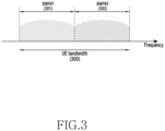
- FIG. 3 illustrates an example of a bandwidth part configuration in a wireless communication system according to an embodiment of the disclosure.
- FIG. 3 illustrates an example in which a UE bandwidth 300 is configured to include two bandwidth parts, that is, bandwidth part #1 (BWP#1) 301 and bandwidth part #2 (BWP#2) 302.
- a base station may configure one or multiple bandwidth parts for a UE, and may configure the following pieces of information with regard to each bandwidth part as given in Table 2 below.
- the bandwidth part configuration is not limited to the above example, and in addition to the configuration information in Table 2, various parameters related to the bandwidth part may be configured for the UE.
- the base station may transfer the configuration information to the UE through upper layer signaling, for example, radio resource control (RRC) signaling.
- RRC radio resource control
- One configured bandwidth part or at least one bandwidth part among multiple configured bandwidth parts may be activated. Whether or not the configured bandwidth part is activated may be transferred from the base station to the UE semi-statically through RRC signaling, or dynamically through downlink control information (DCI).
- DCI downlink control information
- an initial bandwidth part (BWP) for initial access may be configured for the UE by the base station through a master information block (MIB).
- the UE may receive configuration information regarding a control resource set (CORESET) and a search space which may be used to transmit a PDCCH for receiving system information (which may correspond to remaining system information (RMSI) or system information block 1 (SIB1) necessary for initial access through the MIB in the initial access step.
- system information which may correspond to remaining system information (RMSI) or system information block 1 (SIB1) necessary for initial access through the MIB in the initial access step.
- Each of the control resource set and the search space configured through the MIB may be considered (or identified) identity (ID) 0.
- the base station may notify the UE of configuration information, such as frequency allocation information, time allocation information, and numerology, regarding CORESET #0 through the MIB.
- the base station may notify the UE of configuration information regarding the monitoring cycle and occasion with regard to control resource set #0, that is, configuration information regarding search space #0, through the MIB.
- the UE may consider that a frequency domain configured by control resource set #0 acquired from the MIB is an initial bandwidth part for initial access.
- the ID of the initial bandwidth part may be considered (or identified) to be 0.
- the bandwidth part-related configuration supported by 5G may be used for various purposes.
- the base station may configure the frequency location (configuration information 2) of the bandwidth part for the UE, so that the UE can transmit/receive data at a specific frequency location within the system bandwidth.
- the base station may configure multiple bandwidth parts for the UE for the purpose of supporting different numerologies. For example, in order to support a UE's data transmission/reception using both a subcarrier spacing of 15kHz and a subcarrier spacing of 30kHz, two bandwidth parts may be configured as subcarrier spacings of 15kHz and 30kHz, respectively. Different bandwidth parts may be subjected to frequency division multiplexing (FDM), and in case that data is to be transmitted/received at a specific subcarrier spacing, the bandwidth part configured as the corresponding subcarrier spacing may be activated.
- FDM frequency division multiplexing
- the base station may configure bandwidth parts having different sizes of bandwidths for the UE for the purpose of reducing power consumed by the UE. For example, if the UE supports a substantially large bandwidth, for example, 100MHz, and always transmits/receives data with the corresponding bandwidth, a substantially large amount of power consumption may occur. Particularly, it may be substantially inefficient from the viewpoint of power consumption to unnecessarily monitor the downlink control channel with a large bandwidth of 100MHz in the absence of traffic.
- the base station may configure a bandwidth part of a relatively small bandwidth (for example, a bandwidth part of 20MHz) for the UE. The UE may perform a monitoring operation in the 20MHz bandwidth part in the absence of traffic, and may transmit/receive data with the 100MHz bandwidth part as instructed by the base station if data has occurred.
- UEs before being RRC-connected, may receive configuration information regarding the initial bandwidth part through an MIB in the initial access step.
- a UE may have a control resource set (CORESET) configured for a downlink control channel which may be used to transmit downlink control information (DCI) for scheduling a system information block (SIB) from the MIB of a physical broadcast channel (PBCH).
- DCI downlink control information
- SIB system information block
- PBCH physical broadcast channel
- the bandwidth of the control resource set configured by the MIB may be considered the initial bandwidth part, and the UE may receive, through the configured initial bandwidth part, a physical downlink shared channel (PDSCH) through which an SIB is transmitted.
- the initial bandwidth part may be used not only for the purpose of receiving the SIB, but also for other system information (OSI), paging, random access, or the like.
- OSI system information
- the base station may indicate, to the UE, to change (or switch or transition) the bandwidth parts by using a bandwidth part indicator field inside DCI.
- a bandwidth part indicator field inside DCI For example, if the currently activated bandwidth part of the UE is bandwidth part #1 301 in FIG. 3 , the base station may indicate bandwidth part #2 302 with a bandwidth part indicator inside DCI, and the UE may change the bandwidth part to bandwidth part #2 302 indicated by the bandwidth part indicator inside received DCI.
- DCI-based bandwidth part changing may be indicated by DCI for scheduling a PDSCH or a PUSCH, and thus, upon receiving a bandwidth part change request, the UE needs to be able to receive or transmit the PDSCH or PUSCH scheduled by the corresponding DCI in the changed bandwidth part with no problem.
- requirements for the delay time (T BWP ) required during a bandwidth part change are specified in standards, and may be defined given in Table 3 below, for example. However, Table 3 is merely an example, and the delay time required during a bandwidth part change is not limited thereto.
- the requirements for the bandwidth part change delay time may support type 1 or type 2, depending on the capability of the UE.
- the UE may report the supportable bandwidth part change delay time type to the base station.
- the UE may complete a change to the new bandwidth part indicated by the bandwidth part change indicator at a timepoint not later than slot n+TBWP, and may transmit/receive a data channel scheduled by the corresponding DCI in the newly changed bandwidth part.
- the base station may determine time domain resource allocation regarding the data channel, based on the UE's bandwidth part change delay time (TBWP).
- the base station may schedule the corresponding data channel after the bandwidth part change delay time, in connection with the method for determining time domain resource allocation regarding the data channel. Accordingly, the UE may not expect that the DCI that indicates a bandwidth part change will indicate a slot offset (K0 or K2) value smaller than the bandwidth part change delay time (T BWP ).
- the UE may perform no transmission or reception during a time interval from the third symbol of the slot used to receive a PDCCH including the corresponding DCI to the start point of the slot indicated by a slot offset (K0 or K2) value indicated by a time domain resource allocation indicator field in the corresponding DCI. For example, if the UE has received DCI indicating a bandwidth part change in slot n, and if the slot offset value indicated by the corresponding DCI is K, the UE may perform no transmission or reception from the third symbol of slot n to the symbol before slot n+K (for example, the last symbol of slot n+K-1).
- DCI for example, DCI format 1_1 or 0_1
- K2 slot offset
- An SS/PBCH block may refer to a physical layer channel block including a primary synchronization signal (PSS), a secondary synchronization signal (SSS), and a PBCH. Details thereof are as follows.
- PSS primary synchronization signal
- SSS secondary synchronization signal
- PBCH PBCH
- the UE may detect the PSS and the SSS in the initial access stage, and may decode the PBCH.
- the UE may acquire an MIB from the PBCH, and this may be used to configure control resource set (CORESET) #0 (which may correspond to a control resource set having a control resource set index of 0).
- CORESET control resource set
- the UE may monitor control resource set #0 by assuming that the demodulation reference signal (DMRS) transmitted in the selected SS/PBCH block and control resource set #0 are quasi-co-located (QCL).
- DMRS demodulation reference signal
- the UE may receive system information with downlink control information transmitted in control resource set #0.
- the UE may acquire configuration information related to a random access channel (RACH) necessary for initial access from the received system information.
- RACH random access channel
- the UE may transmit a physical RACH (PRACH) to the base station in consideration of a selected SS/PBCH index, and the base station, upon receiving the PRACH, may acquire information regarding the SS/PBCH block index selected by the UE.
- the base station may know which block the UE has selected from respective SS/PBCH blocks, and the fact that control resource set #0 associated therewith is monitored.
- PRACH physical RACH
- DCI downlink control information
- scheduling information regarding uplink data (or physical uplink shared channel (PUSCH)) or downlink data (or physical downlink shared channel (PDSCH)) is included in DCI and transferred from a base station to a UE through the DCI.
- the UE may monitor, with regard to the PUSCH or PDSCH, a fallback DCI format and a non-fallback DCI format.
- the fallback DCI format may include a fixed field predefined between the base station and the UE, and the non-fallback DCI format may include a configurable field.
- the DCI may be subjected to channel coding and modulation processes and then transmitted through a physical downlink control channel (PDCCH) after a channel coding and modulation process.
- a cyclic redundancy check (CRC) may be attached to the payload of a DCI message, and the CRC may be scrambled by a radio network temporary identifier (RNTI) corresponding to the identity of the UE.
- RNTI radio network temporary identifier
- Different RNTIs may be used according to the purpose of the DCI message, for example, UE-specific data transmission, power control command, or random access response. That is, the RNTI may not be explicitly transmitted, but may be transmitted while being included in a CRC calculation process.
- the UE may identify the CRC by using the allocated RNTI, and if the CRC identification result is right, the UE may know that the corresponding message has been transmitted to the UE.
- DCI for scheduling a PDSCH regarding system information (SI) may be scrambled by an SI-RNTI.
- DCI for scheduling a PDSCH regarding a random access response (RAR) message may be scrambled by an RA-RNTI.
- DCI for scheduling a PDSCH regarding a paging message may be scrambled by a P-RNTI.
- DCI for notifying of a slot format indicator (SFI) may be scrambled by an SFI-RNTI.
- DCI for notifying of transmit power control (TPC) may be scrambled by a TPC-RNTI.
- DCI for scheduling a UE-specific PDSCH or PUSCH may be scrambled by a cell RNTI (C-RNTI).
- C-RNTI cell RNTI
- DCI format 0_0 may be used as fallback DCI for scheduling a PUSCH, and in this case, the CRC may be scrambled by a C-RNTI.
- DCI format 0_0 in which the CRC is scrambled by a C-RNTI may include the following pieces of information given in Table 4 below, for example. [Table 4] - Identifier for DCI formats - [1] bit - Frequency domain resource assignment - log 2 N RB UL , BWP N RB UL , BWP + 1 / 2 bits - Time domain resource assignment - X bits - Frequency hopping flag - 1 bit.
- DCI format 0_1 may be used as non-fallback DCI for scheduling a PUSCH, and in this case, the CRC may be scrambled by a C-RNTI.
- DCI format 0_1 in which the CRC is scrambled by a C-RNTI may include the following pieces of information given in Table 5 below, for example.
- - Modulation and coding scheme - 5 bits - New data indicator - 1 bit - Redundancy version - 2 bits - HARQ process number - 4 bits - 1st downlink assignment index- 1 or 2 bits • 1 bit for semi-static HARQ-ACK codebook; • 2 bits for dynamic HARQ-ACK codebook with single HARQ-ACK codebook.
- Precoding information and number of layers - up to 6 bits - Antenna ports - up to 5 bits - SRS request - 2 bits - Channel state information (CSI) request - 0, 1, 2, 3, 4, 5, or 6 bits - Code block group (CBG) transmission information - 0, 2, 4, 6, or 8 bits - Phase tracking reference signal (PTRS)-demodulation reference signal (DDMRS) association - 0 or 2 bits.
- CSI Channel state information
- CBG Code block group
- PTRS Phase tracking reference signal
- DDMRS demodulation reference signal
- DCI format 1_0 may be used as fallback DCI for scheduling a PDSCH, and in this case, the CRC may be scrambled by a C-RNTI.
- DCI format 1_0 in which the CRC is scrambled by a C-RNTI may include the following pieces of information given in Table 6 below, for example. [Table 6] - Identifier for DCI formats - [1] bit - Frequency domain resource assignment - log 2 N RB DL , BWP N RB DL , BWP + 1 / 2 bits - Time domain resource assignment - X bits - VRB-to-PRB mapping - 1 bit.
- DCI format 1_1 may be used as non-fallback DCI for scheduling a PDSCH, and in this case, the CRC may be scrambled by a C-RNTI.
- DCI format 1_1 in which the CRC is scrambled by a C-RNTI may include the following pieces of information given in Table 7 below, for example.
- ZP Zero power
- CSI channel state information
- RS reference signal
- transport block 2 - Modulation and coding scheme - 5 bits - New data indicator - 1 bit - Redundancy version - 2 bits - HARQ process number - 4 bits - Downlink assignment index - 0 or 2 or 4 bits - TPC command for scheduled PUCCH - 2 bits - PUCCH resource indicator - 3 bits - PDSCH-to-HARQ_feedback timing indicator - 3 bits - Antenna ports - 4, 5 or 6 bits - Transmission configuration indication - 0 or 3 bits - SRS request -
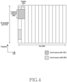
- FIG. 4 illustrates an example of a control resource set (CORESET) used to transmit a downlink control channel in a 5G wireless communication system.
- CORESET control resource set
- FIG. 4 illustrates an example in which a UE bandwidth part 410 is configured along the frequency axis, and two control resource sets (control resource set #1 420 and control resource set #2 401) are configured within one slot 402 along the time axis.
- the control resource sets 401 and 402 may be configured in a specific frequency resource 410 within the entire UE bandwidth part 403 along the frequency axis.
- the control resource sets may be each configured as one or multiple OFDM symbols along the time domain, and the number of the OFDM symbols may be defined as a control resource set duration 404. Referring to the example illustrated in FIG. 4 , control resource set #1 401 is configured to have a control resource set duration corresponding to two symbols, and control resource set #2 402 is configured to have a control resource set duration corresponding to one symbol.
- a control resource set in 5G described above may be configured for a UE by a base station through upper layer signaling (for example, system information, master information block (MIB), radio resource control (RRC) signaling).
- the description that a control resource set is configured for a UE may mean that information such as a control resource set identity, the control resource set's frequency location, and the control resource set's symbol duration is provided.
- the provided information may include the following pieces of information: given in Table 8 below.
- tci-StatesPDCCH (simply referred to as transmission configuration indication (TCI) state) configuration information may include information of one or multiple SS/PBCH block indexes or channel state information reference signal (CSI-RS) indexes, which are quasi-co-located (OCLed) with a DMRS transmitted in a corresponding CORESET.
- TCI transmission configuration indication
- CSI-RS channel state information reference signal
- FIG. 5 illustrates an example of a basic unit of time and frequency resources constituting a downlink control channel available in 5G.
- the basic unit of time and frequency resources constituting a control channel may be referred to as a resource element group (REG) 503, and the REG 503 may be defined by one OFDM symbol 501 along the time axis and one physical resource block (PRB) 502, that is, 12 subcarriers, along the frequency axis.
- the base station may configure a downlink control channel allocation unit by concatenating the REGs 503.
- one CCE 504 may include multiple REGs 503.
- the REG 503 may include 12 REs, and if one CCE 504 includes six REGs 503, one CCE 504 may then include 72 REs.
- a downlink control resource set once configured, may include multiple CCEs 504, and a specific downlink control channel may be mapped to one or multiple CCEs 504 and then transmitted according to the aggregation level (AL) in the control resource set.
- the CCEs 504 in the control resource set are distinguished by numbers, and the numbers of CCEs 504 may be allocated according to a logical mapping scheme.
- the basic unit of the downlink control channel illustrated in FIG. 5 may include both REs to which DCI is mapped, and an area to which a reference signal (DMRS 505) for decoding the same is mapped.
- DMRS 505 reference signal
- three DRMSs 503 may be transmitted inside one REG 505.
- the UE needs to detect a signal while being no information regarding the downlink control channel, and thus a search space indicating a set of CCEs may be defined for blind decoding.
- the search space may be a set of downlink control channel candidates including CCEs that the UE must attempt to decode in a given aggregation level. Since there are various aggregation levels making one bundle of 1, 2, 4, 8, or 16 CCEs, the UE may have a plurality of search spaces.
- a search space set may be defined as a set of search spaces at all configured aggregation levels.
- Search spaces may be classified into common search spaces and UE-specific search spaces.
- a group of UEs or all UEs may search a common search space of the PDCCH in order to receive cell-common control information such as dynamic scheduling regarding system information or a paging message.
- cell-common control information such as dynamic scheduling regarding system information or a paging message.
- PDSCH scheduling allocation information for transmitting an SIB including a cell operator information or the like may be received by searching the common search space of the PDCCH.
- a common search space a group of UEs or all UEs need to receive the PDCCH, and the common search space may thus be defined as a predetermined set of CCEs.
- Scheduling allocation information regarding a UE-specific PDSCH or PUSCH may be received by searching the UE-specific search space of the PDCCH.
- the UE-specific search space may be defined UE-specifically as a function of various system parameters and the identity of the UE.
- parameters for a search space regarding a PDCCH may be configured for the UE by the base station through upper layer signaling (for example, SIB, MIB, or RRC signaling).
- the base station may configure, for the UE, the number of PDCCH candidates at each aggregation level L, the monitoring cycle regarding the search space, the monitoring occasion with regard to each symbol in a slot regarding the search space, the search space type (common search space or UE-specific search space), a combination of an RNTI and a DCI format to be monitored in the corresponding search space, and/or a control resource set index for monitoring the search space, etc.
- parameters of the search space for the PDCCH may include the following pieces of information given in Table 9 below. However, this is merely an example, and the parameters of the search space may exclude some of the pieces of information in Table 9 or may further include other pieces of information in addition to the pieces of information in Table 9.
- the base station may configure one or multiple search space sets for the UE.
- the base station may configure search space set 1 and search space set 2 for the UE, may configure DCI format A scrambled by an X-RNTI to be monitored in a common search space in search space set 1.
- the base station may configure DCI format B scrambled by a Y-RNTI to be monitored in a UE-specific search space in search space set 2.
- one or multiple search space sets may exist in a common search space or a UE-specific search space.
- search space set #1 and search space set #2 may be configured as a common search space
- search space set #3 and search space set #4 may be configured as a UE-specific search space.
- Combinations of DCI formats and RNTIs given below may be monitored in a common search space.
- the combinations of DCI formats and RNTIs monitored in a common search space are not limited to the examples given below.
- Combinations of DCI formats and RNTIs given below may be monitored in a UE-specific search space.
- the combinations of DCI formats and RNTIs monitored in a UE-specific search space are not limited to the examples given below.
- Enumerated RNTIs may follow the definition and usage given below.
- DCI formats enumerated above may follow the definitions given in Table 10 below, for example.
- Table 10 DCI format Usage 0_0 Scheduling of PUSCH in one cell 0_1 Scheduling of PUSCH in one cell 1_0 Scheduling of PDSCH in one cell 1_1 Scheduling of PDSCH in one cell 2_0 Notifying a group of UEs of the slot format 2_1 Notifying a group of UEs of the PRB(s) and OFDM s ymbol(s) where UE may assume no transmission is inte nded for the UE 2_2 Transmission of TPC commands for PUCCH and PUSC H 2_3 Transmission of a group of TPC commands for SRS tr ansmissions by one or more UEs
- the search space at aggregation level L in connection with CORESET p and search space set s may be expressed by Equation 1 below.
- the Y p , n s , f ⁇ value may correspond to 0 in the case of a common search space.
- the Y p , n s , f ⁇ value may correspond to a value changed by the UE's identity (C-RNTI or ID configured for the UE by the base station) and the time index in the case of a UE-specific search space.
- multiple search space sets may be configured by different parameters (for example, parameters in Table 9), and the group of search space sets monitored by the UE at each timepoint may differ accordingly. For example, if search space set #1 is configured at by X-slot cycle, if search space set #2 is configured at by Y-slot cycle, and if X and Y are different, the UE may monitor search space set #1 and search space set #2 both in a specific slot, and may monitor one of search space set #1 and search space set #2 both in another specific slot.
- parameters in Table 9 parameters
- FIG. 7 illustrates an example of frequency domain resource allocation with regard to a physical downlink shared channel (PDSCH) or physical uplink shared channel (PUSCH) in a wireless communication system according to an embodiment of the disclosure.
- PDSCH physical downlink shared channel
- PUSCH physical uplink shared channel
- FIG. 7 illustrates three frequency domain resource allocation methods of type-0 700, type-1 705, and dynamic switch 710 which can be configured through an upper layer in an NR wireless communication system.
- partial downlink control information (DCI) for allocating a PDSCH to the UE include a bitmap including N RBG bits.
- N RBG refers to the number of resource block groups (RBGs) determined according to the BWP size allocated by a BWP indicator and upper layer parameter rbg-Size, as in Table 11 below, and data is transmitted in RBGs indicated as "1" by the bitmap.
- RBGs resource block groups
- the BWP size refers to the number of RBs included in the BWP.
- the other RBGs may each include P RBs.
- P may refer to the number of nominal RBGs as determined according to Table 11.
- some DCI for allocating PDSCHs to the UE may include frequency domain resource allocation information including bits.
- N RB BWP may denote the number of RBs included in a BWP.
- the base station may thereby configure a starting virtual resource block (starting VRB) 720 and the length 725 of a frequency domain resource allocated continuously therefrom.
- partial DCI for allocating a PDSCH to the corresponding UE includes frequency domain resource allocation information including as many bits as the larger value 735 between the payload 715 for configuring resource allocation type-0 and the payload 720 and 725 for configuring resource allocation type-1.
- MSB foremost part
- a base station may configure a table for time domain resource allocation information regarding a physical downlink shared channel (PDSCH) and a physical uplink shared channel (PUSCH) for a UE through upper layer signaling (for example, RRC signaling).
- PDSCH physical downlink shared channel
- PUSCH physical uplink shared channel
- the time domain resource allocation information may include PDCCH-to-PDSCH slot timing (for example, corresponding to a slot-unit time interval between a timepoint at which a PDCCH is received and a timepoint at which a PDSCH scheduled by the received PDCCH is transmitted; labeled K0), PDCCH-to-PUSCH slot timing (for example, corresponding to a slot-unit time interval between a timepoint at which a PDCCH is received and a timepoint at which a PUSCH scheduled by the received PDCCH is transmitted; hereinafter, labeled K2), information regarding the location and length of the start symbol by which a PDSCH or PUSCH is scheduled inside a slot, the mapping type of a PDSCH or PUSCH, and the like. For example, information such as in Table 12 or Table 13 below may be transmitted from the base station to the UE.
- the base station may notify the UF of one of the entries of the table regarding time domain resource allocation information described above through L1 signaling (for example, DCI) (for example, "time domain resource allocation" field in DCI may indicate the same).
- the UE may acquire time domain resource allocation information regarding a PDSCH or PUSCH, based on the DCI acquired from the base station.
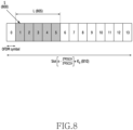
- FIG. 8 illustrates an example of time domain resource allocation with regard to a PDSCH in a wireless communication system according to an embodiment of the disclosure.
- the base station may indicate the time domain location of a PDSCH resource according to the subcarrier spacing (SCS) ( ⁇ PDSCH , ⁇ PDCCH ) of a data channel and a control channel configured by using an upper layer, the scheduling offset (K0) value, and the OFDM symbol start location 800 and length 805 within one slot dynamically indicated through DCI.
- SCS subcarrier spacing
- K0 scheduling offset
- FIG. 9 illustrates an example of time domain resource allocation according to a subcarrier spacing with regard to a data channel and a control channel in a wireless communication system according to an embodiment of the disclosure.
- the base station and the UE may accordingly generate a scheduling offset in conformity with a predetermined slot offset K0.
- the base station and the UE may accordingly generate a scheduling offset in conformity with a predetermined slot offset K0 with reference to the subcarrier spacing of the PDCCH.
- PUSCH transmission scheduling scheme will be described.
- PUSCH transmission may be dynamically scheduled by a UL grant inside DCI, or operated by means of configured grant Type 1 or Type 2.
- Dynamic scheduling indication regarding PUSCH transmission may be made by DCI format 0_0 or 0_1.
- Configured grant Type 1 PUSCH transmission may be configured semi-statically by receiving configuredGrantConfig including rrc-ConfiguredUplinkGrant in Table 14 through upper signaling, without receiving a UL grant inside DCI.
- Configured grant Type 2 PUSCH transmission may be scheduled semi-persistently by a UL grant inside DCI after receiving configuredGrantConfig not including rrc-ConfiguredUplinkGrant in Table 14 through upper signaling.
- PUSCH transmission is operated by a configured grant
- parameters applied to the PUSCH transmission are applied through configuredGrantConfig (upper signaling) in Table 14 except for dataScramblingIdentityPUSCH, txConfig, codebookSubset, maxRank, and scaling of UCI-OnPUSCH, which are provided by pusch-Config (upper signaling) in Table 15.
- pusch-Config upper signaling
- the UE applies tp-pi2BPSK inside pusch-Config in Table 15 to PUSCH transmission operated by a configured grant.
- the DMRS antenna port for PUSCH transmission may be substantially identical to an antenna port for SRS transmission.
- PUSCH transmission may follow a codebook-based transmission method and a non-codebook-based transmission method according to whether the value of txConfig inside pusch-Config in Table 15, which is upper signaling, is "codebook” or "nonCodebook”.
- PUSCH transmission may be dynamically scheduled through DCI format 0_0 or 0_1, and may be semi-statically configured by a configured grant.
- the UE may perform beam configuration for PUSCH transmission by using pucch-spatialRelationInfoID corresponding to a UE-specific PUCCH resource corresponding to the minimum ID inside an activated uplink BWP inside a serving cell, and the PUSCH transmission may be based on a single antenna port.
- the UE may not expect scheduling regarding PUSCH transmission through DCI format 0_0 inside a BWP having no configured PUCCH resource including pucch-spatialRelationInfo. If the UE has no configured txConfig inside pusch-Config in Table 17, the UE may not expect scheduling through DCI format 0_1.
- the codebook-based PUSCH transmission may be dynamically scheduled through DCI format 0_0 or 0_1, and may be semi-statically operated by a configured grant. If a codebook-based PUSCH is dynamically scheduled through DCI format 0_1 or configured semi-statically by a configured grant, the UE determines a precoder for PUSCH transmission, based on an SRS resource indicator (SRI), a transmission precoding matrix indicator (TPMI), and a transmission rank (the number of PUSCH transmission layers).
- SRI SRS resource indicator
- TPMI transmission precoding matrix indicator
- a transmission rank the number of PUSCH transmission layers.
- the SRI may be given through the SRS resource indicator (a field inside DCI) or configured through srs-ResourceIndicator (upper signaling).
- the UE has at least one SRS resource configured therefor, and may have a maximum of two SRS resources configured therefor.
- the SRS resource indicated by the corresponding SRI may refer to the SRS resource corresponding to the SRI, among SRS resources transmitted prior to the PDCCH including the corresponding SRI.
- the TPMI and the transmission rank may be given through "precoding information and number of layers" (a field inside DCI) or configured through precodingAndNumberOfLayers (upper signaling).
- the TPMI may be used to indicate a precoder to be applied to PUSCH transmission. If one SRS resource is configured for the UE, the TPMI may be used to indicate a precoder to be applied in the configured one SRS resource. If multiple SRS resources are configured for the UE, the TPMI is used to indicate a precoder to be applied in an SRS resource indicated through the SRI.
- the precoder to be used for PUSCH transmission may be selected from an uplink codebook having the same number of antenna ports as the value of nrofSRS-Ports inside SRS-Config (upper signaling).
- the UE may determine a codebook subset, based on codebookSubset inside pusch-Config (upper signaling) and TPMI.
- the codebookSubset inside pusch-Config (upper signaling) may be configured to be one of "fullyAndPartialAndNonCoherent", "partialAndNonCoherent", or "noncoherent", based on UE capability reported by the UE to the base station.
- codebookSubset (upper signaling) will be configured as "fullyAndPartialAndNonCoherent”.
- UE may not expect that the value of codebookSubset (upper signaling) will be configured as "fullyAndPartialAndNonCoherent” or "partialAndNonCoherent”.
- nrofSRS-Ports inside SRS-ResourceSet indicates two SRS antenna ports, the UE does not expect that the value of codebookSubset (upper signaling) will be configured as "partialAndNonCoherent”.
- the UE may have one SRS resource set configured therefor, wherein the value of usage inside SRS-ResourceSet (upper signaling) is "codebook", and one SRS resource may be indicated through an SRI inside the corresponding SRS resource set. If multiple SRS resources are configured inside the SRS resource set wherein the value of usage inside SRS-ResourceSet (upper signaling) is "codebook", the UE expects that the value of nrofSRS-Ports inside SRS-Resource (upper signaling) is identical for all SRS resources.
- the UE may transmit, to the base station, one or multiple SRS resources included in the SRS resource set wherein the value of usage is configured as "codebook" according to upper signaling.
- the base station may select one from the SRS resources transmitted by the UE and indicate the UE to be able to transmit a PUSCH by using transmission beam information of the corresponding SRS resource.
- the SRI is used as information for selecting the index of one SRS resource, and is included in DCI.
- the base station may add information indicating the rank and TPMI to be used by the UE for PUSCH transmission to the DCI.
- the UE may apply, in performing PUSCH transmission, the precoder indicated by the rank and TPMI indicated based on the transmission beam of the corresponding SRS resource, thereby performing PUSCH transmission.
- non-codebook-based PUSCH transmission may be dynamically scheduled through DCI format 0_0 or 0_1, and may be semi-statically operated by a configured grant. If at least one SRS resource is configured inside an SRS resource set wherein the value of usage inside SRS-ResourceSet (upper signaling) is "nonCodebook", non-codebook-based PUSCH transmission may be scheduled for the UE through DCI format 0_1.
- one connected NZP CSI-RS resource may be configured for the UE.
- the UE may calculate a precoder for SRS transmission by measuring the NZP CSI-RS resource connected to the SRS resource set. If the difference between the last received symbol of an aperiodic NZP CSI-RS resource connected to the SRS resource set and the first symbol of aperiodic SRS transmission in the UE is less than 42 symbols, the UE does not expect that information regarding the precoder for SRS transmission will be updated.
- the connected NZP CSI-RS may be indicated by an SRS request which is a field inside DCI format 0_1 or 1_1. If the connected NZP CSI-RS resource is an aperiodic NZP CSI-RS resource, the existence of the connected NZP CSI-RS may be indicated with regard to the case in which the value of SRS request (a field inside DCI format 0_1 or 1_1) is not "00". The corresponding DCI should not indicate cross carrier or cross BWP scheduling.
- the NZP CSI-RS may be located in the slot used to transmit the PDCCH including the SRS request field.
- TCI states configured for the scheduled subcarrier may not be configured as QCL-TypeD.
- the connected NZP CSI-RS may be indicated through associatedCSI-RS inside SRS-ResourceSet (upper signaling).
- the UE may not expect that spatialRelationInfo which is upper signaling regarding the SRS resource and associatedCSI-RS inside SRS-ResourceSet (upper signaling) will be configured together.
- the UE may determine a precoder to be applied to PUSCH transmission and the transmission rank, based on an SRI indicated by the base station.
- the SRI may be indicated through the SRS resource indicator (a field inside DCI) or configured through srs-ResourceIndicator (upper signaling).
- the SRS resource indicated by the corresponding SRI refers to the SRS resource corresponding to the SRI, among SRS resources transmitted prior to the PDCCH including the corresponding SRI.
- the UE may use one or multiple SRS resources for SRS transmission.
- the UE may use one or multiple SRS resources for SRS transmission, and the maximum number of SRS resources that can be transmitted simultaneously in the same symbol inside one SRS resource set and the maximum number of SRS resources are determined by UE capability reported to the base station by the UE.
- SRS resources simultaneously transmitted by the UE may occupy the same RB.
- the UE may configure one SRS port for each SRS resource. There may be only one configured SRS resource set wherein the value of usage inside SRS-ResourceSet (upper signaling) is "nonCodebook", and a maximum of four SRS resources may be configured for non-codebook-based PUSCH transmission.
- the base station may transmit one NZP-CSI-RS connected to the SRS resource set to the UE.
- the UE may calculate the precoder to be used when transmitting one or multiple SRS resources inside the corresponding SRS resource set, based on the result of measurement when the corresponding NZP-CSI-RS is received.
- the UE may apply the calculated precoder when transmitting, to the base station, one or multiple SRS resources inside the SRS resource set wherein the usage is configured as "nonCodebook".
- the base station may select one or multiple SRS resources from the received one or multiple SRS resources.
- the SRI may indicate an index that may express one SRS resource or a combination of multiple SRS resources.
- the number of SRS resources indicated by the SRI transmitted by the base station may be the number of transmission layers of the PUSCH, and the UE may transmit the PUSCH by applying the precoder applied to SRS resource transmission to each layer.
- FIG. 10 illustrates radio protocol structures of a base station and a UE in single cell, carrier aggregation, and dual connectivity situations according to an embodiment of the disclosure.
- a radio protocol of a wireless communication system may be configured by an NR service data adaptation protocol (SDAP) S25 or S70, an NR packet data convergence protocol (PDCP) S30 or S65, an NR radio link control (RLC) S35 or S60, and an NR medium access controls (MAC) S40 or S55 on each of UE and NR base station sides.
- SDAP NR service data adaptation protocol
- PDCP packet data convergence protocol
- RLC radio link control
- MAC medium access controls
- the radio protocol of the wireless communication system may include an NR SDAP S25 or S70, an NR PDCP S30 or S65, an NR RLC S35 or S60, and an NR MAC S40 or S55 on each of UE and NR base station sides.
- the main functions of the NR SDAP S25 or S70 may include at least some of functions below.
- whether to use the header of the SDAP layer device or whether to use functions of the SDAP layer device may be configured for the UE through an RRC message according to PDCP layer devices or according to bearers or according to logical channels.
- the non-access stratum (NAS) quality of service (QoS) reflection configuration 1-bit indicator (NAS reflective QoS) of the SDAP header and the access stratum (AS) QoS reflection configuration 1-bit indicator (AS reflective QoS) may indicate, to the UE, that the UE can update or reconfigure mapping information regarding the QoS flow and data bearer of the uplink and downlink.
- the SDAP header may include QoS flow ID information indicating the QoS.
- the QoS information may be used as data processing priority, scheduling information, etc. for smoothly supporting services.
- the main functions of the NR PDCP S30 or S65 may include at least some of functions below.
- the reordering of the NR PDCP device may refer to a function of reordering PDCP PDUs received from a lower layer in an order based on the PDCP sequence number (SN), and may include a function of transferring data to an upper layer in the reordered sequence.
- the reordering of the NR PDCP device may include a function of instantly transferring data without considering the order, may include a function of recording PDCP PDUs lost as a result of reordering, may include a function of reporting the state of the lost PDCP PDUs to the transmitting side, and may include a function of requesting retransmission of the lost PDCP PDUs.
- the main functions of the NR RLC S35 or S60 may include at least some of functions below.
- the in-sequence delivery of the NR RLC device may refer to a function of successively delivering RLC SDUs received from the lower layer to the upper layer.
- the in-sequence delivery of the NR RLC device may include a function of reassembling and delivering multiple RLC SDUs received, into which one original RLC SDU has been segmented, may include a function of reordering the received RLC PDUs with reference to the RLC sequence number (SN) or PDCP sequence number (SN), may include a function of recording RLC PDUs lost as a result of reordering, may include a function of reporting the state of the lost RLC PDUs to the transmitting side, and may include a function of requesting retransmission of the lost RLC PDUs.
- the in-sequence delivery of the NR RLC device may include a function of, if there is a lost RLC SDU, successively delivering only RLC SDUs before the lost RLC SDU to the upper layer, and may include a function of, if a predetermined timer has expired although there is a lost RLC SDU, successively delivering all RLC SDUs received before the timer was started to the upper layer.
- the in-sequence delivery of the NR RLC device may include a function of, if a predetermined timer has expired although there is a lost RLC SDU, successively delivering all currently received RLC SDUs to the upper layer.
- the in-sequence delivery of the NR RLC device may process RLC PDUs in the received order (regardless of the sequence number order, in the order of arrival) and deliver same to the PDCP device regardless of the order (out-of-sequence delivery). If receiving segments, the NR RLC device may receive segments stored in a buffer or to be received later, reconfigure the segments into one whole RLC PDU, process the RLC PDU, and then deliver the processed RLC PDU to the NR PDCP device.
- the NR RLC layer may include no concatenation function, which may be performed in the NR MAC layer or replaced with a multiplexing function of the NR MAC layer.
- the out-of-sequence delivery of the NR RLC device may refer to a function of instantly delivering RLC SDUs received from the lower layer to the upper layer regardless of the order.
- the out-of-sequence delivery of the NR RLC device may include a function of reassembling and delivering multiple RLC SDUs received, into which one original RLC SDU has been segmented, and may include a function of storing the RLC SN or PDCP SN of received RLC PDUs, and recording RLC PDUs lost as a result of reordering.
- the NR MAC S40 or S55 may be connected to multiple NR RLC layer devices configured in one UE, and the main functions of the NR MAC may include at least some of functions below.
- an NR PHY layer S45 or S50 may perform operations of channel-coding and modulating upper layer data, thereby obtaining OFDM symbols, and delivering the same through a radio channel, or demodulating OFDM symbols received through the radio channel, channel-decoding the same, and delivering the same to the upper layer.
- the detailed structure of the radio protocol structure may be variously changed according to the carrier (or cell) operating scheme.
- the base station and the UE may use a protocol structure having a single structure with regard to each layer, such as S00.
- the base station and the UE may use a protocol structure which has a single structure up to the RLC, but multiplexes the PHY layer through a MAC layer, such as S10.
- the base station and the UE may use a protocol structure which has a single structure up to the RLC, but multiplexes the PHY layer through a MAC layer, such as S20.
- DC dual connectivity
- PDCCH repetitive transmission is not supported in current Rel-15 and Rel-16 NR, and it may be thus difficult to achieve required reliability in a scenario requiring high reliability, such as URLLC.
- the disclosure may improve the PDCCH reception reliability of a UE by providing a PDCCH repetitive transmission method through multiple transmission points (TRPs). Specific methods thereof will be described hereinafter through the embodiments below.
- upper signaling is a method for transferring signals from a base station to a UE by using a downlink data channel of a physical layer, or from the UE to the base station by using an uplink data channel of the physical layer, and may also be referred to as "RRC signaling", “PDCP signaling”, or “medium access control (MAC) control element (MAC CE)".
- RRC signaling PDCP signaling
- MAC CE medium access control control element
- the UE may use various methods to determine whether or not to apply cooperative communication, for example, PDCCH(s) that allocates a PDSCH to which cooperative communication is applied have a specific format, or PDCCH(s) that allocates a PDSCH to which cooperative communication is applied include a specific indicator indicating whether or not to apply cooperative communication, or PDCCH(s) that allocates a PDSCH to which cooperative communication is applied are scrambled by a specific RNTI, or cooperative communication application is assumed in a specific range indicated by an upper layer.
- NC-JT case refers to a case in which the UE receives a PDSCH to which cooperative communication is applied, based on conditions similar to those described above.
- determining priority between A and B may be variously described as, for example, selecting an entity having a higher priority according to a predetermined priority rule and performing an operation corresponding thereto, or omitting or dropping operations regarding an entity having a lower priority.
- a base station is an entity that allocates resources to terminals, and may be at least one of a gNode B, an eNode B, a Node B, a base station (BS), a wireless access unit, a base station controller, and a node on a network.
- a terminal may include a user equipment (UE), a mobile station (MS), a cellular phone, a smartphone, a computer, or a multimedia system capable of performing a communication function.
- UE user equipment
- MS mobile station
- a cellular phone a smartphone
- computer or a multimedia system capable of performing a communication function.
- a 5G system will be described by way of example, but the embodiments of the disclosure may also be applied to other communication systems having similar technical backgrounds or channel types.
- Examples of such communication systems may include LTE or LTE-A mobile communication systems and mobile communication technologies developed beyond 5G. Therefore, based on determinations by those skilled in the art, the embodiments of the disclosure may also be applied to other communication systems through some modifications without significantly departing from the scope of the disclosure. The contents of the disclosure may be applied to FDD and TDD systems.
- upper layer signaling may refer to signaling corresponding to at least one signaling among the following signaling, or a combination of one or more thereof.
- L1 signaling may refer to signaling corresponding to at least one signaling method among signaling methods using the following physical layer channels or signaling, or a combination of one or more thereof.
- Scheduling DCI for example, DCI used for the purpose of scheduling downlink or uplink data
- determining priority between A and B may be variously described as, for example, selecting an entity having a higher priority according to a predetermined priority rule and performing an operation corresponding thereto, or omitting or dropping operations regarding an entity having a lower priority.
- the SBFD may be referred to as a technology wherein a part of a downlink resource is used as an uplink resource in a TDD spectrum of frequencies below 6GHz or frequencies above 6GHz such that uplink transmission is received from a UE as much as the increased uplink resource, thereby expanding the UE's uplink coverage, and feedback regarding downlink transmission is received from the UE in the expanded uplink resource, thereby reducing feedback delay.
- a UE which may receive information regarding whether SBFD is supported from the base station and may perform uplink transmission in a part of the downlink resource may be referred to as an SBFD-capable UE for convenience of description.
- the following scheme may be considered to define the SBFD in specifications and for the SBFD-capable UE to determine that SBFD is supported in a specific cell (for frequency/frequency band).
- the first scheme in order to define SBFD in addition to the frame structure type of the existing unpaired spectrum (or time division duplex (TDD)) or paired spectrum (or frequency division duplex (FDD)), another frame structure type (for example, frame structure type 2 may be introduced).
- Frame structure type 2 may be defined to be supported at a specific frequency or in a specific frequency band, or the base station may indicate, to the UE, whether SBFD is supported by using system information.
- the SBFD-capable UE may receive system information indicating whether SBFD is supported and may thus determine whether SBFD is supported in a specific cell (or frequency/frequency band).
- the second scheme may indicate whether SBFD is additionally supported at a specific frequency or in a specific frequency band of the existing unpaired spectrum (or TDD) without defining a new frame structure type.
- the second scheme may define whether SBFD is additionally supported at a specific frequency or in a specific frequency band of the existing unpaired spectrum, or the base station may indicate, to the UE, whether SBFD is supported by using system information.
- the SBFD-capable UE may receive system information indicating whether SBFD is supported and may thus determine whether SBFD is supported in a specific cell (or frequency/frequency band).
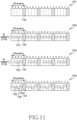
- the information regarding whether SBFD is supported may be information (for example, SBFD resource configuration information described later with reference to FIG. 11 ) indicating whether SBFD is supported indirectly by additionally configuring a part of a downlink resource as an uplink resource, in addition to the configuration regarding TDD uplink (UL) - downlink (DL) resource configuration information indicating the TDD's downlink slot (or symbol) resource and uplink slot (or symbol) resource.
- the information regarding whether SBFD is supported in the first and second schemes may directly indicate whether SBFD is supported.
- the SBFD-capable UE may receive a synchronization signal block during an initial cell access for accessing a cell (or base station), thereby acquiring cell synchronization.
- the process of acquiring cell synchronization may be identical for the SBFD-capable UE and the existing TDD UE. Thereafter, the SBFD-capable UE may determine whether the cell supports SBFD through an MIB acquisition or SIB acquisition or random access process.
- system information for transmitting information regarding whether SBFD is supported may be distinguished from system information for a UE (for example, existing TDD UE) supporting a different version of specifications in the cell and then transmitted separately therefrom.
- the SBFD-capable UE may acquire all or part of the system information transmitted separately from the system information for the existing TDD UE, thereby determining whether SBFD is supported.
- the cell or base station may determine that the UE supports TDD only.
- the information regarding whether SBFD is supported may be inserted in the last portion so as not to affect the existing TDD UE's system information acquisition.
- the SBFD-capable UE fails to acquire the information regarding whether SBFD is supported, inserted in the last portion, or acquires information indicating that SBFD is not supported, the cell (or base station) may determine that the UE supports TDD only.
- the information regarding whether SBFD is supported may be transmitted by using a separate PDSCH so as not to affect the existing TDD UE's system information acquisition. That is, a UE that does not support SBFD may receive a first SIB (or SIB1) including existing TDD-related system information through a first PDSCH. A UE that supports SBFD may receive a first SIB (or SIB1) including existing TDD-related system information through a first PDSCH, and may receive SBFD-related system information through a second PDSCH.
- the first PDSCH and the second PDSCH may be scheduled by a first PDCCH and a second PDCCH, and the cyclic redundancy code (CRC) of the first PDCCH and the second PDCCH may be scrambled by the same RNTI (for example, SI-RNTI).
- the search space for monitoring the second PDCCH may be acquired from the first PDCCH's system information, and if the same fails to be acquired (that is, if the first PDCCH's system information includes no information regarding the search space), the second PDCCH may be received in the same search space as the search space of the first PDCCH.
- the SBFD-capable UE may perform a random access procedure and data/control signal transmission and/or reception in the same manner as the existing TDD UE.
- the base station may configure a separate random access resource for each of existing TDD UEs or SBFD-capable UEs (for example, an SBFD-capable UE supporting duplex communication and an SBFD-capable UE supporting half-duplex communication).
- the base station may transmit configuration information regarding the random access resource (for example, configuration information or control information indicating a time-frequency resource that may be used for a PRACH) to an SBFD-capable UE through system information.
- the system information for transmitting information regarding the random access resource may be distinguished from system information for a UE (for example, existing TDD UE) supporting a different version of specifications in the cell and then transmitted separately therefrom.
- the base station may configure a separate random access resource with regard to a TDD UE supporting a different version of specifications and an SBFD-capable UE, thereby distinguishing whether the TDD UE supporting a different version of specifications performs a random access or the SBFD-capable UE performs a random access.
- a separate random access resource configured with regard to the SBFD-capable UE may be deemed to be a downlink time resource by the existing TDD UE.
- the base station may determine that the SBFD-capable UE has attempted a random access in the uplink resource.
- the base station may not configure a separate random access resource for the SBFD-capable UE, and may configure a common random access resource for all UEs in the cell.
- configuration information regarding the random access resource may be transmitted to all UEs in the cell through system information, and upon receiving the system information, the SBFD-capable UE may perform a random access by using the random access resource.
- the SBFD-capable UE may then complete the random access procedure and may proceed to an RRC connected mode for transmitting/receiving data with the cell.
- the SBFD-capable UE may receive an upper layer or physical signal, by which the same may determine that some frequency resources of downlink time resources are configured as uplink resources, from the base station, and may perform an SBFD operation, for example, transmit uplink signals in uplink resources.
- the SBFD-capable UE may transmit capability information including at least one from among information regarding whether the UE supports SBFD, information regarding whether full-duplex communication or half-duplex communication is supported, the number of transmission and/or receptions antennas which the same has (or supports), and the like to the base station, thereby informing the base station that the SBFD-capable UE is attempting an access.
- the capability information may not include information regarding whether half-duplex communication is supported.
- the SBFD-capable UE may report capability information to the base station through a random access process, may report the same to the base station after completing the random access process, or may report the same to the base station after completing proceeding to an RRC connected mode for transmitting/receiving data with the cell.
- the SBFD-capable UE may support half-duplex communication such that uplink transmission or downlink reception is solely performed at one moment, similarly to the existing TDD UE, or may support full-duplex communication such that both uplink transmission and downlink reception are performed at one moment. Therefore, the SBFD-capable UE may report whether the half-duplex communication or full-duplex communication is supported to the base station through capability reporting. After the reporting, the base station may configure the SBFD-capable UE regarding whether the SBFD-capable UE is supposed to perform transmission/reception by using half-duplex communication or full-duplex communication. In case that the SBFD-capable UE reports capability regarding half-duplex communication to the base station, a switching gap may be necessary to change the RF between transmission and reception in case of operating in FDD or TDD, because no duplexer generally exists.
- FIG. 11 illustrates an example in which SBFD is operated in a TDD spectrum of a wireless communication system to which the disclosure is applied.
- FIG. 11 illustrates an example in which TDD is operated in a specific frequency band in connection with a TDD only configuration 1151 according to an embodiment.
- a base station may transmit and/or receive a signal including data/control information with an existing TDD UE or with an SBFD-capable UE in a downlink slot (or symbol), uplink slot (or symbol) 1101, a flexible slot (or symbol), based on a configuration regarding TDD UL-DL resource configuration information indicating the TDD's downlink slot (or symbol) resource and uplink slot (or symbol) resource.
- a DDDSU slot format is configured according to the TDD UL-DL resource configuration information.
- D may refer to a slot entirely configured by downlink symbols.
- U may refer to a slot entirely configured by uplink symbols.
- S may refer to a slot which is neither "D” nor "U”, that is, a slot including downlink symbols or uplink symbols or including flexible symbols. It may be assumed in FIG. 11 of the disclosure that S is configured by 12 downlink symbols and 2 flexible symbols for convenience of description.
- the DDDSU slot format may be repeated according to the TDD UL-DL resource configuration information. That is, the repetition cycle of the TDD configuration may correspond to 5 slots (5ms in the case of 15kHz SCS, 2.5ms in the case of 30kHz SCS, or the like).
- FIG. 11 illustrates an example in which SBFD is operated together with TDD in a specific frequency band in connection with SBFD configuration 1 1152, SBFD configuration 2 1153, or SBFD configuration 3 1154.
- the base station may configure some bands among the cell's frequencies as a frequency band 1110 in which uplink transmission is possible, for the UE.
- the frequency band in which uplink transmission is possible may be referred to as a UL subband.
- the UL subband may be applied to all symbols of all slots.
- the UE may transmit scheduled uplink channels or signals by using all symbols 1112 in the UL subband. However, the UE cannot transmit uplink channels or signals in bands other than the UL subband.
- some bands among the cell's frequencies may be configured for the UE as a frequency band 1120 in which uplink transmission is possible, and a time domain in which the frequency band is activated may be configured for the UE.
- the frequency band in which uplink transmission is possible may be referred to as a UL subband.
- the UL subband is deactivated in the first slot, and the UL subband may be activated in remaining slots. Therefore, the UE may transmit uplink channels or signals in the UL subband 1122 of remaining slots. Therefore, the UL subband is activated with regard to each slot in FIG. 11 , but this is only an example, the activation of the UL subband may be configured with regard to each symbol.
- the base station may configure a time-frequency resource in which uplink transmission is possible, for the UE.
- One or more time-frequency resources may be configured for the UE as time-frequency resources in which uplink transmission is possible.
- some frequency bands 1132 of the first slot and the second slot may be configured as time-frequency resources in which uplink transmission is possible.
- some frequency bands 1133 of the third slot and some frequency bands 1134 of the fourth slot may be configured as time-frequency resources in which uplink transmission is possible.
- a time-frequency resource in which uplink transmission is possible in a downlink symbol or slot may be referred to as an SBFD resource.
- a symbol having a UL subband configured therefor in a downlink symbol may be referred to as an SBFD symbol.
- a time-frequency resource in which downlink transmission is possible in an uplink symbol or slot may be referred to as an SBFD resource.
- a symbol having a DL subband configured therefor in an uplink symbol may be referred to as an SBFD symbol.
- a band in which downlink channel or signal reception is possible may be referred to as a DL subband.
- a UE may configure a maximum of one UL subband in one symbol, and may configure a maximum of two DL subbands. For example, one of ⁇ UL subband, DL subband ⁇ , ⁇ DL subband, UL subband ⁇ , or ⁇ first DL subband, UL subband, second DL subband ⁇ may be configured for the UE in the frequency domain.
- one of the following three may be uses as the index of RBs in the frequency domain.
- the common RB index if starts from 0, may increase in proportion to the frequency.
- the UE may refer to the subcarrier matching with "point A" as subcarrier 0.
- every 12 subcarriers may be grouped and given the common RB index. That is, in case that the subcarrier index is k, the value corresponding to floor(k/12) is the common RB index of the RB to which the subcarrier belongs.
- the common RB index may be determined according to point A. Since point A is commonly configured for all UEs of the cell, all UEs may have the same common RB index.
- a downlink BWP for receiving channels or signals or an uplink BWP for transmitting the same may be configured for the UE.
- the UE may assume that, as a BWP-specific RB index, the index of the lowest RB of a BWP is 0.
- n CRB is the common RB index
- n PRB is the BWP-specific RB index.
- the UE may have a UL subband configured for a downlink symbol.
- a DL subband may be configured for an uplink symbol. It may be assumed in that, in connection with the subband-specific RB index, the index of the lowest RB among RBs included in a subband is 0.
- the position of the starting RB of a subband may be given as N CRB ⁇ sub start . That is, the base station may configure the value of N CRB ⁇ sub start for the UE through an upper layer signal.
- n CRB may be the common RB index, and n sub may be the subband-specific RB index.
- a subband having the starting RB's position configured by the value of N CRB ⁇ sub start may be applied to all BWPs of the UE. That is, the same may not be BWP-specific.
- the position of the starting RB of a subband may be given or indicated as N PRB ⁇ sub start . That is, the base station may configure the value of N PRB ⁇ sub start for the UE through an upper layer signal. The value may be configured for a specific BWP.
- n PRB may be the BWP-specific RB index, and n sub may be the subband-specific RB index.
- N CRB ⁇ sub start N BWP start + N PRB ⁇ sub start
- N PRB ⁇ sub start N CRB ⁇ sub start ⁇ N BWP start .
- type-0 resource allocation scheme is configured for a UE. It may be assumed that the number of RBs included in the UE's UL BWP is N RB ULBWP . It may also be assumed that the number of RBs included in a UL subband is N RB ULsub , and the index of the starting RB of the UL subband is N CRB ⁇ sub start . For convenience of description, it may be assumed in the disclosure that RBs included in a UL subband are all included in RBs that a UL BWP includes. However, in a specific configuration, not all RBs included in a UL subband may be included in RBs that a UL BWP includes.
- N RB ULsub may be the number of RBs included in both the UL BWP and the UL subband.
- N CRB ⁇ sub start may be the lowest index among RBs included in both the UL BWP and the subband. Therefore, N CRB ⁇ sub start may be the larger value between N CRB ⁇ sub start and N BWP start .
- N RB ULsub and N CRB ⁇ sub start may differ depending on the time domain. This is because different UL subbands may be configured depending on the time domain. However, it may be assumed in the disclosure that one UL subband is configured. That is, N RB ULsub and N CRB ⁇ sub start are identical in the time domain.
- N RB ULsub and N CRB ⁇ sub start may be as follows: in case that multiple, for example, two UL subbands (indexed as #1 and #2) are configured, N RB ULsub may be the value of one of N RB ULsub # 1 and N RB ULsub # 2 , and N CRB ⁇ sub start may be the value of one of N CRB ⁇ sub # 2 start and N CRB ⁇ sub # 2 start .
- FIG. 12 is illustrated to describe an embodiment of the disclosure.
- FIG. 12 illustrates an example only, and this embodiment is substantially equally applicable to other embodiments.
- an uplink symbol, a downlink symbol, or a flexible symbol may be configured for a UE according to a TDD configuration.
- all symbols of slot "D" may be downlink symbols.
- All symbols of slot “U” may be uplink symbols.
- Slot “S” may be a slot that is neither slot "D" nor slot "U”.
- a UL BWP 1220 may be configured for the UE.
- a UL subband 1210 may be configured in a DL symbol for the UE. It may be assumed in the disclosure that the UL BWP includes 275 RBs, and the UL subband includes 50 RBs.
- the i th bit (indexed in the order from the most significant bit to the least significant bit) may indicate whether the i th RGB has been scheduled.
- FIG. 13 illustrates an RBG configuration according to an embodiment of the disclosure.
- Remaining RBGs may include P RBs. For example, referring to FIG.
- each of the first 17 RBGs (RBG#0, RBG#1, ..., RBG#16 of the first index 1311 in FIG. 13 ) may include 16 RBs, and the last RBG (RBG#17 of the first index 1311 in FIG. 13 ) may include 3 RBGs.
- the UL subband may be smaller than or equal to the number of RBs of UL BWP. That is, N RB ULsub ⁇ N RB ULBWP . Therefore, if the UL subband (or the number of RBs of the UL subband) is smaller than the number of RBs of UL BWP, RBs included in some RBGs of the UL BWP may not be included in the UL subband. That is, although the DCI format received by the UE includes an FDRA field having N RBG bits, some bits among the same may not indicate scheduling information always. That is, some bits are included in the DCI format but are not used. Therefore, the DCI format includes unnecessary bits.
- Method 1 determines and indicates the UL subband's RBG based on the number of bits of the FDRA field
- the UE may determine the number of bits of the FDRA field according to the number of RBGs generated based on the UL BWP, and may group RBs of the UL subband into an RBG, based on the number of bits of the FDRA field.
- the RBG generated based on the UL BWP may be referred to as the first RBG
- the RBG into which RBs of the UL subband are grouped may be referred to as the second RBG.
- the second RBG may be determined as follows.
- the number of bits of the FDRA field determined according to the number of first RBGs may be referred to as B FDRA .
- B FDRA The number of bits of the FDRA field determined according to the number of first RBGs.
- the UL subband is configured by RBs, the number of which is N RB ULsub .
- the UE may cluster N RB ULsub RBs into as many groups as B FDRA . Therefore, the UE may cluster the same such that the number of second RBGs is B FDRA .
- the clustering method (or grouping method) may be at least one of the following:
- first RBGs as floor N RB ULsub / Q may each include as many RBs as Q. That is, the index of RBs included in the first RBG may be ⁇ 0,1,...,Q-1 ⁇ , the index of RBs included in the second RBG may be ⁇ Q,Q+1,...,2*Q-1 ⁇ , ... , and the index of RBs included in the floor N RB ULsub / Q th RBG may be floor N RB ULsub / Q ⁇ 1 * Q , ... , floor N RB ULsub / Q * Q ⁇ 1 .
- the index of RBs included in the floor N RB ULsub / Q + 1 th RBG RGB may be floor N RB ULsub / Q * Q , floor N RB ULsub / Q * Q + 1 , ... , N RB ULsub ⁇ 1 .
- the index may be the subband-specific RB index.
- the first floor N RB ULsub / Q 16 RBGs (RBG#0, RBG#1, ..., RBG#15 of the second index 1312 in FIG. 13 ) may each include 3 RBs.
- the i th bits of the FDRA field may indicate whether the i th second RGB is scheduled or not.
- the UE may cluster as many RBs as N RB ULsub into B FDRA groups as follows:
- the i th second RBG may include RBs, the subband-specific RB index of which is ⁇ (i-1)*K1, (i-1)*K1+1,..., i*K1-1 ⁇ .
- the i M1+1,..., B FDRA
- the i th second RBG may include RBs, the subband-specific RB index of which is ⁇ M1*K1+(i-M1-1)*K2, M1*K1+(i-M1-1)*K2+1,..., M1*K1+(i-M1)*K2-1 ⁇ .
- the i th bit of the FDRA field may indicate whether the second RBG is scheduled or not.
- the i th second RBG (RBG#0, RBG#1, ..., RBG#13 in the third index 1313 in FIG. 13 ) may include RBs, the subband-specific RB index of which is ⁇ (i-1)*3, (i-1)*3+1,..., i*3-1 ⁇ .
- B FDRA second RBGs may all be valid.
- ceil (x) may indicate the smallest integer among numbers larger than or equal to x
- floor (x) may indicate the largest integer among numbers smaller than or equal to x.
- Method 2 determines and indicates RBGs, based on the number of bits of the FDRA field and the frequency position of the UL subband
- the number of RBs included in the second RBG obtained in the previous method, or the nominal RBG size, may not be a power of two.
- the RBG boundary may not match between different UEs.
- the second method may be directed to solve the case in which the RBG boundary do not match between different UEs.
- the UE may select one of powers of two as the nominal RBG value of the second RBG.
- One value may be selected from powers of two: 1, 2, 4, 8, and 16.
- the nominal RBG value of the second RBG the number of bits of the FDRA field or the frequency position of the UL subband may be considered.
- an RB corresponding to common RB index N CRB ⁇ sub start may be given subband-specific RB index 0.
- RBs of the UL subband may be grouped into the second RBG, based on X.
- the index of RBs of the UL is the subband-specific RB index.
- Remaining second RBGs may include XRBs.
- the first second RBG (RBG#0 in the fourth index 1314 in FIG. 13 ) may include 2 RBs, and remaining 12 second RBGs (RBG#1, RBG#2, ..., RBG#12 in the fourth index 1314 in FIG. 13 ) may each include 4 RBs.
- FIG. 14 is a flowchart of a UE's PUSCH transmission method according to the disclosure.
- steps performed by a UE are described.
- the UE may have a UL BWP configured by the base station through an upper layer signal.
- the configuration of the UL BWP may include the subcarrier spacing of the UL BWP, the index of the lowest RB of the UL BWP from "point A" (for example, index based on common RB index), and the number of RBs included in the UL BWP.
- the UE may obtain, identify, or determine the nominal RBG size, based on the configured number of RBs of the UL BWP.
- the UE may determine the number of RBGs and produce RBGs, based on the nominal RBG size obtained in step 1400.
- the RBGs may be referred to as first RBGs.
- the UE may generate first RBGs and determine the number of first RBGs, based on the nominal RBG size and the RBs included in the UL BWP.
- the UE may determine the number of FDRA fields which may indicate whether the first RBGs obtained in step 1410 are scheduled or not, by using a bitmap.
- the number of FDRA fields may be identical to the number of first RBGs.
- the UE may determine the number of bits of the FDRA fields, based on the number of first RBGs.
- the UE may generate second RBGs of the UL subband and determine (or identify) the number of second RBGs, based on the number of bits of the FDRA fields and UL subband configuration information.
- Generation of second RBGs of the UL subband, and the number of second RBGs may be determined through the above-described first method and/or second method.
- the UL subband configuration information may include at least one of the index of the lowest RB of the UL subband from "point A" (index based on common RB index), and the number of RBs included in the UL subband.
- the UE may determine, according to PUSCH scheduling information received from the base station, whether the bitmap of FDRA fields indicates that first RBGs determined in step 1400 are scheduled or second RBGs determined in step 1430 are scheduled.
- the PUSCH scheduling information may include time domain resource assignment of the PUSCH.
- the UE may assess or determine whether first RBGs are scheduled or second RBGs are scheduled according to scheduling information.
- the UE may interpret FDRA fields according to the assessment in step 1440, and may transmit a PUSCH by using RBGs scheduled in the FDRA fields. For example, the UE may determine first or second RBGs scheduled according to the assessment, and may transmit a PUSCH.
- the first and second RBGs in method 1 or method 2 described above may be applied if the following condition is satisfied. That is, whether the first and second RBGs satisfy the condition may be determined through a process of determining which RBGs, among first RBGs and second RBGs, are scheduled by the bitmap of FDRA fields according to PUSCH scheduling information in step 1440 in FIG. 14 .
- the UE may receive a DCI format that schedules a PUCCH.
- the UE may receive a time domain resource assignment (TDRA) field that indicates a slot or symbol by which a PUSCH is scheduled, from the DCI format.
- TDRA time domain resource assignment
- the UE may interpret the FDRA field by using first RBGs.
- the first RBGs may be RBGs determined based on the UL BWP.
- the UE may interpret the FDRA field by using second RBGs.
- the second RBGs may be RBGs determined based on the UL subband.
- the SBFD symbols may be configured such that RBs included in the UL subband, among the UL BWP, are used for UL transmission, but RBs not included in the UL subband are not used for UL transmission.
- the UE may interpret the FDRA field by selecting one of a first RBG and a second RBG. For example, the UE may interpret the FDRA field always based on the second RBG. This may be because the PUSCH is scheduled by the same RB, the UE thus has the PUSCH scheduled for the SBFD symbol, and at least one RB is included in the UL subband. That is, even in the UL symbol, the UE may have a PUSCH scheduled only in the same frequency band as the UL subband.
- the UE interpret the FDRA field always based on the first RBG.
- the reason the FDRA field is interpreted based on the first RBG is because use of the first RBG makes it easy to match the RBG with other UEs in the UL symbol.
- the base station may configure one of a first RBG and a second RBG for the UE through an upper layer signal. That is, the base station may cause the UE to use one of a first RBG and a second RBG in a predetermined manner.
- the base station may indicate one of a first RBG and a second RBG to the UE in a DCI format that schedules a PUSCH. That is, the DCI format may include one bit. If the one bit indicates a first value (for example, "0"), the first RBG may be used, and if the one bit indicates a different second value (for example, "1"), the second RBG may be used.
- the UE may receive a DCI format that schedules multiple PUSCHs.
- the same transport block (TB) may be repeated, and different TBS may be transmitted through the multiple PUSCHs.
- the DCI format may include one FDRA field such that the FDRA field is applied to multiple PUSCHs.
- the UE may need to determine an RBG for interpreting the FDRA field.
- the UE may determine an RBG, based on scheduling information of a PUSCH that comes first in the time domain, among multiple PUSCHs. That is, the UE may determine the RBG to be used by the PUSCH that comes first, based on whether the PUSCH that comes first in the time domain, among multiple PUSCHs is scheduled for a UL symbol or an SBFD symbol. Previously disclosed examples may be used.
- the determined RBG may be applied to other PUSCHs. That is, if the determined RBG is a first RBG, FDRA may be interpreted based on the first RBG even in following PUSCHs. If the determined RBG is a second RBG, FDRA may be interpreted based on the second RBG even in following PUSCHs.
- the UE may interpret FDRA, based on the second RBG with regard to all of the multiple PUSCHs.
- FDRA may be interpreted based on the first RBG.
- the UE may interpret FDRA, based on the first RBG with regard to all of the multiple PUSCHs.
- FDRA may be interpreted based on the second RBG.
- the UE may interpret FDRA, based on the first RBG with regard to all of the multiple PUSCHs.
- FDRA may be interpreted based on the second RBG.
- the UE has determined the number of first RBGs, based on the UL BWP, and it is assumed that the same number of bits as the number of first RBGs are included in the FDRA field. Therefore, method 1 or 2 has been disclosed as a method for using bits of the FDRA field to the maximum. Embodiment 2 discloses a method for determining the number of bits of the FDRA field, based on the number of first RBGs determined based on the UL BWP and the number of second RBGs determined based on the UL subband.
- the UE may determine the number of first RBGs, based on the UL BWP.
- the UE may determine the number of second RBGs, based on the UL subband.
- Q refers to the nominal RBG size of second RBGs.
- the base station may configure the nominal RBG size of second RBGs for the UE through an upper layer signal.
- the nominal RBG size of second RBGs may be configured for the UE through Table 16 below.
- Configuration 1 or configuration 2 may be determined according to an upper layer signal.
- the upper layer signal may be identical to the upper layer signal for determining the nominal RBG size of second RBGs.
- the UL subband size may be N RB ULsub . [Table 16] UL subband size Configuration 1 Configuration 2 1 - 36 2 4 37 - 72 4 8 73 - 144 8 16 145 - 275 16 16
- the UE may determine the number of bits of the FDRA field, based on the larger value between the number of first RBGs ( N RBG ,1 ) and the number of second RBGs ( N RBG ,2 ). For example, if N RBG, 1 ⁇ N RBG, 2 , the number of bits of the FDRA field may be N RBG, 1 . On the other hand, if N RBG, 1 ⁇ N RBG ,2 , the number of bits of the FDRA field may be N RBG, 2 .
- the UE may monitor the DCI format including the number of bits of the FDRA field.
- the base station when the base station configures the nominal RBG size of second RBGs for the UE through an upper layer signal, the UE may expect that the number of second RBGs will not exceed the number of first RBGs. In other words, when the base station configures the nominal RBG size of second RBGs for the UE through an upper layer signal, the base station may configure only values such that the number of second RBGs do not exceed the number of first RBGs.
- the second embodiment relates to a case in which one UL subband is configured for the UE. If multiple (two or more) UL subbands are configured for the UE, the UE may determine the number of bits of the FDRA field, based on the number of RBGs of the multiple UL subbands.
- the base station may configure, for the UE, a resource allocation type for transmitting a PUSCH in the UL BWP through an upper layer signal (for example, radio resource control (RRC) signaling).
- RRC radio resource control
- the resource allocation type may be one of type-0 resource allocation (bitmap-based) or type-1 resource allocation (RIV-based) or dynamic switching of or type-0 resource allocation and type-1 resource allocation.
- the UE may determine the length of a first FDRA field for transmitting a PUSCH, based on the number of RBs included in the UL BWP.
- the base station may configure, for the UE, a resource allocation type for transmitting a PUSCH in the UL subband through an upper layer signal.
- the resource allocation type may be one of type-0 resource allocation (bitmap-based) or type-1 resource allocation (RIV-based) or dynamic switching of or type-0 resource allocation and type-1 resource allocation.
- the UE may determine the length of a second FDRA field for transmitting a PUSCH, based on the number of RBs included in the UL subband.
- the UE may determine the length of the FDRA field to be included in the DCI format, based on the larger value between the first FDRA field length and the second FDRA field length. That is, if the first FDRA field length is larger than the second FDRA field length, "0" may be padded to the second FDRA field length such that the same becomes identical to the first FDRA field length. In this regard, "0" may be padded to the MSB or LSB.
- a resource allocation type for transmitting a PUSCH in the UL subband may be configured.
- SBFD symbols or resources may be used for coverage expansion or the like. Therefore, the UE may assume type-1 resource allocation (RIV-based) always in the UL subband.
- the UE may be unable to use all RBs of the UL BWP for the uplink in all symbols according to specific UL subband and DL subband configurations.
- an RBG determined based on the UL BWP may solely include RBs that cannot be scheduled.
- the FDRA field may include unnecessary bits. A method for solving the case in which the FDRA field includes unnecessary bits will be disclosed.
- FIG. 15 illustrates an SBFD configuration according to an embodiment of the disclosure.
- a UE may be unable to use all RBs in the UL BWP for the uplink in all symbols.
- some RBs that may be used for the uplink inside the UL BWP 1520 in slots 0, 1, 2, and 3 may be the 1 st set of RBs 1505
- some other RBs that may be used for the uplink inside the UL BWP in slot 4 may be the 2 nd set of RBs 1510.
- the two sets of RBs may include RBs positioned at the same frequency.
- the number of temporary RBs may be determined based on the number of RBs of the UL BWP.
- Temporary RBs may include RBs as follows.
- Remaining RBGs may include P RBs.
- the UE may determine or identify a temporary RBG including no RBs that may be scheduled for the UL among temporary RBGs.
- the UE may group remaining RBGs other than the temporary RBG, thereby generating final RBGs.
- it may be determined that the number of bits of the FDRA field is the number of final RBGs.
- the final RBGs may be given a new order, except for temporary RBGs, and the i th bit of the FDRA field may indicate whether the final RBG is scheduled or not.
- the UE may have the number or position of RBs that can be transmitted through different ULs in different symbols.
- the UE may determine the number of final RBG with regard to each symbol, and may determine the number of bits of the FDRA field, based on the largest number of final RBGs with regard to all symbols.
- each first RBG could be indicated by PUSCH scheduling.
- the UE may not schedule all RBs of the UL BWP for the uplink.
- the UE may be unable to use all RBS of the UL BWP for the uplink in all symbols.
- an RBG determined based on the UL BWP may solely include RBs that cannot be scheduled, and the FDRA field may include unnecessary (or unused) bits. Therefore, a method for solving the case in which the FDRA field includes unnecessary bits will now be disclosed.
- the number of temporary RBGs may be determined based on the number of RBs of the UL BWP N RB ULBWP or the starting RB index N ULBWP start of the UL BWP.
- Temporary RBGs may include RBs as follows.
- Remaining temporary RBGs may include P RBs.
- the UE may assess, determine, or identify a temporary RBG including no RBs that may be scheduled for the UL among temporary RBGs.
- the UE may group only remaining RBGs other than the temporary RBG, thereby generating the RBGs.
- it may be determined that the number of bits of the FDRA field is the number of final RBGs.
- the final RBGs may be given a new order, except for temporary RBGs, and the i th bit of the FDRA field may indicate whether the i th final RBG is scheduled or not.
- the temporary RBG When assessing a temporary RBG including no RBs that may be scheduled for the UL among temporary RBGs, and in case that RBs in one temporary RBG cannot be scheduled for the UL in all symbols, the temporary RBG may be deemed to include no RBs that can be scheduled for the UL.
- the UE may determine that the maximum value is the number of UL schedulable RBs in the UL BWP.
- first RBGs may be replaced with final RBG determined according to the above method.
- type-0 resource allocation scheme is configured for the UE.
- the number of RBs included in the UE's DL BWP may be referred to as N RB DLBWP .
- the number of RBs included in the DL subband may be referred to as N RB DLsub
- the index of the starting RB of the DL subband may be referred to as N CRB ⁇ sub start .
- N CRB ⁇ sub start For convenience of description, it may be assumed in the disclosure that all RBs included in the DL subband are included in RBs included in the DL BWP. However, in a specific configuration, not all RBs included in the DL subband may be included in RBs included in the DL BWP.
- N RB DLsub is the number of RBs included in the DL BWP and the DL subband simultaneously.
- N CRB ⁇ sub start may be the lowest index among RBs included in the DL BWP and the DL subband simultaneously. Therefore, N CRB ⁇ sub start may be the larger value between N CRB ⁇ sub start and N BWP start .
- N RB DLsub and N CRB ⁇ sub start may differ according to the time domain. This is because different DL subbands may be configured according to the time domain. However, it may be assumed in the disclosure that one DL subband is configured. That is, N RB DLsub and N CRB ⁇ sub start are identical in the time domain.
- N RB DLsub and N CRB ⁇ sub start may be as follows: in case that multiple, for example, two UL subbands (indexed as #1 and #2) are configured, N RB DLsub may be a value among N RB DLsub # 1 and N RB DLsub # 2 , and N CRB ⁇ sub start may be a value among N CRB ⁇ sub # 1 start and N CRB ⁇ sub # 2 start .
- FIG. 16 illustrates an SBFD configuration according to an embodiment of the disclosure.
- a UE may be unable to use all RBs in the DL BWP for the downlink in all symbols.
- RBs that may be used for the downlink inside the DL BWP 1520 in slots 0, 1, 2, 3, and 4 may be RBs included in the first DL subband 1630 and RBs included in the second DL subband 1640.
- RBs included in the UL subband 1610 in all symbols may not be used for downlink reception.
- the FDRA field may need to include 18 bits.
- the i th bit (indexed in the order from the most significant bit to the least significant bit) may indicate whether the i th RGB has been scheduled or not.
- the UE may be unable to use all RBs of the DL BWP for the downlink in all symbols according to (or based on) specific UL subband and DL subband configurations.
- an RBG determined based on the DL BWP may solely include RBs that cannot be scheduled.
- the FDRA field may include unnecessary (or unused) bits. A method for solving the case in which the FDRA field includes unnecessary bits will be disclosed.
- the number of temporary RBGs may be determined based on the number of RBs of the DL BWP.
- Temporary RBs may include RBs as follows.
- Remaining RBGs may include P RBs.
- the UE may determine or identify a temporary RBG including no RBs that may be scheduled for the UL among temporary RBGs.
- the UE may group remaining RBGs other than the temporary RBG, thereby generating final RBGs.
- it may be determined that the number of bits of the FDRA field is the number of final RBGs.
- the final RBGs may be given a new order, except for temporary RBGs, and the i th bit of the FDRA field may indicate whether the i th final RBG is scheduled or not.
- the UE may have a different number or position of RBs that can be used for downlink reception, depending on the configuration, in different symbols.
- the UE may determine the number of final RBGs with regard to each symbol.
- the number of bits of the FDRA field may be determined based on the largest number of final RBGs with regard to all symbols.
- the UE may determine that the maximum value is the number of DL schedulable RBs in the DL BWP.
- the first 17 temporary RBGs may each include 16 RBs, and the last temporary RBG may include 3 RBGs. That is,
- the index (common RB index) of the starting RB of the first DL subband 1630 may be referred to as N CRB ⁇ sub # 1 start
- the number of RBs may be referred to as N RB DLsub # 1
- the index (common RB index) of the starting RB of the second DL subband 1640 may be referred to as N CRB ⁇ sub # 2 start
- the number of RBs may be referred to as N RB DLsub # 2 .
- the UE may determine RBGs in respective DL subbands. The same nominal RGB size may be used in this regard.
- Temporary RBGs may include RBs as follows.
- Temporary RBGs may include RBs as follows.
- the total number of RBGs of the UE may be N RBG, 1 + N RBG, 2 . Therefore, the FDRA field may include N RBG ,1 + N RBG, 2 bits.
- type-1 resource allocation scheme is configured for the UE.
- the index (RB start ) of the starting RB and the number (L RBs ) of continuously scheduled RBs may be represented by a resource indication value (RIV).
- the RIV value is as follows:
- the RIV determined in the above-described method has the value of one of 0 , 1 , ... , N BWP size ⁇ N BWP size + 1 / 2 ⁇ 1 . Therefore, the RIV occupies log 2 N BWP size ⁇ N BWP size + 1 / 2 bits.
- the RIV value is determined to be N BWP size , which is the size of the DL BWP, an unnecessary value is then included in the RIV.
- the UE may generate the RIV value based on the number of RBs that may be scheduled for the DL in the DL BWP, instead of N BWP size , which is the size of the DL BWP.
- the index of RBs that may be scheduled for the DL in the DL BWP may be determined in ascending order of frequency, starting from 0. The RIV regarding the RB index may be determined or identified as follow:
- RB start may be the index of the starting RB according to the index of RBs that may be scheduled for the DL in the DL BWP
- L RBs may be the number of scheduled RBs according to the index of RBs that may be scheduled for the DL in the DL BWP.
- the RIV determined in the above-described method has the value of one of 0, 1, ..., N DLRB * (N DLRB + 1)/2 - 1 . Therefore, the RIV may occupy log 2 N DLRB ⁇ N DLRB + 1 / 2 bits.
- FIG. 17A and FIG. 17B illustrate an RIV configuration information according to an embodiment of the disclosure.
- the index of RB start may be the index of schedulable RBs.
- FIG. 18 is a flowchart regarding a method for determining the RIV value of a DL subband according to the disclosure.
- the UE may have a DL BWP configured by the base station through an upper layer signal (for example, RRC signaling).
- the DL BWP configuration may include the subcarrier spacing of the DL BWP, the index of the lowest RB of the DL BWP from "point A" (for example, index based on common RB index), and the number of RBs included in the DL BWP.
- the UE may determine downlink schedulable RBs among the RBs included in the DL BWP. If RBs cannot be scheduled for the downlink in all symbols, the RBs may be deemed to be downlink non-schedulable RBs.
- the UE may index the downlink schedulable RBs in ascending order of frequency.
- the RB having index 0 has the lowest index among the downlink schedulable RBs.
- the index may be called or referred to as a virtual index.
- the UE may determine the virtual index, based on the number of downlink schedulable RBs among RBS in the LD BWP.
- the UE may interpret the RIV, based on the number of downlink schedulable RBs.
- the downlink schedulable RBs may be given virtual indices 0, 1, ..., N DLRB -1.
- N DLRB may be the number of downlink schedulable RBs.
- the UE may acquire the RIV value from the FDRA field.
- the UE may determine the starting index determined by the virtual index and the number of RBs from the RIV value.
- the UE may convert the downlink scheduled virtual index to the actual UE's physical index.
- the physical index may be at least one of a common RB index of a BWP-specific index.
- the UE may receive a PDSCH in RBs scheduled according to the physical index. For example, the UE may match scheduled virtual RBs to physical RBs, thereby determining actually scheduled RBs, and may receive a PDSCH from RBs.
- a method performed by a terminal in a wireless communication system may include receiving downlink control information (DCI) for scheduling a physical uplink shared channel (PUSCH) from a base station, in case that the PUSCH is scheduled to overlap uplink (UL) symbols, transmitting the PUSCH to the base station on first resource block groups (RBGs) identified based on the FDRA information, and in case that the PUSCH is scheduled to overlap sub band full duplex (SBFD) symbols, transmitting the PUSCH to the base station on second RBGs identified based on the FDRA information.
- the DCI may include frequency domain resource assignment (FDRA) information for the PUSCH.
- FDRA frequency domain resource assignment
- the method may further include receiving information regarding the number of resource blocks (RBs) included in a UL subband corresponding to the SBFD symbols, through radio resource control (RRC) signaling, from the base station.
- the second RBGs may have a size determined based on the number of RBs included in the UL subband, and a number of bits of the FDRA information may be determined based on the maximum value of a number determined based on the number of first RBGs and a number determined based on the number of second RBGs.
- a number of bits of the FDRA information may be based on the number of first RBGs, and the second RBGs may have a size determined based on the number of the bits of the FDRA information.
- the number of RBs included in a UL bandwidth part (BWP) for determining the number of first RBGs may be different from the number of RBs included in a UL subband for determining the number of second RBGs
- the FDRA information may include a bitmap, and each of bits of the bitmap may correspond to at least one RBG included in the first RBGs or may correspond to at least one RBG included in the second RBGs.
- a terminal in a wireless communication system may include a transceiver and a controller coupled to the transceiver.
- the controller may be configured to receive downlink control information (DCI) for scheduling a physical uplink shared channel (PUSCH) from a base station, in case that the PUSCH is scheduled to overlap uplink (UL) symbols, transmit the PUSCH to the base station on first resource block groups (RBGs) identified based frequency domain resource assignment (FDRA) information for the PUSCH, included in the DCI, and in case that the PUSCH is scheduled to overlap sub band full duplex (SBFD) symbols, transmit the PUSCH to the base station on second RBGs identified based on the FDRA information.
- DCI downlink control information
- PUSCH physical uplink shared channel
- FDRA frequency domain resource assignment
- the controller may be configured to receive information regarding the number of resource blocks (RBs) included in a UL subband corresponding to the SBFD symbols, through radio resource control (RRC) signaling, from the base station.
- the second RBGs may have a size determined based on the number of RBs included in the UL subband, and a number of bits of the FDRA information may be determined based on the maximum value of a number determined based on the number of first RBGs and a number determined based on the number of second RBGs.
- a number of bits of the FDRA information may be based on the number of first RBGs, and the second RBGs may have a size determined based on the number of the bits of the FDRA information.
- the number of RBs included in a UL bandwidth part (BWP) for determining the number of first RBGs may be different from the number of RBs included in a UL subband for determining the number of second RBGs
- the FDRA information may include a bitmap, and each of bits of the bitmap may correspond to at least one RBG included in the first RBGs or may correspond to at least one RBG included in the second RBGs.
- a method performed by a base station in a wireless communication system may include transmitting downlink control information (DCI) for scheduling a physical uplink shared channel (PUSCH) to a terminal, in case that the PUSCH is scheduled to overlap uplink (UL) symbols, receiving the PUSCH from the terminal on first resource block groups (RBGs) based on the FDRA information, and in case that the PUSCH is scheduled to overlap sub band full duplex (SBFD) symbols, receiving the PUSCH from the terminal on second RBGs based on the FDRA information.
- DCI may include frequency domain resource assignment (FDRA) information for the PUSCH.
- the method may further include transmitting information regarding the number of resource blocks (RBs) included in a UL subband corresponding to the SBFD symbols, through radio resource control (RRC) signaling, to the terminal.
- the second RBGs may have a size based on the number of RBs included in the UL subband, and a number of bits of the FDRA information may be determined based on the maximum value of a number determined based on the number of first RBGs and a number determined based on the number of second RBGs.
- a number of the bits of the FDRA information may be based on the number of first RBGs, and the second RBGs may have a size determined based on the number of the bits of the FDRA information.
- the number of RBs included in a UL bandwidth part (BWP) for determining the number of first RBGs may be different from the number of RBs included in a UL subband for determining the number of second RBGs
- the FDRA information may include a bitmap, and each of bits of the bitmap may correspond to at least one RBG included in the first RBGs or may correspond to at least one RBG included in the second RBGs.
- a base station in a wireless communication system may include a transceiver and a controller coupled to the transceiver.
- the controller may be configured to transmit downlink control information (DCI) for scheduling a physical uplink shared channel (PUSCH) to a terminal, in case that the PUSCH is scheduled to overlap uplink (UL) symbols, receive the PUSCH from the terminal on first resource block groups (RBGs) based frequency domain resource assignment (FDRA) information for the PUSCH, included in the DCI, and in case that the PUSCH is scheduled to overlap sub band full duplex (SBFD) symbols, receive the DCI
- DCI downlink control information
- RBGs resource block groups
- FDRA frequency domain resource assignment
- the controller may be configured to transmit information regarding the number of resource blocks (RBs) included in a UL subband corresponding to the SBFD symbols, through radio resource control (RRC) signaling, to the terminal.
- the second RBGs may have a size based on the number of RBs included in the UL subband, and a number of bits of the FDRA information may be determined based on the maximum value of a number determined based on the number of first RBGs and a number determined based on the number of second RBGs.
- a number of bits of the FDRA information may be based on the number of first RBGs, and the second RBGs may have a size determined based on the number of the bits of the FDRA information.
- FIG. 19 illustrates a structure of a UE in a wireless communication system according to an embodiment of the disclosure.
- the UE may include a transceiver, which refers to a UE receiver 1900 and a UE transmitter 1910 as a whole, a memory (not illustrated), and a UE processor 1905 (or UE controller or processor).
- the UE transceiver 1900 and 1910, the memory, and the UE processor 1905 may operate according to the above-described communication methods of the UE.
- components of the UE are not limited to the above-described example.
- the UE may include a larger or smaller number of components than the above-described components.
- the transceiver, the memory, and the processor may be implemented in the form of a single chip.
- the UE described in FIG. 19 of the disclosure may correspond to the UE described in FIGS. 1 to 18 and 20 of the disclosure.
- the transceiver 1900 and 1910 may transmit/receive signals with the base station.
- the signals may include control information and data.
- the transceiver 1900 and 1910 may include an RF transmitter configured to up-convert and amplify the frequency of transmitted signals, an RF receiver configured to low-noise-amplify received signals and down-convert the frequency thereof, and the like.
- this is only an embodiment of the transceiver 1900 and 1910, and the components of the transceiver 1900 and 1910 are not limited to the RF transmitter and the RF receiver.
- the transceiver 1900 and 1910 may receive signals through a radio channel, output the same to the UE processor 1905 or a processor included in the UE processor 1905, and transmit signals output from the UE processor 1906 or the processor through the radio channel.
- the memory may store programs and data necessary for operations of the UE.
- the memory may store control information or data included in signals transmitted/received by the UE.
- the memory may include a storage medium such as a ROM, a RAM, a hard disk, a CD-ROM, or a DVD, or a combination of storage media.
- the memory may include multiple memories.
- the UE processor 1905 or the processor included in the UE processor 1905 may control a series of operations so that the UE can operate according to the above-described embodiments.
- the UE processor 1905 or the processor included in the UE processor 1905 may control components of the UE to receive DCI configured in two layers so as to simultaneously receive multiple PDSCHs.
- the UE processor 1905 or the processor included in the UE processor 1905 may include multiple processors, and the processor may perform operations of controlling the components of the UE by executing programs stored in the memory.
- FIG. 20 illustrates a structure of a base station in a wireless communication system according to an embodiment of the disclosure.
- the base station may include a transceiver, which refers to a base station receiver 2000 and a base station transmitter 2010 as a whole, a memory (not illustrated), and a base station processor 2005 (or base station controller or processor).
- the base station transceiver 2000 and 2010, the memory, and the base station processor 2005 may operate according to the above-described communication methods of the base station.
- components of the base station are not limited to the above-described example.
- the base station may include a larger or smaller number of components than the above-described components.
- the transceiver, the memory, and the processor may be implemented in the form of a single chip.
- the base station described in FIG. 20 of the disclosure may correspond to the base station described in FIGS. 1 to 20 of the disclosure.
- the transceiver 2000 and 2010 may transmit/receive signals with the base station.
- the signals may include control information and data.
- the transceiver 2000 and 2010 may include an RF transmitter configured to up-convert and amplify the frequency of transmitted signals, an RF receiver configured to low-noise-amplify received signals and down-convert the frequency thereof, and the like.
- this is only an embodiment of the transceiver 2000and 2010, and the components of the transceiver 2000and 2010 are not limited to the RF transmitter and the RF receiver.
- the transceiver 2000 and 2010 may receive signals through a radio channel, output the same to the base station processor 2005 or a processor included in the base station processor 2005, and transmit signals output from the UE processor 2005 or the processor included in the base station processor 2005 through the radio channel.
- the memory may store programs and data necessary for operations of the base station.
- the memory may store control information or data included in signals transmitted/received by the base station.
- the memory may include storage media such as a ROM, a RAM, a hard disk, a CD-ROM, and a DVD, or a combination of storage media.
- the memory may include multiple memories.
- the base station processor 2005 or the processor included in the base station processor 2005 may control a series of operations so that the base station can operate according to the above-described embodiments.
- the base station processor 2005 or the processor may control components of the base station to configure DCI configured in two layers including allocation information regarding multiple PDSCHs and to transmit the same.
- the base station processor 2005 or the processor may include multiple processors, and the processor may perform operations of controlling the components of the base station by executing programs stored in the memory.
- a computer-readable storage medium for storing one or more programs (software modules) may be provided.
- the one or more programs stored in the computer-readable storage medium may be configured for execution by one or more processors within the electronic device.
- the at least one program includes instructions that cause the electronic device to perform the methods according to various embodiments of the disclosure as defined by the appended claims and/or disclosed herein.
- These programs may be stored in nonvolatile memories including a random access memory and a flash memory, a read only memory (ROM), an electrically erasable programmable read only memory (EEPROM), a magnetic disc storage device, a compact disc-ROM (CD-ROM), digital versatile discs (DVDs), or other type optical storage devices, or a magnetic cassette.
- ROM read only memory
- EEPROM electrically erasable programmable read only memory
- CD-ROM compact disc-ROM
- DVDs digital versatile discs
- any combination of some or all of them may form a memory in which the program is stored.
- a plurality of such memories may be included in the electronic device.
- the programs may be stored in an attachable storage device which can access the electronic device through communication networks such as the Internet, Intranet, Local Area Network (LAN), Wide LAN (WLAN), and Storage Area Network (SAN) or a combination thereof.
- a storage device may access the electronic device via an external port.
- a separate storage device on the communication network may access a portable electronic device.
- an element included in the disclosure is expressed in the singular or the plural according to presented detailed embodiments.
- the singular form or plural form is selected appropriately to the presented situation for the convenience of description, and the disclosure is not limited by elements expressed in the singular or the plural. Therefore, either an element expressed in the plural may also include a single element or an element expressed in the singular may also include multiple elements.
Landscapes
- Engineering & Computer Science (AREA)
- Signal Processing (AREA)
- Computer Networks & Wireless Communication (AREA)
- Mobile Radio Communication Systems (AREA)
Applications Claiming Priority (2)
| Application Number | Priority Date | Filing Date | Title |
|---|---|---|---|
| KR1020220098067A KR20240020068A (ko) | 2022-08-05 | 2022-08-05 | 무선 통신 시스템에서 전이중 통신을 위한 스케줄링 방법 및 장치 |
| PCT/KR2023/011534 WO2024030002A1 (fr) | 2022-08-05 | 2023-08-04 | Procédé et dispositif de planification pour une communication en duplex intégral dans un système de communication sans fil |
Publications (2)
| Publication Number | Publication Date |
|---|---|
| EP4568384A1 true EP4568384A1 (fr) | 2025-06-11 |
| EP4568384A4 EP4568384A4 (fr) | 2025-12-10 |
Family
ID=89849666
Family Applications (1)
| Application Number | Title | Priority Date | Filing Date |
|---|---|---|---|
| EP23850502.8A Pending EP4568384A4 (fr) | 2022-08-05 | 2023-08-04 | Procédé et dispositif de planification pour une communication en duplex intégral dans un système de communication sans fil |
Country Status (3)
| Country | Link |
|---|---|
| EP (1) | EP4568384A4 (fr) |
| KR (1) | KR20240020068A (fr) |
| WO (1) | WO2024030002A1 (fr) |
Cited By (3)
| Publication number | Priority date | Publication date | Assignee | Title |
|---|---|---|---|---|
| WO2025210020A1 (fr) * | 2024-04-04 | 2025-10-09 | Sony Group Corporation | Configuration de transmission en liaison montante pour sbfd |
| WO2026075816A1 (fr) * | 2024-10-03 | 2026-04-09 | Qualcomm Incorporated | Configuration et détermination de décalages de bloc de ressources pour une transmission de liaison montante à travers un duplex intégral de sous-bande (sbfd) et des symboles non sbfd |
| EP4657945A4 (fr) * | 2023-04-28 | 2026-04-29 | Guangdong Oppo Mobile Telecommunications Corp Ltd | Procédé d'indication de ressources, dispositif terminal, et dispositif de réseau |
Families Citing this family (1)
| Publication number | Priority date | Publication date | Assignee | Title |
|---|---|---|---|---|
| KR20250148113A (ko) * | 2024-04-05 | 2025-10-14 | 삼성전자주식회사 | 무선 통신 시스템에서 주파수 영역 자원 할당 방법 및 장치 |
Family Cites Families (5)
| Publication number | Priority date | Publication date | Assignee | Title |
|---|---|---|---|---|
| US20230135832A1 (en) * | 2020-05-05 | 2023-05-04 | Qualcomm Incorporated | Vrb-to-prb allocation for disjoint bwp segments |
| US11871410B2 (en) * | 2020-05-12 | 2024-01-09 | Qualcomm Incorporated | Joint shared channel timing allocation in downlink control information |
| US11902946B2 (en) * | 2020-05-28 | 2024-02-13 | Qualcomm Incorporated | Frequency domain allocation techniques |
| WO2021243300A1 (fr) * | 2020-05-29 | 2021-12-02 | Qualcomm Incorporated | Opération à base de livre de codes pour duplex intégral de sous-bande en nr |
| US12225522B2 (en) * | 2021-01-13 | 2025-02-11 | Ofinno, Llc | PUSCH repetition via a plurality of TRPs |
-
2022
- 2022-08-05 KR KR1020220098067A patent/KR20240020068A/ko active Pending
-
2023
- 2023-08-04 WO PCT/KR2023/011534 patent/WO2024030002A1/fr not_active Ceased
- 2023-08-04 EP EP23850502.8A patent/EP4568384A4/fr active Pending
Cited By (3)
| Publication number | Priority date | Publication date | Assignee | Title |
|---|---|---|---|---|
| EP4657945A4 (fr) * | 2023-04-28 | 2026-04-29 | Guangdong Oppo Mobile Telecommunications Corp Ltd | Procédé d'indication de ressources, dispositif terminal, et dispositif de réseau |
| WO2025210020A1 (fr) * | 2024-04-04 | 2025-10-09 | Sony Group Corporation | Configuration de transmission en liaison montante pour sbfd |
| WO2026075816A1 (fr) * | 2024-10-03 | 2026-04-09 | Qualcomm Incorporated | Configuration et détermination de décalages de bloc de ressources pour une transmission de liaison montante à travers un duplex intégral de sous-bande (sbfd) et des symboles non sbfd |
Also Published As
| Publication number | Publication date |
|---|---|
| EP4568384A4 (fr) | 2025-12-10 |
| WO2024030002A1 (fr) | 2024-02-08 |
| KR20240020068A (ko) | 2024-02-14 |
Similar Documents
| Publication | Publication Date | Title |
|---|---|---|
| EP4503833A1 (fr) | Procédé et dispositif d'accès aléatoire dans un système de communication sans fil | |
| EP4215007B1 (fr) | Procédé et appareil de liaison explicite entre une transmission et une réception répétitives pour des informations de commande de liaison descendante dans un système de communication sans fil | |
| EP4175393B1 (fr) | Procédé et appareil pour transmettre/recevoir des répétitions de données de liaison montante pour des communications coopératives de réseau | |
| US12439407B2 (en) | Method and apparatus for data transmission in network cooperative communications | |
| EP4568384A1 (fr) | Procédé et dispositif de planification pour une communication en duplex intégral dans un système de communication sans fil | |
| US12550130B2 (en) | Method and apparatus for transmission and reception based on predicted transmission configuration information in wireless communication systems | |
| US20230254095A1 (en) | Method and device for harq-ack transmission in wireless communication system | |
| EP4580081A1 (fr) | Procédé et dispositif de sélection de mode d'antenne pour une communication en duplex intégral dans un système de communication sans fil | |
| EP4598219A1 (fr) | Procédé et appareil de planification pour une communication en duplex intégral dans un système de communication sans fil | |
| EP4580282A1 (fr) | Procédé et dispositif de configuration de ressources de fréquence pour une communication en duplex intégral dans un système de communication sans fil | |
| US20230345484A1 (en) | Method and apparatus for multi-cell scheduling and harq-ack transmission in wireless communication system | |
| US20250142576A1 (en) | Method and apparatus for transmitting and receiving uplink control information in wireless communication systems | |
| EP4604436A1 (fr) | Procédé et dispositif d'émission/réception de signal de référence et mise en correspondance de débit pour une communication en duplex intégral dans un système de communication sans fil | |
| US20250105871A1 (en) | Method and device for uplink precoding in wireless communication system | |
| EP4651579A1 (fr) | Procédé et dispositif d'économie d'énergie de station de base dans un système de communication sans fil | |
| US20240373441A1 (en) | Method and apparatus for determining resource block set in wireless communication systems | |
| EP4496413A1 (fr) | Procédé et dispositif d'ordonnancement de plusieurs canaux partagés dans un système de communication sans fil | |
| CN117998612A (zh) | 通信系统中下行链路数据信道的重复方案的方法和装置 | |
| EP4601231A1 (fr) | Procédé et dispositif d'émission/réception de canal de données pour une communication en duplex intégral dans un système de communication sans fil | |
| EP4645987A1 (fr) | Procédé et appareil de transmission et de réception de canal de données de liaison descendante dans une communication coopérative de réseau | |
| EP4694015A1 (fr) | Procédé et dispositif de changement de forme d'onde dynamique dans un système de communication sans fil | |
| EP4697633A1 (fr) | Procédé et dispositif d'émission et de réception de signal de référence de sondage dans un système de communication | |
| EP4668983A1 (fr) | Procédé et dispositif pour déterminer une cellule planifiée dans un système de communication | |
| EP4730683A1 (fr) | Procédé et dispositif pour la conception d'un livre de codes harq en fonction d'une capacité de terminal dans un système de communication sans fil | |
| US20250301507A1 (en) | Method and apparatus for transmitting uplink signal by terminal in wireless communication system |
Legal Events
| Date | Code | Title | Description |
|---|---|---|---|
| STAA | Information on the status of an ep patent application or granted ep patent |
Free format text: STATUS: THE INTERNATIONAL PUBLICATION HAS BEEN MADE |
|
| PUAI | Public reference made under article 153(3) epc to a published international application that has entered the european phase |
Free format text: ORIGINAL CODE: 0009012 |
|
| STAA | Information on the status of an ep patent application or granted ep patent |
Free format text: STATUS: REQUEST FOR EXAMINATION WAS MADE |
|
| 17P | Request for examination filed |
Effective date: 20250305 |
|
| AK | Designated contracting states |
Kind code of ref document: A1 Designated state(s): AL AT BE BG CH CY CZ DE DK EE ES FI FR GB GR HR HU IE IS IT LI LT LU LV MC ME MK MT NL NO PL PT RO RS SE SI SK SM TR |
|
| REG | Reference to a national code |
Ref country code: DE Ref legal event code: R079 Free format text: PREVIOUS MAIN CLASS: H04W0072040000 Ipc: H04L0005000000 |
|
| DAV | Request for validation of the european patent (deleted) | ||
| DAX | Request for extension of the european patent (deleted) | ||
| A4 | Supplementary search report drawn up and despatched |
Effective date: 20251107 |
|
| RIC1 | Information provided on ipc code assigned before grant |
Ipc: H04L 5/00 20060101AFI20251103BHEP Ipc: H04L 5/14 20060101ALI20251103BHEP Ipc: H04W 72/232 20230101ALI20251103BHEP Ipc: H04W 72/0453 20230101ALN20251103BHEP Ipc: H04W 72/1268 20230101ALN20251103BHEP |