EP4570049A1 - Verfahren zur steuerung einer landmaschine und eine solche landmaschine - Google Patents
Verfahren zur steuerung einer landmaschine und eine solche landmaschine Download PDFInfo
- Publication number
- EP4570049A1 EP4570049A1 EP24218378.8A EP24218378A EP4570049A1 EP 4570049 A1 EP4570049 A1 EP 4570049A1 EP 24218378 A EP24218378 A EP 24218378A EP 4570049 A1 EP4570049 A1 EP 4570049A1
- Authority
- EP
- European Patent Office
- Prior art keywords
- folding
- unfolding
- main wheel
- agricultural machine
- sections
- Prior art date
- Legal status (The legal status is an assumption and is not a legal conclusion. Google has not performed a legal analysis and makes no representation as to the accuracy of the status listed.)
- Pending
Links
Images



Classifications
-
- A—HUMAN NECESSITIES
- A01—AGRICULTURE; FORESTRY; ANIMAL HUSBANDRY; HUNTING; TRAPPING; FISHING
- A01B—SOIL WORKING IN AGRICULTURE OR FORESTRY; PARTS, DETAILS, OR ACCESSORIES OF AGRICULTURAL MACHINES OR IMPLEMENTS, IN GENERAL
- A01B73/00—Means or arrangements to facilitate transportation of agricultural machines or implements, e.g. folding frames to reduce overall width
- A01B73/005—Means or arrangements to facilitate transportation of agricultural machines or implements, e.g. folding frames to reduce overall width for endwise transportation, i.e. the direction of transport being substantially perpendicular to the direction of agricultural operation
-
- A—HUMAN NECESSITIES
- A01—AGRICULTURE; FORESTRY; ANIMAL HUSBANDRY; HUNTING; TRAPPING; FISHING
- A01B—SOIL WORKING IN AGRICULTURE OR FORESTRY; PARTS, DETAILS, OR ACCESSORIES OF AGRICULTURAL MACHINES OR IMPLEMENTS, IN GENERAL
- A01B73/00—Means or arrangements to facilitate transportation of agricultural machines or implements, e.g. folding frames to reduce overall width
-
- A—HUMAN NECESSITIES
- A01—AGRICULTURE; FORESTRY; ANIMAL HUSBANDRY; HUNTING; TRAPPING; FISHING
- A01B—SOIL WORKING IN AGRICULTURE OR FORESTRY; PARTS, DETAILS, OR ACCESSORIES OF AGRICULTURAL MACHINES OR IMPLEMENTS, IN GENERAL
- A01B63/00—Lifting or adjusting devices or arrangements for agricultural machines or implements
- A01B63/14—Lifting or adjusting devices or arrangements for agricultural machines or implements for implements drawn by animals or tractors
- A01B63/16—Lifting or adjusting devices or arrangements for agricultural machines or implements for implements drawn by animals or tractors with wheels adjustable relatively to the frame
- A01B63/22—Lifting or adjusting devices or arrangements for agricultural machines or implements for implements drawn by animals or tractors with wheels adjustable relatively to the frame operated by hydraulic or pneumatic means
Definitions
- the present invention relates to the field of machines used in agricultural work, more particularly agricultural machines intended for working the soil, sowing or haymaking. Its subject is a method for controlling an agricultural machine and such an agricultural machine.
- the present invention relates more specifically to agricultural machines having a large working width and which are foldable to meet road transport standards.
- Such wide agricultural machinery intended for example for tillage or soil treatment, have a chassis in several sections.
- Such agricultural machinery has a central section, part of which forms a generally trailed chassis and equipped with an axle consisting of two main wheels that support the agricultural machinery in the folded position during transport.
- Such a wide agricultural machinery generally has several sections connected to each other by joints that ensure ground following when the agricultural machinery is working in fields that are not perfectly level. The joints are also used to fold the agricultural machinery in transport mode.
- Such an agricultural machinery is, for example, a stubble cultivator, for example a stubble cultivator marketed by the Kuhn company under the name "OPTIMER".
- the stubble cultivator has three sections: a central section and two side sections.
- the cultivator also has a central section and two side sections but, to comply with road clearances, each side section is made up of several sections, generally two sections, namely a middle section and an end section. In this latest twelve meter version, the cultivator therefore has five sections.
- the agricultural machine is deployed to treat a large width of land.
- the central section and the side sections are arranged next to each other in the direction of the working width.
- the side sections are folded and arranged substantially vertically so as to reduce the transverse dimension of the machine during transport.
- the side sections are brought above the central section.
- Each side section may comprise several sections, namely in particular a middle section and at least one end section articulated on the middle section. The end section folds or unfolds at the same time or offset from the middle section.
- Each side section is equipped with one or more types of working tools, for example: shares, discs, rollers, mounted side by side or one behind the other.
- Each side section generally also includes at least one secondary wheel used to adjust the working depth of the tools and to clear them completely from the ground for headland maneuvers.
- the central section can be equipped with tools (fixed to its chassis part) or be without such tools.
- the weight of each side section can then be more or less significant and can impact the stability of the machine during the unfolding and folding phases of the sections.
- one solution is to ensure symmetrical unfolding/folding of the side sections when it is resting on relatively flat ground. However, in this case, stability may be affected due to an accumulation of soil or vegetation on one of the side sections, creating a load difference between the side sections and, consequently, a risk of the machine tipping over.
- the present invention aims to overcome these drawbacks by proposing a method for controlling an agricultural machine, and such an agricultural machine allowing its implementation, making it possible to prevent the machine from tipping over. agricultural when folding/unfolding, depending on the load variations supported by the main wheels resting on the ground.
- the agricultural machine which comprises two side sections foldable in a transport position and unfoldable in a working position, at least two main wheels, namely a first main wheel located on the side of one of the side sections and a second main wheel located on the side of the other side section and a control unit for controlling the unfolding/folding of each side section, is characterized in that it further comprises an unfolding/folding control device comprising a control block for controlling the control unit and a measuring system connected to the control block and making it possible to measure the load on the at least two main wheels, namely on the first main wheel to obtain at least a first measurement and on the second main wheel to obtain at least a second measurement and in that the control block is configured to be able to compare the first measurement with the second measurement and, depending on the result of the comparison, to be able to control the control unit so as to allow the unfolding/folding of one and/or the other of the side sections and/or to block the, or limit the speed of, unfolding/folding of one and/or the other
- the figures show an agricultural machine according to the present invention comprising at least two lateral sections 1a, 1b articulated together.
- the side sections 1a, 1b can occupy two main positions, a working position and a transport position, in particular for road transport. In the working position, the side sections 1a, 1b are substantially aligned and in the transport position, the side sections 1a, 1b extend vertically.
- the relative movements between the sections are obtained by means of jacks.
- Each section is intended to receive tools which may indifferently consist of teeth, discs, ploughshares, sowing elements or others.
- Such an agricultural machine may, depending on the tools it carries, be intended for working the soil, sowing or haymaking.
- the chassis of such a multi-section machine is generally trailed and is equipped with an axle consisting of two main wheels which support the machine in the folded position during transport.
- the two main wheels are located so as to advantageously extend within the limit of the road gauge to be respected for transport.
- the structure of the agricultural machine according to the invention is advantageously symmetrical so that the tractive force is distributed evenly.
- the agricultural machine may comprise at least one axle comprising a transverse axis 20 and at least two main wheels 2a, 2b, namely the first main wheel 2a and the second main wheel 2b, each comprising a hub 21.
- THE figures 1 has 3 And 5 represent an agricultural machine, according to the present invention, for working the soil S or treating the soil S, with a large working width.
- the agricultural machine may comprise five sections, namely a central section 1c and two side sections 1a, 1b.
- Each side section 1a, 1b may comprise several sections, in particular a middle section 10a, 10b and an end section 11a, 11b.
- the Figure 1 represents the agricultural machine according to a top view in the unfolded working position.
- the middle sections 10a, 10b are articulated on either side of the central section 1c and on a chassis part of the latter respectively by joints R.
- the end sections 11a, 11b are articulated on the middle sections 10a, 10b, on their external edges, respectively by joints R1.
- the central section 1c of the agricultural machine is the section which is directly connected, by its chassis part, to the tractor-type vehicle (not shown).
- the chassis part of the central section 1c carries the wheels 2a, 2b main wheels.
- "Main wheels 2a, 2b" are wheels that are used for rolling the agricultural machine both during road transport and during operation of the machine. They advantageously extend between the rows of discs and the roller.
- At least one first main wheel 2a extends on one side of the longitudinal axis X or the longitudinal median plane of the agricultural machine and at least one second main wheel 2b extends on the other side.
- the longitudinal median plane of the agricultural machine advantageously passes through the longitudinal axis X.
- the agricultural machine is equipped, along the direction of travel A and across its entire width, with two rows of discs and a roller.
- the two rows of independent discs ensure stubble cultivation and the double roller ensures leveling of the soil.
- Each side section 1a, 1b can be equipped with one or more secondary wheels 2c used to adjust the working depth of the tools and to completely clear them from the ground S for maneuvers at the end of the field.
- These secondary wheels 2c are not used, unlike the main wheels 2a, 2b, during transport, i.e. they do not remain in contact with the ground during transport. During transport, these secondary wheels 2c are either folded with the side sections 1a, 1b, or retracted.
- the secondary wheels 2c equipping the side sections 1a, 1b extend in front of the rows of discs.
- the secondary wheels 2c can extend between the tools or at the rear.
- each side section 1a, 1b carries a secondary wheel 2c.
- each secondary wheel 2c is adjustable in height, for example by means of a jack-type actuator.
- the joints R, and where appropriate R1 allow the agricultural machine to be folded in transport mode and the agricultural machine to be unfolded (or deployed) in work mode and also allow terrain tracking when the agricultural machine is working in fields that are not perfectly flat.
- the agricultural machine comprises at least two side sections 1a, 1b which are foldable in a transport position and unfoldable in a working position, at least two main wheels 2a, 2b, namely a first main wheel 2a located on the side of one of the side sections 1a and a second main wheel 2b located on the side of the other side section 1b and a control unit (or block) 3 for controlling the unfolding/folding of each side section 1a, 1b.
- the central section 1c of the agricultural machine may be without tools.
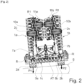
- FIG. 2 represents a front view of the agricultural machine in a position of reduced space corresponding to the road transport position.
- the side sections 1a, 1b are brought back above the central section 1c.
- the end sections 11a, 11b pivot by approximately 180° relative to the middle sections 10a, 10b and then the middle sections 10a, 10b pivot by approximately 90° relative to the central section 1c.
- the tools of the end side sections 11a, 11b are positioned in the space between the middle sections 10a, 10b.
- the two main wheels 2a, 2b belonging to the central section 1c are supported on the ground S in this transport position and extend over the central section 1c in such a way that at least one of the main wheels 2a, 2b is positioned at least partially below the respective middle section 10a, 10b.
- the side sections 1a, 1b are folded substantially vertically.
- At least one main wheel 2a, 2b is placed on each side of the median vertical plane of the agricultural machine.
- the agricultural machine shown in the Figure 2 rests on a sloping S ground.
- the Figure 3 shows the agricultural machine in an intermediate position to that of the figures 1 And 2 , one of the side sections 1a, 1b is being folded or unfolded.
- the Figure 2 shows the agricultural machine resting on sloping S ground.
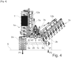
- the agricultural machine depicted on the Figure 4 corresponds to a folding agricultural machine with three sections: a central section 1a and two side sections 1a, 1b. Each side section 1a, 1b forms a single section.
- the central section 1c may be devoid of tools as can be seen in the Figure 4 or, in a form not shown, equipped with tools.
- Such an agricultural machine has a working width of four to nine meters, for example about five meters. It meets the road clearance regulations.
- figures 1 has 3 And 5 illustrate a version of the folding agricultural machine with five sections: a central section 1c, two middle sections 10a, 10b and two end sections 11a, 11b.
- Each middle section 10a, 10b and each end section 11a, 11b together form a side section 1a, 1b and are foldable relative to each other to allow the agricultural machine to comply with road clearance regulations (in transport mode).
- road clearance regulations in transport mode.
- Such an agricultural machine with five sections allows for a working width of more than nine meters, in particular around twelve meters. This is a very wide agricultural machine. If we compare these two versions of the folding agricultural machine, the side sections 1a, 1b of the version with three sections ( Figure 4 ) are therefore in some way devoid of the end sections of the version with five sections ( figures 1 has 3 , 5 ).
- the multi-section agricultural machine shown on the figures 1 has 3 is an agricultural machine configured to be towed by a tractor-type vehicle (not shown). For this purpose, it comprises an AT coupling element.
- the AT coupling element is connected to the central section 1c of the agricultural machine.
- the central section 1c extends transversely on either side of the longitudinal axis X; it is centered relative to the median vertical plane of the agricultural machine.
- the AT coupling element shown in the Figure 1 is designed in the form of a drawbar equipped at the front with a towing eye adapted for a towing ball.
- the chassis is provided with an axle with a transverse axis 20 comprising two main wheels 2a, 2b which serve as support on the ground S during transport of the machine and which are used to adjust the working depth of the tools during work.
- the first main wheel 2a and the second main wheel 2b correspond respectively to the right wheel and the left wheel, seen in the direction of travel A of the agricultural machine shown in the Figure 1 . If we take into consideration the front view of the agricultural machine as shown in the figures 2 has 4 , there right wheel, seen in the direction of travel A, is the first main wheel 2a and the left wheel corresponds to the second main wheel 2b.
- the agricultural machine rests on horizontal ground S and comprises two side sections 1a, 1b articulated on a central section 1c devoid of tools.
- the front part of the coupling element AT is adapted to be coupled to the two lower arms of the towing vehicle.
- One of the side sections 1b is being folded while the other side section 1a is folded, substantially vertically.
- the hub 21, the tire and the rim of the left wheel are not shown on the Figure 4 , only the perimeter of the left wheel is shown.
- the side section 1a extends substantially above the left wheel in its folded position. In the transport position, the side sections 1a, 1b with the tools extend into the width of the main wheels 2a, 2b.
- side sections 1a, 1b do not support secondary wheels 2c.
- each side section 1a, 1b can be made up of a single section ( Figure 4 ) or several section(s), for example two sections ( figures 1 has 3 ) and that, in the case where the side section 1a, 1b consists of several sections, it comprises a middle section 10a, 10b and at least one end section 11a, 11b.
- the end section 11a, 11b can be moved relative to the middle section 10a, 10b between a folded position and an unfolded position, for example by being pivotally mounted on the middle section 10a, 10b or, if appropriate (more than two end sections 11a, 11b) on another end section 11a, 11b.
- the end section 11a, 11b folds down against the middle section 10a, 10b ( figures 2 , 3 , 5 ), the end section 11a, 11b can preferably pivot by 180°.
- the end section 11a, 11b In the unfolded position ( Figure 1 ), the end section 11a, 11b is positioned in the extension of the middle section 10a, 10b.
- the central section 1c and the side sections 1a, 1b are then aligned and in a working configuration.
- the folding/unfolding of the side section 1a, 1b comprises the operation of folding/unfolding the middle section 10a, 10b and, where appropriate, the operation of folding/unfolding the or each end section 11a, 11b.
- the unfolding or folding of the middle section 10a, 10b and the end section 11a, 11b may be arranged randomly or in a coordinated manner.
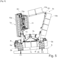
- the end section 11a, 11b is unfolded or folded at the same time as the middle section 10a, 10b ( figures 5 , 7 ) so as to allow faster unfolding/folding of the side section 1a, 1b.
- each section of the agricultural machine constitutes a supporting structure for the variety of tools that will carry out a job.
- the central section 1c being devoid of tools.
- the central section 1c may comprise tools ( figures 1 has 3 , 5 ) or be devoid of tools ( Figure 4 ).
- the central section 1c rests on the ground S by means of the main wheels 2a, 2b.
- Each side section 1a, 1b can then be moved relative to the central section 1c, in particular by being pivotally mounted, at least between the transport position and the working position.
- Each side section 1a, 1b is then folded (or folded or closed or raised) when it is moved in the direction of the working position towards the transport position and unfolded (or deployed or open) when it is moved in the direction of the transport position towards the working position.
- Each side section 1a, 1b pivots relative to the central section 1c.
- the transverse axis 20 of the axle (or of each axle) is supported by the central section 1c, i.e. by the frame-forming part of the central part 1c.
- Each side section 1a, 1b can be pivotally mounted by being articulated around a pivot of the joint R parallel (the pivot) to the longitudinal axis X of the agricultural machine or to the direction of travel A of the agricultural machine.
- the pivoting, preferably of approximately 90°, of each side section 1a, 1b is thus carried out around the pivot of the respective joint R.
- the agricultural machine can rest by its main wheels 2a, 2b on horizontal ground S ( figures 1 And 4 ) or on a slope ( figures 2 , 3 , 5 ), i.e. transversely inclined.
- the lateral section 1a, 1b where appropriate its middle section 10a, 10b, extends substantially vertically (ground S horizontal), or substantially perpendicularly (ground S horizontal or sloping), relative to the ground S.
- the lateral section 1a, 1b In the unfolded position for work, the lateral section 1a, 1b extends substantially horizontally (horizontal S ground) or approximately parallel (horizontal or sloping S ground) to the S ground.
- the agricultural machine comprises at least one main actuator 7a, 7b for driving/actuating the movement of each side section 1a, 1b ( figures 1 has 7 ). At least one first main actuator 7a can then cause the first lateral section 1a to pivot and at least one second main actuator 7b can then cause the second lateral section 1b to move.
- the agricultural machine further comprises at least one secondary actuator 8a, 8b for causing the end section 11a, 11a to pivot relative to the middle section 10a, 10b.
- each actuator 7a, 7b, 8a, 8b (main or secondary) is a double-acting cylinder.
- a double-acting cylinder conventionally comprises a rod having at one of its ends a piston movable in the body of the cylinder.
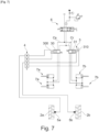
- the piston delimits two chambers of variable volume, namely a small chamber and a large chamber (see in particular the Figure 7 ).
- two actuators 7a, 7b can be used to control the folding or folding of the side sections when these support several types of tools one behind the other.
- the hydraulic diagram of the Figure 7 shows for example the use of two actuators 7a, 7b per side allowing the folding of the respective side sections 1a, 1b.
- each main actuator 7a, 7b of the double-acting cylinder type can be articulated on the one hand on the lateral section 1a, 1b and on the other hand on the central section 1c of the agricultural machine.
- Each secondary actuator 8a, 8b of the double-acting cylinder type can be articulated on the one hand on the end section 11a, 11b and on the other hand on the middle section of the lateral section 1a, 1b.
- the arrangement and operation of the main actuators 7a, 7b can be defined so that the retraction of the rod of the main cylinder 7a, 7b can actuate the folding of the lateral section 1a, 1b and that the extension of the rod of the main cylinder 7a, 7b can actuate the unfolding of the lateral section 1a, 1b.
- the arrangement and operation of the actuators 8a, 8b secondary cylinders can be defined so that the retraction of the rod of the secondary cylinder 8a, 8b can actuate the folding of the end section 11a, 11b and the extension of the rod of the secondary cylinder 8a, 8b can actuate the unfolding of the end section 11a, 11b.
- the agricultural machine further comprises an unfolding/folding control device comprising a control block 4 for controlling the control unit 3 and a measuring system connected to the control block 4 and making it possible to measure the load P1, P2 on the at least two main wheels 2a, 2b, namely the load P1 on the first main wheel 2a (or where appropriate on at least one of the first main wheels 2a) to obtain at least a first measurement and the load P2 at least on the second main wheel 2b (or where appropriate on at least one of the second main wheels 2a) to obtain at least a second measurement.
- an unfolding/folding control device comprising a control block 4 for controlling the control unit 3 and a measuring system connected to the control block 4 and making it possible to measure the load P1, P2 on the at least two main wheels 2a, 2b, namely the load P1 on the first main wheel 2a (or where appropriate on at least one of the first main wheels 2a) to obtain at least a first measurement and the load P2 at least on the second main wheel 2b (or where appropriate on at
- control block 4 is configured to be able to compare the first measurement with the second measurement and, depending on the result of the comparison, to be able to control the control unit 3 so as to allow the unfolding/folding of one and/or the other of the side sections 1a, 1b and/or to block the, or limit the speed of, unfolding/folding of one and/or the other of the side sections 1a, 1b to avoid a risk of tipping of the agricultural machine.
- the control unit 3 therefore receives instructions from the control block 4 which is configured to be able to compare the load P1, P2 measured on the first and second main wheel(s) 2a, 2b and to be able to control at least one and/or the other of the main actuators 7a, 7b, and where appropriate secondary actuators 8a, 8b, depending on the result of the comparison.
- the control unit 4 performs the comparison at least before the unfolding/folding operation, possibly during the folding/unfolding operation.
- the measurements via the sensors 5a, 5b are taken when the agricultural machine is not moving, i.e. when it is not moving. The reliability of the measurements is higher when the agricultural machine is static.
- the unfolding/folding control device is also functional when the agricultural machine is moving or not completely stopped.
- the measuring system comprises at least two measuring sensors 5a, 5b, namely at least one first sensor 5a capable and intended to measure the load P1 on the first main wheel 2a and at least one second sensor 5b capable and intended to measure the load P2 on the second main wheel 2b.
- each sensor 5a, 5b may be a force sensor, more preferably a force sensor comprising at least one strain gauge.
- each sensor 5a is located on the transverse axis 20 near the hub 21 of the corresponding first or second main wheel 2a, 2b or at a point located on the hub 21 of the corresponding first or second main wheel 2a, 2b.
- figures 2 , 4 And 5 schematically show the locations of the sensors 5a, 5b.
- the sensors 5a and 5b are arranged symmetrically with respect to the longitudinal axis X of the agricultural machine. It is understood that the first sensor 5a is located on the transverse axis 20 near the hub 21 of the first main wheel 2a or at a point located on the hub 21 of the first main wheel 2a and that the second sensor 5a is located on the transverse axis 20 near the hub 21 of the second main wheel 2a or at a point located on the hub 21 of the second main wheel 2a. In a particularly advantageous manner and to perfect the comparison of the two measurements, the sensors 5a and 5b can be arranged symmetrically with respect to the longitudinal axis X of the agricultural machine.
- the measuring system therefore comprises at least one sensor 5a, 5b configured to directly or indirectly detect the load applied to one of the main wheels 2a, 2b and at least one sensor 5b, 5a configured to directly or indirectly detect the load applied to the other of the main wheels 2b, 2a.
- the sensors 5a, 5b thus providing an indication of the weight of the associated lateral section 1a, 1b on which the main wheel 2a, 2b is supported.
- the secondary wheels 2c which are not in contact with the ground S during the folding/unfolding phases of the agricultural machine are not equipped with such sensors.
- the agricultural machine may comprise at least one bogie comprising at least two axles connected to each other by connecting elements.
- each sensor 5a, 5b may be arranged on one of the connecting elements connecting the axles.
- the tractor vehicle to which the agricultural machine according to the present invention can be coupled and hydraulically connected may include a distributor 6, as is generally the case in this type of vehicle ( figures 6 And 7 ).
- This distributor 6 has the function of directing the pressurized fluid into the various circuits of the tractor and the agricultural machine attached to the latter.
- the control unit 3 can then be further connected to the distributor 6 so as to be able to supply the main actuators 7a, 7b, and where appropriate the secondary actuators 8a, 8b, with pressurized hydraulic fluid via the control unit 3 ( figures 6 And 7 ).
- the distributor 6 can be controlled by the user or automatically by control electronics.
- the measurement operations by the measurement system and/or the measurement acquisition operations by the control block 4 and/or the processing operations, in particular comparison, by the control block 4 can be carried out according to a predetermined frequency or at each instant as soon as an unfolding/folding command is carried out by the user or automatically by control electronics. For example, a comparison could be carried out every second (1 Hz) or every half-second. In practice, since the unfolding speed of the side sections of the agricultural machine is quite fast, a suitable comparison frequency could be 10 Hz or more.
- the control electronics may comprise a control program folding/unfolding depending on the progress and position of the agricultural machine on the ground S. The comparison frequency is adapted to the technology.
- the agricultural machine can comprise two supply circuits Cr, Cs for supplying pressurized fluid to double-acting cylinders each forming one of the main actuators 7a, 7b, namely a circuit Cr for supplying the small chamber of the cylinders 7a, 7b and a circuit Cs for supplying the large chamber of the cylinders 7a, 7b.
- These two supply circuits Cr and Cs preferentially supply two cylinders 7a for actuating the first lateral section 1a and two cylinders 7b for actuating the second lateral section 1b.
- control unit 3 connected to the distributor 6 is configured to be able to direct the fluid towards one and/or the other of the lateral sections 1a, 1b, that is to say towards the two cylinders 7a of the first lateral section 1a and/or towards the two cylinders 7b of the second lateral section 1b.
- the circuit is arranged so that the two cylinders 7a, 7b actuating each lateral section 1a, 1b are supplied at the same time and with the same flow rate.
- control unit 3 comprises two distributors 30, 31, namely a first distributor 30 to allow the supply of pressurized fluid to the two cylinders 7a actuating the first lateral section 1a and a second distributor 31 to allow the supply of pressurized fluid to the two cylinders 7b actuating the second lateral section 1b.
- Each distributor 30, 31 comprises a coil 300, 310 electrically connected to the control block 4.
- Each distributor 30, 31 is therefore controlled (electrically) by the control block 4.
- each distributor 30, 31 can be a 4/2 slide distributor, i.e.
- the present invention may provide other types of distributor 30, 31, for example proportional distributors (proportional control and progressive slide) which allow the passage to the fluid to be opened progressively unlike the distributors 30, 31 with 4/2 slides which operate in all or nothing.
- proportional distributor the movement of the slide is proportional to the control (electrical signal emitted by the control block 4).
- the control block 4 connected to such a proportional distributor must therefore be adapted accordingly.
- Such a proportional distributor therefore makes it possible to obtain in the supply circuit Cr or Cs a low or high flow rate depending on the electrical control signal and therefore to adjust the unfolding/folding speed (rod extension/retraction speed).
- the present invention it is therefore always the lateral section 1a, 1b located on the side of the main wheel 2a, 2b where the load P1, P2 acting on this The latter is less (compared to the load P1, P2 exerted on the main wheel 2a, 2b located on the other side) which must be unfolded/folded as a priority.
- the lateral section 1a, 1b where the load P1, P2 exerted on the main wheel 2a, 2b is greater (compared to the load P1, P2 exerted on the main wheel 2a, 2b located on the other side) which will be blocked or whose unfolding/folding speed will be limited.
- the control block 4 may consist of an electronic card capable of managing the functions of the agricultural machine according to the present invention. It may comprise a processor and at least one memory storing a computer program comprising instructions for comparing the first and second load measurements P1, P2 carried out by the measurement and control system, depending on the result of the comparison, of the control unit 3. Where appropriate, the or one of the memories may comprise the threshold value or several selectable threshold values.
- the comparison by means of the control unit 4 of the information given by the sensors 5a, 5b present at the level of the first main wheel 2a and at the level of the second main wheel 2b makes it possible to overcome the reference frame, therefore the ground S, on which the agricultural machine rests.
- the control unit 3 is able to limit or block the unfolding/folding of a side section 1a, 1b to prevent any risk of tipping of the agricultural machine.
- the control block 4 is configured to control the control unit 3 so as to unfold the side section 1a, 1b on the side of the main wheel 2a, 2b where the detected load is less and to block the side section 1a, 1b on the side of the main wheel 2a, 2b where the detected load is greater. In this way, the risk of tipping of the agricultural machine is eliminated during the folding and/or unfolding maneuvers of the side sections 1a, 1b.
- the control unit 4 continues to receive the measurements and when the measured difference is identical to or less than the threshold value, i.e. when the side section 1a, 1b being unfolded/folded reaches a certain pivot angle, the control unit 4 will command the control unit 3 so as to initiate the unfolding/folding of the other side section 1a, 1b.
- the control unit 3 will make it possible to control the unfolding/folding sequence of the side sections 1a, 1b in order to avoid the risk of the agricultural machine tipping over.
- the method may consist of each measurement being carried out at a point located on the transverse axis 20 near the hub 21 of the corresponding first or second main wheel 2a, 2b or at a point located on the hub 21 of the corresponding first or second main wheel 2a, 2b.
- each side section 1a, 1b comprises a middle section 10a, 10b and an end section 11a, 11b
- the method may consist, by means of the control block 4, depending on the result of the comparison, in controlling the unfolding/folding of the end sections 11a, 11b offset relative to the respective middle sections 10a, 10b or at the same time as the latter.
- the present invention allows, depending on the result of a comparison of load measurement P1, P2 on the main wheels 2a, 2b of the agricultural machine to send an adequate command for the folding/unfolding of each lateral section 1a, 1b to avoid any risk of tipping of the agricultural machine and therefore to propose an agricultural machine of great stability during unfolding/folding maneuvers regardless of the reference frame on which the main wheels 2a, 2b are based.
Landscapes
- Life Sciences & Earth Sciences (AREA)
- Engineering & Computer Science (AREA)
- Mechanical Engineering (AREA)
- Soil Sciences (AREA)
- Environmental Sciences (AREA)
- Agricultural Machines (AREA)
Applications Claiming Priority (1)
| Application Number | Priority Date | Filing Date | Title |
|---|---|---|---|
| FR2314012A FR3156278B1 (fr) | 2023-12-12 | 2023-12-12 | Procédé de contrôle d’une machine agricole et une telle machine agricole |
Publications (1)
| Publication Number | Publication Date |
|---|---|
| EP4570049A1 true EP4570049A1 (de) | 2025-06-18 |
Family
ID=90122987
Family Applications (1)
| Application Number | Title | Priority Date | Filing Date |
|---|---|---|---|
| EP24218378.8A Pending EP4570049A1 (de) | 2023-12-12 | 2024-12-09 | Verfahren zur steuerung einer landmaschine und eine solche landmaschine |
Country Status (2)
| Country | Link |
|---|---|
| EP (1) | EP4570049A1 (de) |
| FR (1) | FR3156278B1 (de) |
Citations (4)
| Publication number | Priority date | Publication date | Assignee | Title |
|---|---|---|---|---|
| US20140060860A1 (en) * | 2012-08-28 | 2014-03-06 | Randall A. Maro | Folding implement frame with weight transfer |
| US20170332543A1 (en) * | 2016-05-20 | 2017-11-23 | Cnh Industrial America Llc | Agricultural tillage implement fold sequence control |
| US20180077849A1 (en) * | 2016-09-19 | 2018-03-22 | Agco Corporation | Implement load balancing system |
| US10747195B2 (en) * | 2017-10-27 | 2020-08-18 | Cnh Industrial Canada, Ltd. | System and method for controlling the actuation of wing sections of an implement during an unfolding operation |
-
2023
- 2023-12-12 FR FR2314012A patent/FR3156278B1/fr active Active
-
2024
- 2024-12-09 EP EP24218378.8A patent/EP4570049A1/de active Pending
Patent Citations (4)
| Publication number | Priority date | Publication date | Assignee | Title |
|---|---|---|---|---|
| US20140060860A1 (en) * | 2012-08-28 | 2014-03-06 | Randall A. Maro | Folding implement frame with weight transfer |
| US20170332543A1 (en) * | 2016-05-20 | 2017-11-23 | Cnh Industrial America Llc | Agricultural tillage implement fold sequence control |
| US20180077849A1 (en) * | 2016-09-19 | 2018-03-22 | Agco Corporation | Implement load balancing system |
| US10747195B2 (en) * | 2017-10-27 | 2020-08-18 | Cnh Industrial Canada, Ltd. | System and method for controlling the actuation of wing sections of an implement during an unfolding operation |
Also Published As
| Publication number | Publication date |
|---|---|
| FR3156278A1 (fr) | 2025-06-13 |
| FR3156278B1 (fr) | 2025-12-12 |
Similar Documents
| Publication | Publication Date | Title |
|---|---|---|
| CA2226656C (fr) | Machine agricole de coupe perfectionnee | |
| EP2699074B1 (de) | Landwirtschaftliche maschine mit verbesserter faltvorrichtung | |
| EP2863726A1 (de) | Verbesserte kopplungsvorrichtung und landwirtschaftliche maschine mit solch einer vorrichtung | |
| EP2457426B1 (de) | Sämaschine mit versetzten Stützelementen | |
| FR2501954A1 (fr) | Systeme de controle d'assiette pour outil ou machine et travaillant le sol et circuit de commande destine a ce systeme | |
| WO2004091282A1 (fr) | Faucheuse agricole | |
| EP3834592B1 (de) | Pflug mit mindestens einer zusätzlichen bodenbearbeitungseinrichtung | |
| EP2538762B1 (de) | Verbesserte zusammenklappbare sämaschine | |
| EP4570049A1 (de) | Verfahren zur steuerung einer landmaschine und eine solche landmaschine | |
| EP2361491B1 (de) | Sämaschine mit Einstellvorrichtungen mit verringertem Raumbedarf | |
| EP2629597B1 (de) | Erntemaschine mit einer beleuchtungsvorrichtung | |
| CA2873392A1 (fr) | Machine agricole avec un chassis perfectionne | |
| WO2011114049A1 (fr) | Semoir avec un chassis traine | |
| FR2675008A1 (fr) | Dispositif de reglage par rapport au sol d'un appareil de recolte tracte. | |
| EP0966874B1 (de) | Sähmaschine | |
| EP0966875B1 (de) | Sähmaschine | |
| EP1466516A1 (de) | Landwirtschaftliche Maschine mit zumindest einem Rad | |
| EP3973754B1 (de) | Drehpflug vom typ aufsattelpflug mit wagen oder einzelrad | |
| FR2967864A1 (fr) | Charrue semi-portee avec un organe de nettoyage de roue perfectionne | |
| EP3403481A1 (de) | Werkzeughalterahmen für die bodenbearbeitung mit begrenzter verschiebung | |
| EP3973756A1 (de) | Gezogene landwirtschaftliche erntemaschnie mit einer verstellbaren achsvorrichtung | |
| FR2967865A1 (fr) | Machine agricole a correction automatique d'assiette | |
| FR2901452A1 (fr) | Machine agricole pouvant etre attelee a l'arriere d'un tracteur par l'intermediaire d'une poutre semi-portee | |
| FR2882217A1 (fr) | Machine pour le travail du sol tractee |
Legal Events
| Date | Code | Title | Description |
|---|---|---|---|
| PUAI | Public reference made under article 153(3) epc to a published international application that has entered the european phase |
Free format text: ORIGINAL CODE: 0009012 |
|
| STAA | Information on the status of an ep patent application or granted ep patent |
Free format text: STATUS: THE APPLICATION HAS BEEN PUBLISHED |
|
| AK | Designated contracting states |
Kind code of ref document: A1 Designated state(s): AL AT BE BG CH CY CZ DE DK EE ES FI FR GB GR HR HU IE IS IT LI LT LU LV MC ME MK MT NL NO PL PT RO RS SE SI SK SM TR |
|
| STAA | Information on the status of an ep patent application or granted ep patent |
Free format text: STATUS: REQUEST FOR EXAMINATION WAS MADE |
|
| 17P | Request for examination filed |
Effective date: 20251218 |