EP4570065A1 - Selektive leistungsverwaltung in einem bienenstocküberwachungssystem - Google Patents
Selektive leistungsverwaltung in einem bienenstocküberwachungssystem Download PDFInfo
- Publication number
- EP4570065A1 EP4570065A1 EP24220301.6A EP24220301A EP4570065A1 EP 4570065 A1 EP4570065 A1 EP 4570065A1 EP 24220301 A EP24220301 A EP 24220301A EP 4570065 A1 EP4570065 A1 EP 4570065A1
- Authority
- EP
- European Patent Office
- Prior art keywords
- beehive
- equipment
- controller
- bee
- battery
- Prior art date
- Legal status (The legal status is an assumption and is not a legal conclusion. Google has not performed a legal analysis and makes no representation as to the accuracy of the status listed.)
- Pending
Links
Images


Classifications
-
- A—HUMAN NECESSITIES
- A01—AGRICULTURE; FORESTRY; ANIMAL HUSBANDRY; HUNTING; TRAPPING; FISHING
- A01K—ANIMAL HUSBANDRY; AVICULTURE; APICULTURE; PISCICULTURE; FISHING; REARING OR BREEDING ANIMALS, NOT OTHERWISE PROVIDED FOR; NEW BREEDS OF ANIMALS
- A01K47/00—Beehives
- A01K47/06—Other details of beehives, e.g. ventilating devices, entrances to hives, guards, partitions or bee escapes
-
- A—HUMAN NECESSITIES
- A01—AGRICULTURE; FORESTRY; ANIMAL HUSBANDRY; HUNTING; TRAPPING; FISHING
- A01K—ANIMAL HUSBANDRY; AVICULTURE; APICULTURE; PISCICULTURE; FISHING; REARING OR BREEDING ANIMALS, NOT OTHERWISE PROVIDED FOR; NEW BREEDS OF ANIMALS
- A01K29/00—Other apparatus for animal husbandry
- A01K29/005—Monitoring or measuring activity
Definitions
- the disclosure relates to technical equipment and to controlling the energy consumption of its components, and more in particular, the disclosure relates to equipment that supports the operation of a beehive.
- Simplified, beehives are artificial structures for honey bees to live in, and usually one hive serves a single bee colony.
- the inspection items are interrelated. For example, temperature and humidity are related to the risk that the colonies suffer from external parasitic mites, such as varroa mites.
- thermometers e.g., thermometers
- H humidity
- the sensors comprise electronic thermometers or hygrometers
- the actuators can comprise heaters and coolers, and fans to move air within the hive or to allow air flow from outside to inside and vice versa.
- Technical equipment can also be extended by sensors in combination with data transmitters.
- the beekeeper could watch parameters without having to travel. For example, the beekeeper watches weight changes. Beehives having reached certain weights are to be relocated, or are ready for harvest.
- Technical equipment can be associated with control loops that are extended to remote computers.
- the mentioned data transmitters can be updated to data receivers (i.e., "transceivers") so that the remote computer processes sensor data (from the hive) and provides control data (to the hive).
- the disclosure relates to beehive equipment for monitoring and controlling conditions at a beehive.
- the beehive equipment comprises sensors, actuators, and a controller.
- the controller is adapted to adjust the power consumption of the sensors and the actuators by selectively controlling the power consumption of sensors and actuators individually, and according to bee requirements:
- a first requirement is that a pre-defined percentage of bees survives at pre-defined phases, such as for example phases in a bee-growing season.
- a second requirement is that within the beehive, the temperature and the humidity remain within pre-defined values.
- the controller comprises a computer module that is a machine-learning tool and that has been trained with (i) data regarding operation parameters of reference bee equipment such as temperature and humidity, as well as (ii) data regarding bee activities.
- the bee activities that have been monitored prior to training define the requirements in terms, for example, survival and temperature/humidity values.
- the machine-learning tool has also been trained with data regarding a power supply unit.
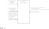
- the data regarding the operation parameters of the reference bee equipment comprise: battery parameters with voltage and current values, and actuator data, with fan ON/OFF durations, heater operation data, cooler operation data.
- the data regarding bee activities comprise, selected from the following: the number of bees obtained from sensors that are bee counters; the weight of the beehive, from sensors that are scales; weight changes, from the scales; and an indication of the quantity of honey, from sensors that are active post-harvesting.
- the machine-learning tool in the controller is implemented as an artificial neural network ANN for that network weights have been obtained during training.
- the machine-learning tool in the controller has also been trained with power parameters and has thereby been enabled to make predictions regarding: the time points in the future for that temperature values become critical being excess temperature values, and control instructions for the components to obtain control instructions at present time and for the future.
- the controller is further adapted to adjust the power consumption of a data unit.
- the controller instructs actuators to operate in full capacity during selected time-frames only.
- a further bee requirement can be that the amount of honey increases by a pre-defined increase rate.
- a method to operate beehive equipment for a beehive comprises that a heater and a cooler operate in ON/OFF mode, that a fan controls air flow inside the beehive and controls air flow from inside out and vice versa, that conditions are monitored -with sensors for temperature, humidity, and weight (collectively: condition monitor).
- condition monitor sensors for temperature, humidity, and weight
- the heater, the cooler, the fan, and the condition monitor are powered by a battery that is located at the beehive.
- the method comprises communicating data regarding conditions to a user computer, to inform a computer user about the technical status of the beehive as a technical system that is located remotely to the computer user;
- the method is characterized by monitoring the battery; and depending on the status of the battery, switching the heater, the cooler, and/or the fan off, if the battery has a status that indicates less remaining capacity.
- monitoring the battery comprises to measure the battery voltage and to determine the remaining capacity.
- Switching the heater, the cooler and/or the fan off is implemented by a controller that has a machine-learning tool and that has been trained with (i) data regarding operation parameters of reference bee equipment such as temperature and humidity, as well as (ii) data regarding bee activities, so that the following bee requirements remain satisfied: (first) a pre-defined percentage of bees survives at pre-defined phases, and (second) within the beehive, the temperature and the humidity remain within pre-defined values.
- the controller can switch between different levels of power consumption, wherein from low consumption to high consumption, the levels can be characterized by 1) a deep sleep of the controller, 2) measuring by sensors, 3) transmitting data by data units, generating sound by actuators, and 4) heating or cooling.
- the description describes a monitoring platform for remotely monitoring beehives (cf. item 101 in FIG. 1A ).
- the platform can be considered as a system with equipment at a beehive (cf. item 100 in FIG. 1B ) and with computers (cf. items 200, 300 FIG. 5 ) that are remote to the beehive.
- the operation of the platform in general, and the operation of the equipment is based on conditions at the beehive.
- the beehive equipment monitors the temperature and relative humidity of the beehive's environment (i.e., external conditions) or in the beehive itself (i.e., internal conditions). It can further monitor (internal) parameters, such as the instant weight W (i.e., the weight at a particular point in time, for processing weight data in real time and for reacting in real-time).
- the instant weight W i.e., the weight at a particular point in time, for processing weight data in real time and for reacting in real-time.
- the beehive equipment can provide heating and cooling capabilities, usually to compensate for external conditions, in winter and summer, respectively. In this way, the health state of the colony can be maintained at relatively high levels and - compared to traditional beehives without such equipment - this eventually results in higher honey yield.
- the geographical location of the beehive can be extremely remote. Therefore, the beekeeper usually can not interact with the beehive regularly.
- the equipment should have a certain autarky from the beekeeper. For example, battery-powered equipment should consume power at minimal levels so that the battery (or one battery charge) would last a whole season.
- the description explains the equipment by way of example as a method of monitoring and controlling the temperature und the relative humidity.
- the equipment comprises elements such as sensors and actuators.
- the actors are not necessarily heaters or coolers but also elements to control the air flow (such as fans, movable windows, shutters etc.).
- the energy management involves hierarchical classification of the associated components in terms of power consumption.
- An optimized method for switching on and off those components ensures longer provision of power to the heating or cooling system.
- the platform with its equipment may provide advantages at least in the following:
- the number of physical inspections per season can be reduced. Although there is no direct effect on the beehive, the overall energy consumption can be reduced as well (e.g., due to less traveling).
- Monitoring can increase the yield of honey, by providing critical information to the beekeeper. For example, the beekeeper can be informed about the weight W of the beehive.
- monitoring is combined with acting (e.g., to control temperature and humidity), it is expected that the bees have relatively better health.
- the environment within the beehive can become more "bee-friendly", which results in stronger colonies and subsequently higher honey yield.
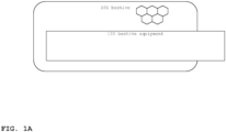
- FIGS. 1A and 1B illustrate block diagrams of beehive 101 and of beehive equipment 100.
- FIG. 1A illustrates beehive 101.
- a honeycomb just symbolizes the bees.
- Beehive equipment 100 is illustrated with some overlay to beehive 101 to symbolize that equipment 100 can be located inside beehive 101, or outside beehive 101 (e.g., in case of scales or the like, even partly below the hive).
- Equipment (and its components) can be provided to beehive 101 as an add-on.
- existing beehives can be updated with equipment 100.
- FIG. 1B illustrates a block diagram of beehive equipment 100 having components 110, 120, 130, 140 and 150.
- Beehive equipment 100 is not identical with beehive 101, but equipment and beehive form a unit. It is possible to install equipment 100 to an existing beehive.
- the components can be differentiated into sensors 110 (e.g., sensor 110-A, sensor 110-B etc.), actuators 120 (e.g., actuator 120-A, actuator 120-B etc.), at least one controller 130 (such as a microcontroller, optionally with machine-learning tool 131, cf. FIGS. 3-4 ), data units 140 (such as data transmitters, data receivers, using radio channel or cable channels), and at least one power supply unit 150, to supply electrical energy (such as for example a battery, or a connector to a power grid).
- sensors 110 e.g., sensor 110-A, sensor 110-B etc.
- actuators 120 e.g., actuator 120-A, actuator 120-B etc.
- controller 130 such as a microcontroller, optionally with machine-learning tool 131, cf. FIGS. 3-4
- data units 140 such as data transmitters, data receivers, using radio channel or cable channels
- at least one power supply unit 150 to supply electrical energy (such as for example a battery, or
- Components 110-140 are power consumers, and power supply unit 150 is a power provider.
- power refers to energy in the form of electrical energy. The figure symbolizes power consumption by thin vertical arrows from power supply unit 150 to components 110-140.
- view sensors 110, controller 130 and data unit 140 consume power, but actuators 120 do not.
- the "switches” can be controlled from controller 130 via a bus (thin horizontal line, dashed).
- a bus thin horizontal line, dashed.
- the symbols are simplified, it should be possible to selectively control the power consumption for individual components (i.e., -A, -B) separately.
- actuator 120 may consume more power than sensor 110.
- the block diagram introduces components 110-140 by its function.
- the skilled person is able to integrate components structurally.
- the function of controller 130 and of data unit 140 can be integrated to a single printed circuit board (PCB).
- PCB printed circuit board
- Components 110-140 (as wells as power supply unit 150 being a component as well) have different technical states. From a high-level perspective, states can be binary states, such as "normal operation”, and "failure”.
- a sensor provides a measurement result (or not)
- an actuator may operate or not (e.g., a fan rotates, or not because a bee may sit inside), a controller reacts on sensor readings and instructs the actuators, but it might fail.
- Data units may communicate data, or not.
- a radio transceiver in a cellular network may not be able to establish a radio channel with a base station.
- power supply unit 150 as having 3 states:
- components 110-140 can have power states, that are, for example, binary consumption states:
- a sensor should provide measurement results at sampling intervals ⁇ T. For relatively long ⁇ T, the sensor would show minimal consumption. The state could be modified by a control signal (from controller 130, a "wake-up call” to activate it) to make ⁇ T relatively short (thereby changing to normal or excess consumption)
- an actuator could be switched from normal consumption to minimal consumption (e.g., by switching off a fan).
- controller 130 comprises sub-components such as RAM memory, one or more processors such as CPU and co-processor, and communication tools (e.g., radio transceivers) and so on. Some of these sub-components can be activated or deactivated. For example, the content of the RAM memory can be moved to permanent memory so that the RAM can be switched off. Or, the co-processor can be configured in ultra-low-power (ULP) mode to take sensor readings and wake up the CPU as needed.
- ULP ultra-low-power
- the skilled person usually uses the sleep metaphor to identify operation modes by energy consumption (e.g., from highest to lowest: “active mode”, “light sleep”, “deep sleep”, “hibernate”).
- controller 130 could operate in “sleep mode” or could operate in “active mode”. While the activation or deactivation of sub-components can be arranged by the operating system of the controller (e.g., its firmware), it would also be possible to consider the sub-components for that power is managed as described herein.
- Data units could operate at different transmission time intervals (similar to ⁇ T of the sensors). In a power saving mode, a data unit communicates less data than in normal mode.
- power supply unit 150 does not have consumption states, but has provision states (e.g., rated, low power, no power). Depending on the implementation, the states is more passively to determine but not actively to be modified. (Switching to a back-up battery would increase the power capacity, but having an extra battery is usually no possible.)
- Power supply unit 150 can be implemented, for example, by
- the skilled person can also implement power supply unit 150 as a combination thereof.
- the state of power supply unit 150 has influence to the components 110-140, for "battery only” implementation for example in the following:
- the state may depend on the temperature. Some batteries may recover. For example, a battery may drop to "low power” in a cold night, but would recover to "rated power” the following day. But for simplicity of illustration, it should be assumed that batteries change from “rated” to "low” to “no” in that order, not vice versa.
- a state-of-the art approach to address battery insufficiency with over-dimensioning the battery is not desired.
- the battery could have a relatively high capacity so that at the end of the season it would still have a substantial charge in reserve.
- controller 130 interacts with sensors 110, actuators 120 and data units 140 to distribute power. This can comprise that some components would have to be deactivated (or semi-deactivated).
- controller 130 can apply rules that are either
- FIG. 2 illustrates bee parameters over time.
- the progress of time should correspond to a bee-growing season.
- honey should be within pre-defined increase rates.
- a higher yield is more than welcome, but a weight increase may not be caused by extra honey only.
- the wooden structure of the beehive may absorb rain water. Eventually, someboby may place a stone on top of the beehive. With relatively short sampling intervals of a few hours, the resulting sudden weight change can easily be regognized as an event that is not related to the honey production by the bees.
- the bee parameters can be regarded as overall constraints that influence the amount of honey that eventually could be harvested.
- the bee parameters change over time, here indicated with the progress of the season.
- the temperature should be within a certain "allowed” range, wherein deviations into a “non allowed” range need to be avoided (at least during predefined time-intervals).
- the bee parameters can be obtained empirically. To stay with the temperature, the medium value in the "allowed range" would be the set point for the temperature control loop.
- controlling the temperature requires energy, for example for sensor 110-A being an electronic thermometer, actuator 120-A being a cooler, and so on.
- the description takes the temperature as an example for a parameter that would change if the state of a component would change.
- a state change (of the battery) could disable the operation of a particular component.
- the cooler i.e. an actuator
- the temperature would raise as indicated by an arrow, but would eventually go beyond the maximal temperature, at t2.
- controller 130 could pro-actively switch off the cooler, to save energy. Or, in a variation, controller 130 could eventually let the cooler operate at a power saving mode.
- controller 130 can operate according to pre-defined rule
- the rule can be obtained by machine-learning (ML).
- controller would use a machine-learning tool, details are to be explained with FIG. 3 (training), and FIG. 4 (operating the trained ML tool).
- An ML-tool can be implemented to provide an input-to-output function based on computation weights that are identified during training.
- the ML-tool can be an artificial neural network (ANN) for that network weights are identified by applying training data to the network input and to the network output (i.e., training).
- ANN artificial neural network
- FIG. 3 illustrates a block diagram of machine-learning tool 131 under training.
- the tool can be implemented as a computer module.
- During training is receives historical data, amount them
- ML-tool 131 is thereby enabled to make predictions, among them the following:
- FIG. 4 illustrates a block diagram of machine-learning tool 131 being in use in controller 130 to control the power-consumption of the components.
- FIG. 5 illustrates an overview to a system (i.e., the above-mentioned platform), with the following:
- FIG. 5 illustrates single components, it is possible to provide the system with multiple hives (and multiple equipment 100 per hive).
- Processing data from multiple equipment (and from multiple seasons) can be required for training the machine-learning unit (cf. FIGS. 3-4 ).
- the ML units can be trained within computer 200, but can be used in controller 130 (of equipment 100).
- environmental conditions not only influence the health of the bees, but also influence the operation of the equipment.
- relatively high temperatures and humidity may be harmful to the components.
- high temperatures in summer or cold temperatures in winter highly affect the battery performance.
- sensors 110 measure parameters that are - from an overall perspective - are related to the honey yield.
- Sensors 110 can be, for example, the following: Temperature sensors measure the temperature. It is convenient to have different sensors for the inside temperature and for outside temperature. Also, sensors would be distributed to different locations (e.g., near the honeycomb). As explained with FIG. 2 , the temperature can be a parameter that is related to the well-being of the bees.
- Humidity sensors measure the humidity, and humidity within certain tolerance is important as well.
- Weight sensors measure the weight W of beehive 101 in total (i.e. with equipment 100), or of components (such as bee nests) in particular.
- the overall weight of the beehive changes over time.
- the bees carry pollen and - much simplified - a daily weight increase (or decrease, delta in general) can be estimated by a function with:
- Weight saturation i.e. the daily wight reaches an end value
- beehive 100 should be located to a different environment (where higher yield increase is expected).
- the weight W is a highly dynamic parameter. Even under that assumption (simplified assumption, hypothesis) that other parameters would be constant (e.g., parameters such as the number of bees, the weight of pollen and honey, food, etc.), the following phenomenon can be observed: As freshly made honey itself contains high levels of water that at some point within the same day the water evaporates. The weight W would therefore decrease due to this evaporation phenomenon alone. (With a suitable sampling interval, the weight sensor can be used to detect that phenomenon.)
- Such a weight change monitored over a couple of hours can serve as an indicator for the beekeeper, and represents the state of beehive 100.
- monitoring changes requires to measure W in repetitions ( ⁇ T, sampling interval or “sampling rate” etc.) and communicating W data to the beekeepers (via data units 140).
- Animal sensors may detect the presence of animals that act as honey predators. The potential presence of animals depends on the geography, and animals in question are, for example, wild bears and wild hogs. As the animals may take away some honey (and may damage the hive), there is a desired to act accordingly.
- Other sensors can be provided to track events such as, for example, opening the hive by a non-authorized person.
- a location sensor e.g., a GPS sensor
- sampling intervals of sensors depends on the phenomena to be monitored. As sensing requires power, the sampling intervals would be selected to be as long as possible but still short enough for monitoring the phenomena in appropriate time granularity. Different sensors usually use different sampling intervals.
- recording or transmitting sound uses a sampling frequency for sounds (e.g., 20.000 Hz or higher), but such a sound sensor does not have to be active all the time (its operation can be interrupted so same energy, e.g. one minute in on-mode for recording or transmitting, one minute in off-mode). It is also possible to intermediately store sound data to transmitting audio data at a later point in time.
- the battery state can be determined by a battery status sensor. It can be integrated into the battery. It is also possible to run a pre-defined test-scheme under control of controller 130.
- Testing the status of a battery is known and established in the art. For example, vehicles batteries are inspected at vehicle service stations. The battery state is determined for a current point in time t.
- the battery state can be described by parameters, such as for example,
- Heaters can be implemented by resistor heaters. The skilled person knows how to keep the bees in distance from the heaters (to avoid damages to the bees).
- Coolers can be implemented in a variety of ways, for example by the following:
- the operation mode of the actuators can be season-dependent. For example, equipment 100 would operate in winter mode (remove humidity from hive 101 but add heat), or in summer mode (remove humidity and heat).
- Sound generators may deter animals. There is - however - a constraint that the duration of sounds must be limited (for example, in sound pressure, in duration).
- Animal deterrence may be implemented otherwise, such as by having the beehive fenced with electric pasture fences or the like.
- actuators 120 are expected to be more energy consuming.
- Some of the actuators can be deactivated to save energy, according to the bee parameters (cf. FIG. 2 ).
- Some of the actuators are not related to the bee parameters.
- the risk of an animal attack may not be related to the temperature or to the humidity, but may be estimated otherwise.
- Sound generators are a candidate for being switched off (or being activated only for short time intervals).
- unit 150 could be implemented with a battery.
- the battery may have the function of a back-up battery.
- the capacity of the battery is a relevant parameter. It can be given in kWh or other units), but also in a time interval (cf. the inspection interval)
- the age of the battery is technical parameter. For example, a 3 years old battery that has been gone to a couple deep cycles most likely will last shorter (for example, every year the battery performs at 90% of the previous year).
- a further parameter is the frequency by that the battery does supply power to the components. This as an analogy to the sampling frequency of a sensor.
- the battery was a battery with a 7.2Ah rated capacity.
- the state was determined by measurement with a one-hour sampling rate (or sampling interval). This setup went through during a particular season (from February to November, 8.5 months). In the following season, the same physical battery lasted for almost 8 months. In other words, due to battery aging, the state of the battery changed earlier (to failure).
- the battery can be a LiFePO 4 battery (Lithium iron phosphate) battery.
- the battery can be a battery of any type as long as it meets the electrical, environmental and physical requirements.
- the LiFePO 4 battery was selected due to high performance, safety, and relatively low weight.
- the overall power consumption can be estimated as the sum ⁇ of the consumption for individual operation events.
- an event can be the operation of the heater during a number of hours.
- the controller can instruct some actuators act according to a particular value.
- the controller could instruct a multi-element heater to operate fully (e.g. all elements are powered) or to operate partially (e.g., some elements only).
- the heat dissipation (and hence the power consumption) of the transistor is lower for ON/OFF (i.e., the transistor being a switch, pulse-width modulation) and higher for transistors being amplifiers.
- Equipment 100 can have a heater (i.e., and cooler) to operate in ON/OFF mode (cf. the pulse-width modulation).
- a fan is provided to control air flow inside the beehive, and/or flow from inside out and vice versa.
- a condition monitor i.e., sensors for temperature, humidity, weight
- communicates data regarding conditions to a remote computer cf. FIG. 5 item 200 and 300 so that a computer user 390 can be informed about the technical status of the beehive as a technical system.
- the heater, the fan, and the condition monitor are powered by a battery that is located at the beehive.
- the method can be characterized by the following: monitoring the battery as well (e.g., voltage, or conducting tests similar to that for a car battery in the service station, optionally transmitting), and depending on the status of the battery (remaining capacity e.g., charged, less charged), switching the heater and/or fan off if the battery has a status that indicates less remaining capacity.
- FIG. 6 illustrates an example of a generic computer device which may be used with the techniques described here.
- FIG. 6 is a diagram that shows an example of a generic computer device 900 and a generic mobile computer device 950, which may be used with the techniques described here.
- Computing device 900 is intended to represent various forms of digital computers, such as laptops, desktops, workstations, personal digital assistants, servers, blade servers, mainframes, and other appropriate computers.
- Generic computer device may 900 correspond to the computers that have been illustrated by other figures.
- Computing device 950 is also intended to represent various forms of mobile devices, such as personal digital assistants, cellular telephones, smart phones, driving assistance systems or board computers of vehicles and other similar computing devices.
- computing device 950 may be used as a frontend by a user to interact with the computing device 900.
- the components shown here, their connections and relationships, and their functions, are meant to be exemplary only, and are not meant to limit implementations of the inventions described and/or claimed in this document.
- Computing device 900 includes a processor 902, memory 904, a storage device 906, a high-speed interface 908 connecting to memory 904 and high-speed expansion ports 910, and a low speed interface 912 connecting to low speed bus 914 and storage device 906.
- Each of the components 902, 904, 906, 908, 910, and 912 are interconnected using various busses, and may be mounted on a common motherboard or in other manners as appropriate.
- the processor 902 can process instructions for execution within the computing device 900, including instructions stored in the memory 904 or on the storage device 906 to display graphical information for a GUI on an external input/output device, such as display 916 coupled to high speed interface 908.
- multiple processors and/or multiple buses may be used, as appropriate, along with multiple memories and types of memory.
- multiple computing devices 900 may be connected, with each device providing portions of the necessary operations (e.g., as a server bank, a group of blade servers, or a multi-processor system).
- the memory 904 stores information within the computing device 900.
- the memory 904 is a volatile memory unit or units.
- the memory 904 is a non-volatile memory unit or units.
- the memory 904 may also be another form of computer-readable medium, such as a magnetic or optical disk.
- the storage device 906 is capable of providing mass storage for the computing device 900.
- the storage device 906 may be or contain a computer-readable medium, such as a floppy disk device, a hard disk device, an optical disk device, or a tape device, a flash memory or other similar solid state memory device, or an array of devices, including devices in a storage area network or other configurations.
- a computer program product can be tangibly embodied in an information carrier.
- the computer program product may also contain instructions that, when executed, causes the computer to perform one or more methods, such as those described above.
- the information carrier is a computer-or machine-readable medium, such as the memory 904, the storage device 906, or memory on processor 902.
- the high speed controller 908 manages bandwidth-intensive operations for the computing device 900, while the low speed controller 912 manages lower bandwidth-intensive operations.
- the high-speed controller 908 is coupled to memory 904, display 916 (e.g., through a graphics processor or accelerator), and to high-speed expansion ports 910, which may accept various expansion cards (not shown).
- low-speed controller 912 is coupled to storage device 906 and low-speed expansion port 914.
- the low-speed expansion port which may include various communication ports (e.g., USB, Bluetooth, Ethernet, wireless Ethernet) may be coupled to one or more input/output devices, such as a keyboard, a pointing device, a scanner, or a networking device such as a switch or router, e.g., through a network adapter.
- input/output devices such as a keyboard, a pointing device, a scanner, or a networking device such as a switch or router, e.g., through a network adapter.
- the computing device 900 may be implemented in a number of different forms, as shown in the figure. For example, it may be implemented as a standard server 920, or multiple times in a group of such servers. It may also be implemented as part of a rack server system 924. In addition, it may be implemented in a personal computer such as a laptop computer 922. Alternatively, components from computing device 900 may be combined with other components in a mobile device (not shown), such as device 950. Each of such devices may contain one or more of computing device 900, 950, and an entire system may be made up of multiple computing devices 900, 950 communicating with each other.
- Computing device 950 includes a processor 952, memory 964, an input/output device such as a display 954, a communication interface 966, and a transceiver 968, among other components.
- the device 950 may also be provided with a storage device, such as a microdrive or other device, to provide additional storage.
- a storage device such as a microdrive or other device, to provide additional storage.
- Each of the components 950, 952, 964, 954, 966, and 968 are interconnected using various buses, and several of the components may be mounted on a common motherboard or in other manners as appropriate.
- the processor 952 can execute instructions within the computing device 950, including instructions stored in the memory 964.
- the processor may be implemented as a chipset of chips that include separate and multiple analog and digital processors.
- the processor may provide, for example, for coordination of the other components of the device 950, such as control of user interfaces, applications run by device 950, and wireless communication by device 950.
- Processor 952 may communicate with a user through control interface 958 and display interface 956 coupled to a display 954.
- the display 954 may be, for example, a TFT LCD (Thin-Film-Transistor Liquid Crystal Display) or an OLED (Organic Light Emitting Diode) display, or other appropriate display technology.
- the display interface 956 may comprise appropriate circuitry for driving the display 954 to present graphical and other information to a user.
- the control interface 958 may receive commands from a user and convert them for submission to the processor 952.
- an external interface 962 may be provide in communication with processor 952, so as to enable near area communication of device 950 with other devices.
- External interface 962 may provide, for example, for wired communication in some implementations, or for wireless communication in other implementations, and multiple interfaces may also be used.
- the memory 964 stores information within the computing device 950.
- the memory 964 can be implemented as one or more of a computer-readable medium or media, a volatile memory unit or units, or a non-volatile memory unit or units.
- Expansion memory 984 may also be provided and connected to device 950 through expansion interface 982, which may include, for example, a SIMM (Single In Line Memory Module) card interface.
- SIMM Single In Line Memory Module
- expansion memory 984 may provide extra storage space for device 950, or may also store applications or other information for device 950.
- expansion memory 984 may include instructions to carry out or supplement the processes described above, and may include secure information also.
- expansion memory 984 may act as a security module for device 950, and may be programmed with instructions that permit secure use of device 950.
- secure applications may be provided via the SIMM cards, along with additional information, such as placing the identifying information on the SIMM card in a non-hackable manner.
- the memory may include, for example, flash memory and/or NVRAM memory, as discussed below.
- a computer program product is tangibly embodied in an information carrier.
- the computer program product contains instructions that, when executed, perform one or more methods, such as those described above.
- the information carrier is a computer- or machine-readable medium, such as the memory 964, expansion memory 984, or memory on processor 952 that may be received, for example, over transceiver 968 or external interface 962.
- Device 950 may communicate wirelessly through communication interface 966, which may include digital signal processing circuitry where necessary. Communication interface 966 may provide for communications under various modes or protocols, such as GSM voice calls, SMS, EMS, or MMS messaging, CDMA, TDMA, PDC, WCDMA, CDMA2000, or GPRS, among others. Such communication may occur, for example, through radio-frequency transceiver 968. In addition, short-range communication may occur, such as using a Bluetooth, WiFi, or other such transceiver (not shown). In addition, GPS (Global Positioning System) receiver module 980 may provide additional navigation- and location-related wireless data to device 950, which may be used as appropriate by applications running on device 950.
- GPS Global Positioning System
- Device 950 may also communicate audibly using audio codec 960, which may receive spoken information from a user and convert it to usable digital information. Audio codec 960 may likewise generate audible sound for a user, such as through a speaker, e.g., in a handset of device 950. Such sound may include sound from voice telephone calls, may include recorded sound (e.g., voice messages, music files, etc.) and may also include sound generated by applications operating on device 950.
- Audio codec 960 may receive spoken information from a user and convert it to usable digital information. Audio codec 960 may likewise generate audible sound for a user, such as through a speaker, e.g., in a handset of device 950. Such sound may include sound from voice telephone calls, may include recorded sound (e.g., voice messages, music files, etc.) and may also include sound generated by applications operating on device 950.
- the computing device 950 may be implemented in a number of different forms, as shown in the figure. For example, it may be implemented as a cellular telephone 980. It may also be implemented as part of a smart phone 982, personal digital assistant, or other similar mobile device.
- implementations of the systems and techniques described here can be realized in digital electronic circuitry, integrated circuitry, specially designed ASICs (application specific integrated circuits), computer hardware, firmware, software, and/or combinations thereof.
- ASICs application specific integrated circuits
- These various implementations can include implementation in one or more computer programs that are executable and/or interpretable on a programmable system including at least one programmable processor, which may be special or general purpose, coupled to receive data and instructions from, and to transmit data and instructions to, a storage system, at least one input device, and at least one output device.
- the systems and techniques described here can be implemented on a computer having a display device (e.g., a CRT (cathode ray tube) or LCD (liquid crystal display) monitor) for displaying information to the user and a keyboard and a pointing device (e.g., a mouse or a trackball) by which the user can provide input to the computer.
- a display device e.g., a CRT (cathode ray tube) or LCD (liquid crystal display) monitor
- a keyboard and a pointing device e.g., a mouse or a trackball
- Other kinds of devices can be used to provide for interaction with a user as well; for example, feedback provided to the user can be any form of sensory feedback (e.g., visual feedback, auditory feedback, or tactile feedback); and input from the user can be received in any form, including acoustic, speech, or tactile input.
- the systems and techniques described here can be implemented in a computing device that includes a back end component (e.g., as a data server), or that includes a middleware component (e.g., an application server), or that includes a front end component (e.g., a client computer having a graphical user interface or a Web browser through which a user can interact with an implementation of the systems and techniques described here), or any combination of such back end, middleware, or front end components.
- the components of the system can be interconnected by any form or medium of digital data communication (e.g., a communication network). Examples of communication networks include a local area network ("LAN”), a wide area network (“WAN”), and the Internet.
- LAN local area network
- WAN wide area network
- the Internet the global information network
- the computing device can include clients and servers.
- a client and server are generally remote from each other and typically interact through a communication network.
- the relationship of client and server arises by virtue of computer programs running on the respective computers and having a client-server relationship to each other.
Landscapes
- Life Sciences & Earth Sciences (AREA)
- Environmental Sciences (AREA)
- Animal Husbandry (AREA)
- Biodiversity & Conservation Biology (AREA)
- Biophysics (AREA)
- Feedback Control In General (AREA)
Applications Claiming Priority (1)
| Application Number | Priority Date | Filing Date | Title |
|---|---|---|---|
| EP23217378 | 2023-12-15 |
Publications (1)
| Publication Number | Publication Date |
|---|---|
| EP4570065A1 true EP4570065A1 (de) | 2025-06-18 |
Family
ID=89223386
Family Applications (1)
| Application Number | Title | Priority Date | Filing Date |
|---|---|---|---|
| EP24220301.6A Pending EP4570065A1 (de) | 2023-12-15 | 2024-12-16 | Selektive leistungsverwaltung in einem bienenstocküberwachungssystem |
Country Status (1)
| Country | Link |
|---|---|
| EP (1) | EP4570065A1 (de) |
Citations (3)
| Publication number | Priority date | Publication date | Assignee | Title |
|---|---|---|---|---|
| US20170360010A1 (en) * | 2016-06-16 | 2017-12-21 | Best Bees Company | Smart beehive system and method of operating the same |
| US20190373857A1 (en) * | 2017-02-27 | 2019-12-12 | Agersens Pty Ltd | Wearable apparatus for an animal |
| EP3616508A1 (de) * | 2018-08-31 | 2020-03-04 | Invoxia | Verfahren und system zur überwachung von tieren |
-
2024
- 2024-12-16 EP EP24220301.6A patent/EP4570065A1/de active Pending
Patent Citations (3)
| Publication number | Priority date | Publication date | Assignee | Title |
|---|---|---|---|---|
| US20170360010A1 (en) * | 2016-06-16 | 2017-12-21 | Best Bees Company | Smart beehive system and method of operating the same |
| US20190373857A1 (en) * | 2017-02-27 | 2019-12-12 | Agersens Pty Ltd | Wearable apparatus for an animal |
| EP3616508A1 (de) * | 2018-08-31 | 2020-03-04 | Invoxia | Verfahren und system zur überwachung von tieren |
Similar Documents
| Publication | Publication Date | Title |
|---|---|---|
| US11551154B1 (en) | Predictive power management in a wireless sensor network | |
| Sharma et al. | Maximization of wireless sensor network lifetime using solar energy harvesting for smart agriculture monitoring | |
| US10903668B2 (en) | Systems and methods for management and monitoring of energy storage and distribution | |
| CN110495221B (zh) | 功率高效基站 | |
| Zacepins et al. | Development of internet of things concept for precision beekeeping | |
| WO2017199604A1 (ja) | 制御装置、制御方法及び蓄電制御装置 | |
| Srbinovski et al. | Energy aware adaptive sampling algorithm for energy harvesting wireless sensor networks | |
| Musilek et al. | Intelligent energy management for environmental monitoring systems | |
| JP6826762B2 (ja) | デマンド監視装置、デマンド監視システム、デマンド監視方法およびデマンド監視プログラム | |
| Yamawaki et al. | Battery life estimation of sensor node with zero standby power consumption | |
| Wu et al. | Design and field test of an autonomous IoT WSN platform for environmental monitoring | |
| CN117536902A (zh) | 风扇驱动控制方法、装置、风扇设备及可读存储介质 | |
| Shen et al. | EFCon: Energy flow control for sustainable wireless sensor networks | |
| EP4570065A1 (de) | Selektive leistungsverwaltung in einem bienenstocküberwachungssystem | |
| Mohanty et al. | bSlight 2.0: Battery-free sustainable smart street light management system | |
| Murphy et al. | An automatic, wireless audio recording node for analysis of beehives | |
| Kho et al. | Decentralised adaptive sampling of wireless sensor networks | |
| Pikri et al. | IoT-based temperature and humidity real-time monitoring system for beekeeping using LoRa technology | |
| Vieira et al. | An energy management method of sensor nodes for environmental monitoring in Amazonian Basin | |
| KR20210027963A (ko) | 모바일을 이용한 시설 하우스 환경 관리 시스템 및 방법 | |
| Janković et al. | Improving energy usage in energy harvesting wireless sensor nodes using weather forecast | |
| Nagar et al. | An efficient design of IoT enables wireless sensor network for energy optimization in the agriculture sector | |
| Cesarini et al. | Experimental validation of energy harvesting-system availability improvement through battery heating | |
| Viehweger et al. | Energy profile analysis by simulation for the design of energy harvesting systems | |
| KR102886054B1 (ko) | 넷 제로 스마트 그린 플랫폼에서 전력 분배를 제어하는 시스템 |
Legal Events
| Date | Code | Title | Description |
|---|---|---|---|
| PUAI | Public reference made under article 153(3) epc to a published international application that has entered the european phase |
Free format text: ORIGINAL CODE: 0009012 |
|
| STAA | Information on the status of an ep patent application or granted ep patent |
Free format text: STATUS: THE APPLICATION HAS BEEN PUBLISHED |
|
| AK | Designated contracting states |
Kind code of ref document: A1 Designated state(s): AL AT BE BG CH CY CZ DE DK EE ES FI FR GB GR HR HU IE IS IT LI LT LU LV MC ME MK MT NL NO PL PT RO RS SE SI SK SM TR |
|
| STAA | Information on the status of an ep patent application or granted ep patent |
Free format text: STATUS: REQUEST FOR EXAMINATION WAS MADE |
|
| 17P | Request for examination filed |
Effective date: 20251217 |