EP4570151A1 - Distributeur de savon solide - Google Patents
Distributeur de savon solide Download PDFInfo
- Publication number
- EP4570151A1 EP4570151A1 EP23215608.3A EP23215608A EP4570151A1 EP 4570151 A1 EP4570151 A1 EP 4570151A1 EP 23215608 A EP23215608 A EP 23215608A EP 4570151 A1 EP4570151 A1 EP 4570151A1
- Authority
- EP
- European Patent Office
- Prior art keywords
- solid soap
- soap dispenser
- dispenser according
- housing
- threaded spindle
- Prior art date
- Legal status (The legal status is an assumption and is not a legal conclusion. Google has not performed a legal analysis and makes no representation as to the accuracy of the status listed.)
- Granted
Links
Images



Classifications
-
- A—HUMAN NECESSITIES
- A47—FURNITURE; DOMESTIC ARTICLES OR APPLIANCES; COFFEE MILLS; SPICE MILLS; SUCTION CLEANERS IN GENERAL
- A47K—SANITARY EQUIPMENT; ACCESSORIES THEREFOR, e.g. TOILET ACCESSORIES
- A47K5/00—Holders or dispensers for soap, toothpaste or the like
- A47K5/06—Dispensers for soap
- A47K5/08—Dispensers for soap for solid soap
- A47K5/09—Dispensers for soap for solid soap with means for scraping or grating
-
- A—HUMAN NECESSITIES
- A47—FURNITURE; DOMESTIC ARTICLES OR APPLIANCES; COFFEE MILLS; SPICE MILLS; SUCTION CLEANERS IN GENERAL
- A47K—SANITARY EQUIPMENT; ACCESSORIES THEREFOR, e.g. TOILET ACCESSORIES
- A47K2201/00—Details of connections of bathroom accessories, e.g. fixing soap or towel holder to a wall
- A47K2201/02—Connections to a wall mounted support
Definitions
- the invention relates to a solid soap dispenser, comprising a housing with a housing cover and an outlet opening, a grating device for grating a solid soap and a conveying device for conveying a solid soap in the direction of the grating device, wherein the conveying device and the grating device are arranged within the housing and the grating device is located near the outlet opening.
- Liquid shampoo dispensers in various designs are well-known, especially in the hotel industry. These are usually mounted directly on the wall or on wall-mounted fixtures. In private homes, soap dispensers are often used as mobile stand-alone models next to the sink.
- the invention described here has set itself the task of providing a solid soap dispenser with which, in particular, the disadvantages of the prior art shown are eliminated.
- the invention described here is a solid soap dispenser, comprising a housing with a housing cover and an outlet opening, a grating device for grating a solid soap, and a conveying device for conveying a solid soap in the direction of the grating device, wherein the conveying device and the grating device are arranged within the housing and the grating device is located near the outlet opening.
- the solid soap dispenser according to the invention is characterized in that the conveying device is constructed from a threaded spindle and a feed plate seated on the threaded spindle, wherein the threaded spindle opens into the grating device and the grating device is connected to is operatively connected to an actuating element for actuating the rasp device, wherein upon actuation of the actuating element the threaded spindle is rotatable and the feed plate is displaceable along the threaded spindle, wherein the threaded spindle has a connecting element at each of its two ends for connecting the threaded spindle to the rasp device.
- the solid soap inserted has a recess or bore running through its center for the threaded spindle.
- the feed plate is located on the rasping device.
- such a connecting element is provided at each end of the threaded spindle, after the feed plate has been completely moved to one end of the threaded spindle, the threaded spindle can simply be removed by one person after removing the housing cover from the housing of the solid soap dispenser, rotated, fitted with a new longitudinally drilled piece of solid soap and then reconnected to the rasp device by means of the connecting element.
- this could be a recess on the threaded spindle that complements the rasp device, so that the threaded spindle is simply inserted into, for example, a groove in the rasp device.
- other complementary connection types are also conceivable, particularly those based on the key-lock principle, which can be easily separated from each other.
- the invention provides, in an advantageous embodiment, that the conveyor device is accommodated in a guide device with at least one guide element, with which any movement or tilting of the solid soap within the housing or along the threaded spindle upon actuation of the actuating element and grating of the solid soap on the grating device is prevented.
- the guide device itself is preferably designed in the form of a housing within the solid soap dispenser housing.
- the guide device is designed in one piece, with the guide device particularly preferably being manufactured by injection molding.
- the guide device is made of a transparent plastic, for example polyethylene terephthalate (PET), polyacrylic, polystyrene or polycarbonate.
- At least one projecting web can serve as a guide element in the guide device, which cants or blocks the solid soap on one side or engages in a recess provided for this purpose in the solid soap.
- this projecting web can be arranged directly on the inside of the housing of the solid soap dispenser.
- the solid soap with its recesses and the guide device with its guide elements are coordinated with one another, so that no other solid soap can be used with the guide device. This can, for example, prevent Solid soap is not filled or used, but only a suitable solid soap can be used.
- a rasping device consisting of several webs arranged at the outlet opening, wherein the webs have cutting edges and/or cutting teeth, preferably crescent-shaped cutting teeth, on the side facing the housing cover, can reliably dispense uniformly sized and aesthetically pleasing pieces of soap.
- the webs are arranged in a star shape toward the center of the housing.
- the cutting edges and/or cutting teeth of one bar are offset from the cutting edges and/or cutting teeth of another bar. This ensures that the entire contact surface of the solid soap is grated, thus ensuring even removal of the solid soap.
- the housing of the solid soap dispenser can be made of metal or plastic, preferably recycled plastic, making the soap dispenser both robust and durable. When metal is used, it also leaves a high-quality impression on the user. Furthermore, it can be adapted to the respective location, for example, the shower or sink. It is also conceivable for the outlet to have a funnel shape to direct the soap shavings into the palm of a user. This can be integrated into the actuating element. Furthermore, in a preferred embodiment, the actuating element can have locking lugs with which the actuating element can be releasably connected to the housing.
- the solid soap dispenser according to the invention can furthermore have a fill level indicator on the housing.
- This is preferably a fill level indicator with a transparent viewing window, which is advantageously arranged just before the grating device, wherein in this case the feed plate is most preferably in a signal color, in particular red.
- the red feed plate is located just before the grating device and can be seen through the transparent viewing window.
- the actuating element coupled or operatively connected to the rasping device can be a rotating ring arranged on the housing, which particularly preferably has gripping bars.
- the latter enable safe handling even when a user's hands are wet, should the solid soap dispenser be installed in a damp room, such as the shower.
- a further advantageous embodiment of the invention provides for the housing cover to be watertight and theft-proof. Watertightness can be achieved, for example, by an appropriate elastic seal on the housing cover, which engages in a groove provided on the housing.
- a key lock integrated into the housing cover is conceivable as an embodiment of a suitable theft protection device.
- any other suitable type of device for theft protection or sealing of the solid soap dispenser is also possible.
- the housing lid of the solid soap dispenser according to the invention can be opened only with a key specially adapted to the solid soap dispenser.
- This key has a shape adapted to the housing and an engagement element that engages in a recess provided in the housing, allowing the housing lid to be rotated from the closed position to an open position.
- the invention provides for an electric motor to be assigned to the rasping device, which is data-connected to a motion sensor arranged at the outlet opening, so that when the motion sensor is triggered, the electric motor is controlled by the motion sensor and the rasping device is actuated by the electric motor.
- the electric motor and the motion sensor can be powered by batteries and/or accumulators. These can be integrated, for example, into the housing, preferably on one side of the housing or into the housing cover.
- the solid soap dispenser can have a fastening device for attaching the solid soap dispenser to a wall.
- This fastening device can advantageously consist of a fastening element arranged on the housing and a suitable holder, wherein the holder can be attached to a wall using conventional mounting means, for example, screws and dowels.
- the invention provides for the solid soap dispenser in an advantageous embodiment that the holder has a storage surface for storing, for example, shower utensils.
- the storage area can preferably have a splash edge to prevent utensils placed thereon from slipping due to a splash of water or a film of water on the storage area.
- the storage area can also have a slight incline towards the wall, with which any water on the storage area is directed towards the wall and, with a particularly preferably minimal distance from the wall, which can be achieved, for example, by means of a suitable fastening means, any excess water can be drained away through this formed passage.
- FIGS 1 to 5 show an embodiment of a solid soap dispenser 1 according to the invention in several views.
- the solid soap dispenser 1 has a housing 2, which is closed at the top by a housing cover 3 and has an outlet opening 4 on the underside. Furthermore, a fastening element 7 is arranged on the housing 2, with which the solid soap dispenser 1 can be mounted on a wall with a holder 21.
- an actuating element 17 in the form of a rotating ring with arranged on several handle bars 18. With this actuating element 17, the rasping device 9 can be actuated and the solid soap 10 can be grated, whereby the solid soap rasps can fall from the outlet opening 4 into the hand of a user.
- the solid soap 10 has a recess or bore running through the center for the threaded spindle 13 as well as two opposite recesses 8 into which the guide elements (not shown) of the guide device 12 engage in order to prevent twisting of the solid soap 10.
- the housing 2 in this embodiment has a viewing window 5 with a fill level indicator 6.
- the housing cover 3 has lock symbols and a line marking so that a user can easily determine whether the housing cover 3 is in the closed or open position.
- the solid soap dispenser 1 can only be opened by a Figure 12
- the key 24 can be opened using the special key 24 shown.
- the key 24 has an engagement element 25 with which the key 24 can engage in the correspondingly complementary recess 26 on the housing 2 of the solid soap dispenser 1 in order to open the housing cover 3. Without simultaneously engaging in the recess 26 when turning the housing cover 3, the latter cannot be opened. This prevents unauthorized opening of the solid soap dispenser 1.
- the conveyor device 11 which consists of a threaded spindle 13 with a feed plate 14 mounted thereon.
- the feed plate 14 has two opposing recesses 15, which, in addition to the soap, can also engage in guide elements (not shown) of the guide device 12 in order to prevent undesired twisting of the solid soap 10 or the feed plate 14.
- the conveyor device 11 opens into the rasp device 9 arranged near the outlet opening 4.
- the threaded spindle 13 has a connecting element 16 at each of its two ends. This is shown in Figure 6
- a recess on the threaded spindle 13 engages in a complementary groove 27 on the rasp device 9.
- FIG 7 is the embodiment of the rasp device 9 according to the Figures 1 to 5 shown in detail.
- the rasp device 9 shown here which is made up of several webs 19 arranged in a star shape, which has a recess in the center in the form of a groove 27 that is complementary to the connecting element 16 of the threaded spindle 13.
- the groove 27 can be a continuous or stepped groove 27.
- the webs 19 have cutting teeth 20 on the side facing towards the solid soap 10 or the feed plate 14, with which soap shavings are removed and obtained when the solid soap 10 rotates.
- the cutting teeth 20 of one web 19 are offset from the cutting teeth 20 of the other webs 19 arranged before or after the web 19.
- the webs 19 have either four or five cutting teeth 20, with a web 19 with four cutting teeth 20 being followed by a web with five cutting teeth 20. This ensures that the solid soap 10 is removed evenly during grating, since the entire surface of the solid soap 10 is grated.
- the rasp device 9 is integrated into the actuating element 17.
- the actuating element 17 has recesses on the inside into which the four projecting webs of the rasp device 9 engage, so that the actuating element 17 is operatively connected to the rasp device 9. If the actuating element 17, i.e., the rotating ring, is rotated in one of the two directions of rotation, the rasp device 9 rotates in the same direction.
- the inside of the actuating element 17 can also have a conical or funnel-shaped form, so that any soap shavings formed by the rasping device 9 can be directed specifically into the palm of a user's hand.
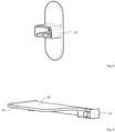
- FIGS. 8 and 9 Two embodiments of holders 21 for the solid soap dispenser 1 are shown.
- the first in Figure 8 The embodiment of a bracket 21 shown is a simple bracket 21 with two projecting semicircular surfaces towards the respective end, which can be mounted on a wall using appropriate mounting means, for example screws and dowels.
- Figure 9 The holder 21 shown also has a storage surface 22 on which, in particular, drugstore or cosmetic articles can be placed.
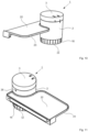
- Figures 10 and 11 show the combination of the bracket 21 according to Figure 9 with the solid soap dispenser according to the Figures 1 to 5 both in a perspective view from the front and from the rear. Since the solid soap dispenser 1 can also be used in wet rooms, the storage surface 22 has a splash rim 23.
Landscapes
- Health & Medical Sciences (AREA)
- Public Health (AREA)
- Containers And Packaging Bodies Having A Special Means To Remove Contents (AREA)
- Closures For Containers (AREA)
Priority Applications (2)
| Application Number | Priority Date | Filing Date | Title |
|---|---|---|---|
| EP23215608.3A EP4570151B1 (fr) | 2023-12-11 | 2023-12-11 | Distributeur de savon solide |
| US18/976,531 US20250185855A1 (en) | 2023-12-11 | 2024-12-11 | Solid soap dispenser |
Applications Claiming Priority (1)
| Application Number | Priority Date | Filing Date | Title |
|---|---|---|---|
| EP23215608.3A EP4570151B1 (fr) | 2023-12-11 | 2023-12-11 | Distributeur de savon solide |
Publications (3)
| Publication Number | Publication Date |
|---|---|
| EP4570151A1 true EP4570151A1 (fr) | 2025-06-18 |
| EP4570151B1 EP4570151B1 (fr) | 2026-02-25 |
| EP4570151C0 EP4570151C0 (fr) | 2026-02-25 |
Family
ID=89168181
Family Applications (1)
| Application Number | Title | Priority Date | Filing Date |
|---|---|---|---|
| EP23215608.3A Active EP4570151B1 (fr) | 2023-12-11 | 2023-12-11 | Distributeur de savon solide |
Country Status (2)
| Country | Link |
|---|---|
| US (1) | US20250185855A1 (fr) |
| EP (1) | EP4570151B1 (fr) |
Citations (4)
| Publication number | Priority date | Publication date | Assignee | Title |
|---|---|---|---|---|
| GB658448A (en) * | 1948-05-14 | 1951-10-10 | Ernst Ritter | A soap distributor |
| CH379716A (fr) * | 1962-10-06 | 1964-07-15 | Steiner Co Lausanne Sa | Distributeur de savon en poudre |
| DE202021003799U1 (de) * | 2021-12-16 | 2022-02-16 | Meerkorn Gmbh | Mobiler Seifenspender für feste Stückseife |
| DE102022116669B3 (de) * | 2022-07-04 | 2023-10-26 | Manuel Kroll | Seifenspender für Festkörperseife und Festkörperseife |
-
2023
- 2023-12-11 EP EP23215608.3A patent/EP4570151B1/fr active Active
-
2024
- 2024-12-11 US US18/976,531 patent/US20250185855A1/en active Pending
Patent Citations (4)
| Publication number | Priority date | Publication date | Assignee | Title |
|---|---|---|---|---|
| GB658448A (en) * | 1948-05-14 | 1951-10-10 | Ernst Ritter | A soap distributor |
| CH379716A (fr) * | 1962-10-06 | 1964-07-15 | Steiner Co Lausanne Sa | Distributeur de savon en poudre |
| DE202021003799U1 (de) * | 2021-12-16 | 2022-02-16 | Meerkorn Gmbh | Mobiler Seifenspender für feste Stückseife |
| DE102022116669B3 (de) * | 2022-07-04 | 2023-10-26 | Manuel Kroll | Seifenspender für Festkörperseife und Festkörperseife |
Also Published As
| Publication number | Publication date |
|---|---|
| US20250185855A1 (en) | 2025-06-12 |
| EP4570151B1 (fr) | 2026-02-25 |
| EP4570151C0 (fr) | 2026-02-25 |
Similar Documents
| Publication | Publication Date | Title |
|---|---|---|
| DE19628172B4 (de) | Spender für Flüssigkeiten, insbesondere Flüssigseife | |
| DE60212066T2 (de) | Abgabespritze | |
| EP2226437B1 (fr) | Chasse d'eau et procédé d'introduction d'un additif dans une telle chasse d'eau | |
| EP0853458B1 (fr) | Distributeur-doseur de liquides | |
| EP3525642B1 (fr) | Dispositif recevant un récipient pour récipient distributeur | |
| DE1994469U (de) | Vorrichtung zum ausgeben fliessfaehiger substanzen. | |
| DE3714018A1 (de) | Abgabevorrichtung fuer fluessigkeiten | |
| EP0606879B1 (fr) | Dispositif avec une poubelle, un couvercle et un mécanisme d'ouverture du couvercle pour usage domestique et installations sanitaires | |
| DE9312110U1 (de) | Behälter für fließfähige Medien | |
| DE102012110521B4 (de) | Lebensmittelhacker | |
| EP4570151B1 (fr) | Distributeur de savon solide | |
| DE69308423T2 (de) | Tablettenspender | |
| DE102015100201A1 (de) | Dosierspender | |
| DE1978764U (de) | Vorrichtung zur verhuetung einer verunreinigung der luft in toiletten, badezimmern und aehnlichen raeumen. | |
| DE9312397U1 (de) | Spender für flüssiges Desinfektionsmittel, Tensidprodukte u.dgl. | |
| DE29511897U1 (de) | Spender für Kosmetika wie Duschgel, Shampoo, Seifen o.dgl. | |
| DE10331786B4 (de) | Spender für flüssige oder pastenförmige Medien | |
| DE3924179A1 (de) | Sanitaeranlage | |
| DE2559761A1 (de) | Fluessigkeitsspender | |
| DE102021126809A1 (de) | Wanddosierspender | |
| DE4107992B4 (de) | Seifenspender | |
| DE29700945U1 (de) | Wasserauslaufarmatur mit integriertem Waschmittelspender | |
| CH699581A2 (de) | Vorrichtung mit einem Griff. | |
| DE10042401C2 (de) | Spendervorrichtung für Flüssigkeiten | |
| DE202023002847U1 (de) | Dosiervorrichtung |
Legal Events
| Date | Code | Title | Description |
|---|---|---|---|
| PUAI | Public reference made under article 153(3) epc to a published international application that has entered the european phase |
Free format text: ORIGINAL CODE: 0009012 |
|
| STAA | Information on the status of an ep patent application or granted ep patent |
Free format text: STATUS: REQUEST FOR EXAMINATION WAS MADE |
|
| 17P | Request for examination filed |
Effective date: 20240611 |
|
| AK | Designated contracting states |
Kind code of ref document: A1 Designated state(s): AL AT BE BG CH CY CZ DE DK EE ES FI FR GB GR HR HU IE IS IT LI LT LU LV MC ME MK MT NL NO PL PT RO RS SE SI SK SM TR |
|
| GRAP | Despatch of communication of intention to grant a patent |
Free format text: ORIGINAL CODE: EPIDOSNIGR1 |
|
| STAA | Information on the status of an ep patent application or granted ep patent |
Free format text: STATUS: GRANT OF PATENT IS INTENDED |
|
| INTG | Intention to grant announced |
Effective date: 20251125 |
|
| GRAS | Grant fee paid |
Free format text: ORIGINAL CODE: EPIDOSNIGR3 |
|
| GRAA | (expected) grant |
Free format text: ORIGINAL CODE: 0009210 |
|
| STAA | Information on the status of an ep patent application or granted ep patent |
Free format text: STATUS: THE PATENT HAS BEEN GRANTED |
|
| AK | Designated contracting states |
Kind code of ref document: B1 Designated state(s): AL AT BE BG CH CY CZ DE DK EE ES FI FR GB GR HR HU IE IS IT LI LT LU LV MC ME MK MT NL NO PL PT RO RS SE SI SK SM TR |
|
| REG | Reference to a national code |
Ref country code: CH Ref legal event code: F10 Free format text: ST27 STATUS EVENT CODE: U-0-0-F10-F00 (AS PROVIDED BY THE NATIONAL OFFICE) Effective date: 20260225 Ref country code: GB Ref legal event code: FG4D Free format text: NOT ENGLISH |
|
| REG | Reference to a national code |
Ref country code: CH Ref legal event code: R17 Free format text: ST27 STATUS EVENT CODE: U-0-0-R10-R17 (AS PROVIDED BY THE NATIONAL OFFICE) Effective date: 20260304 |
|
| REG | Reference to a national code |
Ref country code: DE Ref legal event code: R096 Ref document number: 502023003155 Country of ref document: DE |
|
| REG | Reference to a national code |
Ref country code: IE Ref legal event code: FG4D Free format text: LANGUAGE OF EP DOCUMENT: GERMAN |
|
| U01 | Request for unitary effect filed |
Effective date: 20260303 |
|
| U07 | Unitary effect registered |
Designated state(s): AT BE BG DE DK EE FI FR IT LT LU LV MT NL PT RO SE SI Effective date: 20260311 |