EP4570164A2 - Dispositif d'observation et procédé d'observation d'un oeil - Google Patents
Dispositif d'observation et procédé d'observation d'un oeil Download PDFInfo
- Publication number
- EP4570164A2 EP4570164A2 EP24215490.4A EP24215490A EP4570164A2 EP 4570164 A2 EP4570164 A2 EP 4570164A2 EP 24215490 A EP24215490 A EP 24215490A EP 4570164 A2 EP4570164 A2 EP 4570164A2
- Authority
- EP
- European Patent Office
- Prior art keywords
- unit
- positioning
- beam path
- tube
- microscope
- Prior art date
- Legal status (The legal status is an assumption and is not a legal conclusion. Google has not performed a legal analysis and makes no representation as to the accuracy of the status listed.)
- Pending
Links
Images




Classifications
-
- A—HUMAN NECESSITIES
- A61—MEDICAL OR VETERINARY SCIENCE; HYGIENE
- A61B—DIAGNOSIS; SURGERY; IDENTIFICATION
- A61B3/00—Apparatus for testing the eyes; Instruments for examining the eyes
- A61B3/10—Objective types, i.e. instruments for examining the eyes independent of the patients' perceptions or reactions
- A61B3/13—Ophthalmic microscopes
-
- A—HUMAN NECESSITIES
- A61—MEDICAL OR VETERINARY SCIENCE; HYGIENE
- A61B—DIAGNOSIS; SURGERY; IDENTIFICATION
- A61B3/00—Apparatus for testing the eyes; Instruments for examining the eyes
- A61B3/0075—Apparatus for testing the eyes; Instruments for examining the eyes provided with adjusting devices, e.g. operated by control lever
-
- A—HUMAN NECESSITIES
- A61—MEDICAL OR VETERINARY SCIENCE; HYGIENE
- A61B—DIAGNOSIS; SURGERY; IDENTIFICATION
- A61B3/00—Apparatus for testing the eyes; Instruments for examining the eyes
- A61B3/10—Objective types, i.e. instruments for examining the eyes independent of the patients' perceptions or reactions
- A61B3/12—Objective types, i.e. instruments for examining the eyes independent of the patients' perceptions or reactions for looking at the eye fundus, e.g. ophthalmoscopes
-
- A—HUMAN NECESSITIES
- A61—MEDICAL OR VETERINARY SCIENCE; HYGIENE
- A61B—DIAGNOSIS; SURGERY; IDENTIFICATION
- A61B46/00—Surgical drapes
- A61B46/10—Surgical drapes specially adapted for instruments, e.g. microscopes
-
- A—HUMAN NECESSITIES
- A61—MEDICAL OR VETERINARY SCIENCE; HYGIENE
- A61B—DIAGNOSIS; SURGERY; IDENTIFICATION
- A61B90/00—Instruments, implements or accessories specially adapted for surgery or diagnosis and not covered by any of the groups A61B1/00 - A61B50/00, e.g. for luxation treatment or for protecting wound edges
-
- A—HUMAN NECESSITIES
- A61—MEDICAL OR VETERINARY SCIENCE; HYGIENE
- A61B—DIAGNOSIS; SURGERY; IDENTIFICATION
- A61B90/00—Instruments, implements or accessories specially adapted for surgery or diagnosis and not covered by any of the groups A61B1/00 - A61B50/00, e.g. for luxation treatment or for protecting wound edges
- A61B90/10—Instruments, implements or accessories specially adapted for surgery or diagnosis and not covered by any of the groups A61B1/00 - A61B50/00, e.g. for luxation treatment or for protecting wound edges for stereotaxic surgery, e.g. frame-based stereotaxis
-
- A—HUMAN NECESSITIES
- A61—MEDICAL OR VETERINARY SCIENCE; HYGIENE
- A61B—DIAGNOSIS; SURGERY; IDENTIFICATION
- A61B90/00—Instruments, implements or accessories specially adapted for surgery or diagnosis and not covered by any of the groups A61B1/00 - A61B50/00, e.g. for luxation treatment or for protecting wound edges
- A61B90/20—Surgical microscopes characterised by non-optical aspects
-
- A—HUMAN NECESSITIES
- A61—MEDICAL OR VETERINARY SCIENCE; HYGIENE
- A61B—DIAGNOSIS; SURGERY; IDENTIFICATION
- A61B90/00—Instruments, implements or accessories specially adapted for surgery or diagnosis and not covered by any of the groups A61B1/00 - A61B50/00, e.g. for luxation treatment or for protecting wound edges
- A61B90/50—Supports for surgical instruments, e.g. articulated arms
-
- A—HUMAN NECESSITIES
- A61—MEDICAL OR VETERINARY SCIENCE; HYGIENE
- A61F—FILTERS IMPLANTABLE INTO BLOOD VESSELS; PROSTHESES; DEVICES PROVIDING PATENCY TO, OR PREVENTING COLLAPSING OF, TUBULAR STRUCTURES OF THE BODY, e.g. STENTS; ORTHOPAEDIC, NURSING OR CONTRACEPTIVE DEVICES; FOMENTATION; TREATMENT OR PROTECTION OF EYES OR EARS; BANDAGES, DRESSINGS OR ABSORBENT PADS; FIRST-AID KITS
- A61F9/00—Methods or devices for treatment of the eyes; Devices for putting in contact-lenses; Devices to correct squinting; Apparatus to guide the blind; Protective devices for the eyes, carried on the body or in the hand
- A61F9/007—Methods or devices for eye surgery
-
- G—PHYSICS
- G02—OPTICS
- G02B—OPTICAL ELEMENTS, SYSTEMS OR APPARATUS
- G02B21/00—Microscopes
- G02B21/0004—Microscopes specially adapted for specific applications
- G02B21/0012—Surgical microscopes
-
- G—PHYSICS
- G02—OPTICS
- G02B—OPTICAL ELEMENTS, SYSTEMS OR APPARATUS
- G02B21/00—Microscopes
- G02B21/24—Base structure
-
- G—PHYSICS
- G02—OPTICS
- G02B—OPTICAL ELEMENTS, SYSTEMS OR APPARATUS
- G02B21/00—Microscopes
- G02B21/24—Base structure
- G02B21/241—Devices for focusing
-
- G—PHYSICS
- G02—OPTICS
- G02B—OPTICAL ELEMENTS, SYSTEMS OR APPARATUS
- G02B21/00—Microscopes
- G02B21/24—Base structure
- G02B21/248—Base structure objective (or ocular) turrets
-
- G—PHYSICS
- G02—OPTICS
- G02B—OPTICAL ELEMENTS, SYSTEMS OR APPARATUS
- G02B21/00—Microscopes
- G02B21/24—Base structure
- G02B21/26—Stages; Adjusting means therefor
-
- G—PHYSICS
- G02—OPTICS
- G02B—OPTICAL ELEMENTS, SYSTEMS OR APPARATUS
- G02B7/00—Mountings, adjusting means, or light-tight connections, for optical elements
- G02B7/001—Counterbalanced structures, e.g. surgical microscopes
-
- G—PHYSICS
- G02—OPTICS
- G02B—OPTICAL ELEMENTS, SYSTEMS OR APPARATUS
- G02B7/00—Mountings, adjusting means, or light-tight connections, for optical elements
- G02B7/02—Mountings, adjusting means, or light-tight connections, for optical elements for lenses
-
- G—PHYSICS
- G02—OPTICS
- G02B—OPTICAL ELEMENTS, SYSTEMS OR APPARATUS
- G02B7/00—Mountings, adjusting means, or light-tight connections, for optical elements
- G02B7/02—Mountings, adjusting means, or light-tight connections, for optical elements for lenses
- G02B7/021—Mountings, adjusting means, or light-tight connections, for optical elements for lenses for more than one lens
-
- G—PHYSICS
- G02—OPTICS
- G02B—OPTICAL ELEMENTS, SYSTEMS OR APPARATUS
- G02B7/00—Mountings, adjusting means, or light-tight connections, for optical elements
- G02B7/02—Mountings, adjusting means, or light-tight connections, for optical elements for lenses
- G02B7/023—Mountings, adjusting means, or light-tight connections, for optical elements for lenses permitting adjustment
-
- A—HUMAN NECESSITIES
- A61—MEDICAL OR VETERINARY SCIENCE; HYGIENE
- A61B—DIAGNOSIS; SURGERY; IDENTIFICATION
- A61B90/00—Instruments, implements or accessories specially adapted for surgery or diagnosis and not covered by any of the groups A61B1/00 - A61B50/00, e.g. for luxation treatment or for protecting wound edges
- A61B90/03—Automatic limiting or abutting means, e.g. for safety
- A61B2090/037—Automatic limiting or abutting means, e.g. for safety with a frangible part, e.g. by reduced diameter
-
- A—HUMAN NECESSITIES
- A61—MEDICAL OR VETERINARY SCIENCE; HYGIENE
- A61B—DIAGNOSIS; SURGERY; IDENTIFICATION
- A61B90/00—Instruments, implements or accessories specially adapted for surgery or diagnosis and not covered by any of the groups A61B1/00 - A61B50/00, e.g. for luxation treatment or for protecting wound edges
- A61B90/08—Accessories or related features not otherwise provided for
- A61B2090/0813—Accessories designed for easy sterilising, i.e. re-usable
-
- A—HUMAN NECESSITIES
- A61—MEDICAL OR VETERINARY SCIENCE; HYGIENE
- A61B—DIAGNOSIS; SURGERY; IDENTIFICATION
- A61B90/00—Instruments, implements or accessories specially adapted for surgery or diagnosis and not covered by any of the groups A61B1/00 - A61B50/00, e.g. for luxation treatment or for protecting wound edges
- A61B90/08—Accessories or related features not otherwise provided for
- A61B2090/0814—Preventing re-use
Definitions
- the invention relates to an observation device with a positioning unit for positioning an optical unit in a beam path of a microscope between an objective of the microscope and in front of an eye to be observed, wherein the positioning unit comprises a connecting device, a positioning device, a receiving device and the optical unit, wherein the optical unit comprises a lens which serves to observe an ocular fundus and a further optical element, wherein the positioning unit comprises a pivoting device by means of which the optical unit can be pivoted out of or into the beam path, wherein the positioning unit can be coupled to the microscope by means of the connecting device, wherein the lens is adapted to the positioning device by means of the receiving device. Furthermore, the invention relates to a method for observing an eye using such an observation device.
- Microscopes for performing eye surgery are regularly used for operations in the front part of the eye. If such procedures are to be performed in the back part of the eye, it is necessary to equip the microscope with an observation device. to be supplemented, which enables focusing of precisely this area of the eye.
- observation devices comprise at least one wide-angle lens or ophthalmoscopy lens for wide-angle viewing of the relevant posterior part of the eye, wherein the ophthalmoscopy lens provides an intermediate image in a beam path in front of a microscope objective, which can be focused with the microscope. Focusing the intermediate image requires shortening the length of the microscope beam path, which can be done using the corresponding adjustment device on the microscope.
- the two lenses are held as an optical unit by a positioning unit of the observation device, which is attached directly to the microscope. They can be positioned in the beam path as needed without requiring any significant adjustment of the microscope during surgery.
- the positioning unit usually includes a connecting device by means of which the positioning unit can be coupled to the microscope. Furthermore, the positioning unit is designed so that the respective lenses can be easily pivoted or inserted into the beam path and removed from it again.
- Such an observation device is known, for example, from DE 10 2011 002 940 A1 known.
- the ophthalmoscope lens is designed to be adjustable along the beam path of the microscope using a screw drive.
- This observation device is designed so that the ophthalmoscope lens can be adjusted relative to the eye along the beam path. It is advantageous if the ophthalmoscope lens is positioned as close to the eye as possible, as this allows a comparatively large area of the eye to be clearly visible. At the same time, however, contact between the ophthalmoscope lens and the eye must be avoided. In order to obtain a sharp image of the largest possible area of the eye, it is therefore always necessary to vary the distance of the microscope relative to the eye and to coordinate this with the distance of the ophthalmoscope lens.
- observation devices made of plastic are known that allow for a single use of the observation device.
- DE 10 2018 127 469 B4 shows such an observation device.
- the disadvantage here is that plastic, in contrast to metal, cannot always be used with the desired accuracy required for the ophthalmoscopic lens to be positioned, especially when the positioning device or the positioning unit is made of fragile plastic struts. This can easily lead to a displacement of the ophthalmoscopic lens along the beam path or an offset transverse to it when the ophthalmoscopic lens is pivoted into or out of the beam path. This then requires regular correction of the position of the ophthalmoscopy lens, which is an obstacle to performing eye surgery.
- the present invention is therefore based on the object of proposing an observation device and a method for observing an eye, which enables improved handling during an eye operation.
- the positioning unit comprises a connecting device, a positioning device, a receiving device and the optical unit, wherein the optical unit comprises a lens which serves to observe an ocular fundus and a further optical element, wherein the positioning unit comprises a pivoting device by means of which the optical unit can be pivoted out of or into the beam path, wherein the positioning unit can be coupled to the microscope by means of the connecting device, wherein the lens is adapted to the positioning unit by means of the receiving device, wherein the further optical element is arranged below the pivoting device, wherein the further optical element can be moved relative to the microscope in the longitudinal direction of the beam path by means of the positioning device.
- the observation device can be adapted to a microscope or detachably connected to it by means of the connecting device.
- the lens which can be an ophthalmoscope lens, is then inserted into the beam path of the objective is held between the eye to be observed and the objective.
- the lens is to be arranged in such a way that a main axis or optical axis of the objective of the microscope runs through a center point of the lens.
- the optical unit with the lens and the further optical element which is preferably a lens with positive refractive power, can be pivoted into the beam path or out again as required during an eye operation.
- the pivoting device can therefore also be understood as a displacement device by means of which the optical unit can be moved parallel to the beam path.
- the movable arrangement of the additional optical element below the pivoting device makes it possible to adapt the beam path of the microscope or to shorten this beam path to such an extent that an intermediate image of the lens can be focused. Since the additional optical element below the pivoting device is movable along the beam path, comparatively more space is available for moving the additional optical element along the beam path than if the additional optical element were arranged above the pivoting device.
- the distance between the pivoting device and the microscope objective is comparatively short, as this is the only way to ensure complete removal of the optical unit or positioning device from the beam path.
- the comparatively larger adjustment range of the additional optical element allows the observation device to be universally adapted to different microscope types and thus used for them.
- the positioning device can have a tube that is pivotably mounted on the pivoting mechanism. This advantageously enables the arrangement of the additional optical element within the tube. A movable arrangement of the additional optical element within the tube is particularly easy. The additional optical element can also be easily protected from external influences.
- the lens can be an ophthalmoscopy lens, wherein the further optical element can be at least one lens with positive refractive power, which serves to adjust the beam path, wherein the lens can be arranged in the tube below the pivoting device so as to be movable in the longitudinal direction of the beam path.
- the lens with positive refractive power can be a so-called reducing lens, by means of which the beam path of the microscope can be shortened. Because the lens with positive refractive power is movable in the tube below the pivoting device along the beam path, the beam path can be easily adjusted over a comparatively large adjustment range.
- the displacement of the lens with positive refractive power along the beam path can be easily achieved by means of a screw drive, a helix formed within the tube, or the like. In this case, it can be provided that the tube is at least partially rotated.
- the lens with positive refractive power can be mounted in a mount which can be moved together with the lens within the tube.
- the positioning device can have a drive unit by means of which a position of the further optical element can be adjusted in the longitudinal direction of the beam path.
- the drive unit can be operated purely manually or electrically. It is essential that the further optical element can be displaced and positioned along the beam path by means of the drive unit. In this respect, it is also advantageous if the drive unit is designed to be self-locking. If the further optical element is arranged within the tube, the drive unit can also be formed, at least partially or entirely, on the tube.
- the drive unit can be arranged on the connecting device above the pivoting device and/or below the pivoting device on the tube. Accordingly, the drive unit can be arranged solely on the tube or can be configured so that the drive unit is arranged on the connecting device and the tube. Depending on the design of the drive unit, it may be advantageous to arrange only part of the drive unit on the tube, so that the surgeon is not hindered in his work by protruding components of the observation device.
- the drive unit can comprise a stepper motor, which can be coupled to the tube via a belt drive or a gear to a coupling of the drive unit.
- the stepper motor can then be an electric motor, with which a defined number of revolutions can be carried out until the further optical element is located at the desired position of the tube.
- the tube can be designed to be rotatable in sections, so that revolutions of the stepper motor can be transmitted to the tube via the belt drive and/or a gear.
- the drive unit can, for example, comprise a sleeve within the tube, which is provided with a thread or a A coil is formed and is connected to the belt drive and/or the gearbox via the coupling. Rotation of the sleeve, which can be moved by the stepper motor, can then raise or lower the additional optical element or move it along the beam path.
- the coupling can be separable or connectable by means of the pivoting device. This is particularly advantageous when the stepper motor with the belt drive or the gear is arranged above the pivoting device on the connecting device.
- the coupling can then be configured between the connecting device and the tube in such a way that the coupling is separated when the tube is pivoted out of the beam path, and the coupling is connected when the tube is pivoted into the beam path.
- the coupling can be configured as a force-fit, form-fit, and/or friction-fit coupling.
- the coupling is a magnetic coupling formed from two rings that can transmit torque by means of magnets, whereby the other optical element can be moved by rotation of the tube.
- the two coaxial rings can each have a number of magnets that exert a magnetic force on one another such that the rings attract one another and the torque can thus be transmitted.
- the magnets can be arranged at a uniform distance on an axial end face of the respective rings.
- the poles of the magnets of the respective rings can alternate so that the rings are in a defined relative position when the coupling is closed. It is particularly advantageous if a gap is formed between the rings, since then the rings or the coupling do not have to lie against one another to transmit the torque.
- the gap can be used to insert a sterile cover into the coupling or between the tube and the connecting device.
- the positioning unit can comprise a control device, wherein the control device can be designed to detect an optical unit pivoting out of or into the beam path and transmit this information to the microscope.
- the detection of the pivoting out or in of the optical unit or tube can easily be done using a sensor of the control device.
- the control device can then signal to the microscope whether the optical unit has pivoted into or out of the beam path. If the microscope is equipped with a so-called inverter, the microscope can move the inverter into or out of the beam path within the microscope.
- the inverter can then generate a beam exchange and a mirror image of the intermediate image of the lens, so that a surgeon is presented with a correctly positioned image of the eye when the optical unit is pivoted into the beam path.
- the positioning unit can comprise a control device, wherein a rotation of the tube can be detected by means of a sensor of the control device, wherein the drive unit can be controlled by means of the control device such that the further optical element can be moved to a predefined position in the longitudinal direction of the beam path by means of the drive unit.
- the sensor can, for example, be a Hall sensor arranged on the drive unit or the tube. A mark, a number of marks in the form of a scale or the like, can be arranged on the tube, so that a rotation and position of the further optical element in the longitudinal direction of the beam path can be detected by means of the sensor. This then makes it possible to detect a position of the further optical element along an adjustment range.
- the control device can now use the drive unit to move the optical element to the required position or the previously set focus of the optical unit. It is then no longer necessary for the surgeon to operate the drive unit to correct a changed setting of the other optical element.
- the receiving device can be designed with a further, preferably conical tube.
- the further tube can be directly connected to the tube and firmly connected to it.
- the fixed connection can be formed, for example, by a snap-in connection.
- the further tube is designed in the manner of a cone.
- the tube can then be adapted to the course of a beam path in such a way that a diameter of the further tube at a lower end of the further tube is comparatively small.
- the lens can then be arranged at the lower end.
- the further tube is designed to be closed.
- the further tube can then be designed in the manner of a conical sleeve.
- the further tube can be formed from an upper section and a lower section, whereby the lower section can be mounted loosely or spring-loaded on the upper section, such that the lower section can be pushed into the upper section.
- the spring-loaded mounting can be formed by a compression spring that is inserted into the upper section, and against whose spring force the lower section can be moved into the upper section. This can prevent unwanted eye injury in the event of a collision between the lens or the lower section and the eye of a person undergoing surgery.
- At least one manually operable projection may be formed on the lower portion, wherein the projection has a recess in the upper section and can be moved along the longitudinal slot.
- a surgeon can then manually move the lower section in the direction of the beam path by grasping the projection and pulling it upwards towards the microscope in such a way that the lower section is moved into the upper section.
- two opposing projections can also be formed on the lower section for this purpose, which engage in mutually opposite longitudinal slots on the upper section.
- the option of manually moving the lower section in the direction of the beam path away from the eye can be advantageously used by a surgeon if the optical unit is to be pivoted out of the beam path.
- the lens can be manually moved out of a danger zone for the eye and, in an immediately following manual movement, the optical unit can be pivoted out of the beam path.
- the observation device can comprise a shielding unit for shielding an optical path of the positioning unit, wherein the shielding unit can be formed from at least one optically shielded or closed tube.
- the positioning device and the receiving device can, for example, form this closed tube. This advantageously prevents light sources used during eye surgery, stray light, or the like from entering the beam path and undesirably influencing the representation of the image of the eye, which is observed by a surgeon through the optical unit. Possible differences in brightness, reflections, or the like can thus be avoided.
- the receiving device can be made, at least predominantly, preferably entirely, of plastic material, wherein the positioning device can have a tube that is pivotably arranged on the pivoting device, wherein the tube can be made at least predominantly or entirely of metal.
- the receiving device that holds the lens can be made essentially of plastic material and the tube essentially of metal.
- the pivotable tube can then be designed to be particularly stable and precise and enables exact positioning of the lens and the other optical element in the beam path without the need for corrective adjustment, as is the case with purely disposable products.
- the receiving device is made of plastic, it is then possible to manufacture the receiving device with the lens particularly cost-effectively. Production can be carried out easily and in large quantities, for example, using an injection molding process.
- the receiving device to be used as a disposable product.
- the receiving device can then be disposed of after an eye operation. Sterilization of the receiving device is not necessary.
- a new receptacle which can be packaged sterile, can be used.
- the receptacle can be easily adapted to the tube or detachably connected to it.
- the observation device can comprise a cover unit made of plastic material for sterile covering of the pivoting tube of the positioning device.
- the cover unit can be designed with comparatively thin walls so that the cover unit can lie tightly against the pivoting tube.
- the plastic material can be rigid or flexible.
- the plastic material can be opaque or optically partially transparent.
- the cover unit can be designed such that the The outer surface of the pivoting tube is completely shielded from the environment by the cover unit.
- the pivoting tube can then be manually grasped and operated by a surgeon, even without the need for subsequent sterilization of the tube. It is then only necessary to remove the cover unit, which can be manufactured inexpensively from plastic material, and replace it with a new, previously unused, sterile cover unit.
- the cover unit can have an upper sterile cover for at least partially covering an end face of the tube and a lower sterile cover for at least partially covering a peripheral surface of the tube. Accordingly, the cover unit can be designed in at least two parts.
- the upper sterile cover can be placed onto the end face of the tube from above when the tube is pivoted out of the beam path.
- the lower sterile cover can be plugged onto the tube from below.
- the tube is then surrounded on all sides by the cover unit.
- the upper sterile cover protects the end face of the tube from contact by the surgeon when they manually grasp the tube in a position pivoted out of the beam path. If an upper sterile cover is used, it is also advantageous if a gap is formed between the tube and the connecting device, within which gap the upper sterile cover can be located when the tube is pivoted into the beam path.
- the cover unit can be formed with at least one connecting element, which requires the connecting element to be destroyed when the cover unit is separated from the positioning device.
- the connecting element can be designed as a locking element that engages over a projection formed on the tube or engages in a groove formed on the tube.
- a plurality of connecting elements can also be provided.
- the connecting element can be designed or mounted flexibly so that the connecting element can easily fit against the tube. It is essential that the connecting element is designed in such a way that if the cover unit is removed from the positioning device or the tube, the connecting element or the cover unit is destroyed. This can prevent the cover unit from being accidentally reused.
- the cover unit can have at least one tear strip, by means of which the cover unit can be at least partially destroyed.
- the tear strip can be formed with a tab that can be easily grasped manually.
- the tear strip can be formed by one weakening line or two parallel weakening lines in the cover unit. If the cover unit is attached to the positioning device or the tube, for example, by means of a snap-in connection, the snap-in connection can be destroyed by manually actuating the tear strip. This makes it possible to easily remove the cover unit from the positioning device or the tube.
- the receiving device can be configured with at least one connecting element, which requires the connecting element to be destroyed when the receiving device is separated from the positioning device. This can also prevent the receiving device from being accidentally recycled after being separated from the positioning device.
- the connecting element can, for example, be configured such that the connecting element breaks when the receiving device is removed from the positioning device.
- the microscope according to the invention comprises an observation device according to the invention. Further advantageous embodiments of the microscope emerge from the feature descriptions of the subclaims referring back to claim 1.
- an optical unit is positioned in a beam path of a microscope between an objective of the microscope and in front of an eye to be observed by means of a positioning unit of the observation device.
- the positioning unit comprises a connecting device, a positioning device, a receiving device, and the optical unit.
- the optical unit comprises a lens used to observe an ocular fundus and a further optical element.
- the positioning unit comprises a pivoting device by means of which the optical unit is pivoted out of or into the beam path.
- the positioning unit is coupled to the microscope by means of the connecting device.
- the lens is adapted to the positioning unit by means of the receiving device.
- the further optical element is arranged below the pivoting device. The further optical element is moved relative to the microscope in the longitudinal direction of the beam path by means of the positioning device.
- the additional optical element can be used to correct refractive errors of the eye. Since the additional optical element enables focusing of an intermediate image of the lens, thus adjusting the microscope's beam path, a refractive error of the eye can also be corrected with the additional optical element.
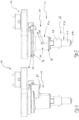
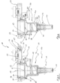
- FIG. 1 to 8 shows an observation device 10 with a positioning unit 11 for positioning an optical unit 12 in a beam path 13 of a microscope (not shown in detail here).
- the observation device 10 is arranged between an objective lens of the microscope and in front of an eye to be observed on the Microscope adaptable.
- the positioning unit 11 comprises a connecting device 14, a positioning device 15, a receiving device 16 and the optical unit 12.
- the optical unit 12 is formed by an ophthalmoscopic lens 17 and a lens with positive refractive power or reducing lens 18.
- the ophthalmoscopic lens 17 is used here for observing the fundus of the eye, and the reducing lens 18 is used to adapt the beam path 13 of the microscope to an intermediate image of the ophthalmoscopic lens 17 (not visible here).
- the positioning unit 11 comprises a pivoting device 19 by means of which the optical unit 12 can be pivoted into or out of the beam path 13.
- the Fig. 1 to 3 , 5 and 6 show the positioning device 15 pivoted into the beam path 13 with the optical unit 12 and the Fig. 4 , 7 and 8 , the positioning device 15 pivoted out of the beam path 13 with the optical unit 12.
- the positioning unit 11 can be coupled to a microscope by means of the connecting device 14.
- the connecting device 14 is formed here, among other things, by a receptacle 20 with a rail 21 and clamping screw 22 and can be adapted to an objective of the microscope such that the objective directly adjoins an upper side 23 of the connecting device 14.
- the receiving device 16 is made almost entirely of plastic and holds the ophthalmoscopy lens 17.
- the receiving device 16 is adapted to the positioning device 15.
- the positioning device 15 is made essentially of metal.
- a tube 24 of the positioning device 15 can be pivoted by means of the pivoting device 19, which is formed here by a hinge 25, from a substantially vertical position in the beam path 13 out of the beam path 13 by more than 90 degrees so that the beam path 13 is released.
- the hinge 25 is formed with a guide 26, which enables the positioning device 15 to be locked into the respective in the Fig. 2 and 4 shown positions. The positioning device 15 can thus be securely fixed in the respective position.
- the receiving device 16 is formed by a further tube 27, which here is formed from an upper section 28 and a lower section 29. Furthermore, a compression spring 30 is inserted into the upper section 28 and fixed in the upper section 29 by means of a ring 31. The ophthalmoscopy lens 17 is held at a lower end 32 of the receiving device 16. Furthermore, the lower section 29 is formed with two projections 33, each of which extends through a longitudinal slot 34 in the upper section 28. The compression spring 30 bears against an upper edge 35 of the lower section 29, with the lower section 29 resting with an annular shoulder 36 on a shoulder 37 at a lower end 38 of the upper section 28.
- the lower section 29 can now be pushed into the upper section 28 against a spring force of the compression spring 30. Furthermore, it is also possible to grasp the projections 33 with one hand and to push the lower section 29 into the upper section 28 in order to create a sufficient distance from an eye when the receiving device 16 is to be pivoted together with the positioning device 15.
- the receiving device 16 is formed with connecting elements 39 that engage and lock into a groove 40 within the tube 40.
- the connecting elements 39 are formed on tabs 41 at an upper end 42 of the upper section 28.
- the tabs 41 allow for resilient mounting of the connecting elements 39 transversely to the beam path 13 and can also be manually actuated. Compressing or pronating the tabs 41 then allows the receiving device 16 to be removed from the tube 24.
- the tube 24 is essentially formed from an outer sleeve 43 and an inner sleeve 44, wherein the inner sleeve 44 is rotatably mounted on a bearing 45 within the tube 24.
- a mount 46 with the reducing lens 18 is inserted into the inner sleeve 44.
- a helix 47 is formed in the inner sleeve 44 and a slot 48 is formed in the outer sleeve 43.
- Opposing projections 49 on the mount 46 each pass through the helixes 47 and the slots 48. Rotation of the inner sleeve 44 relative to the outer sleeve 43 thus causes the mount 46 with the reducing lens 18 to move along the beam path 13.
- the position of the reducing lens 18 in the tube 24 is visible to a user on a circumferential surface 50 of the tube 24.
- the projections 49 in the slots 48 are visible.
- the ophthalmoscopy lens 17 can first be aligned with the eye by adjusting the height of the microscope. Subsequently, the reducing lens 18 can be adjusted by adjusting its position in the tube 24 so that an intermediate image of the ophthalmoscopy lens 17 can be sharply focused with the microscope.
- the rotation of the inner sleeve 44 in the outer sleeve 43 is carried out by a drive unit 51 of the positioning device 15.
- the drive unit 51 is arranged here on the connecting device 14 and comprises a stepper motor 52, a belt drive 53, and a coupling 54.
- a drive wheel 55 of the belt drive 53 is connected here via a belt 56 to an output sleeve 57 within the connecting device 14.
- the output sleeve 57 coaxially surrounds the beam path 13 and is rotatably mounted in a housing 59 of the connecting device 14 by means of a bearing 58.
- the coupling 54 is designed as a magnetic coupling 60, wherein magnets 63 are embedded in an axial end face 61 of the inner sleeve 44 and in an opposite axial end face 62 of the output sleeve 57.
- the magnets 63 are arranged with alternating polarity such that opposing magnets 63 exert a magnetic force on each other. so that when the output sleeve 57 rotates, a torque can be transmitted to the inner sleeve 44.
- the control device 64 can be equipped with a sensor (not shown here) for detecting the rotation.
- connections 65 for connection to a power supply, a foot switch (not shown here), and the microscope are provided on the control device 64.
- the Fig. 9 and 10 show the receiving device 16 together with a cover unit 66 of the observation device 10.
- the cover unit 66 consists of a plastic material and is formed from an upper sterile cover 67 and a lower sterile cover 68.
- the upper sterile cover 67 can cover an end face 69 and an upper peripheral surface 70 of the tube 24.
- the lower sterile cover 68 can cover the peripheral surface 50 of the tube 24 and partially the hinge 25.
- the upper sterile cover 67 has projections 71 which engage over an upper annular shoulder 72 formed on the tube 24.
- the upper sterile cover 67 can thus latch onto the upper annular shoulder 72.
- the upper sterile cover 67 also has a tab 73 for manually removing the upper sterile cover 67.
- recesses 74 are formed in the upper sterile cover 67, through which pins 75 on the connecting device 14 pass in an assembly position.
- the pins 75 form a Stop 76 for the tube 24 and a gap 77 between the tube 24 and the connecting device 14, within which a circular covering area 78 of the upper sterile cover 67 is received and secured against twisting by means of the pins 75.
- the lower sterile cover 68 like the upper sterile cover 67, is formed in one piece and has projections 79 that engage in a lower annular groove 80 of the tube 24.
- the lower sterile cover 68 can thus be attached to a tube 24 by snapping it in place.
- a tab 81 is formed on the lower sterile cover 68, by means of which the lower sterile cover 68 can be removed from the tube 24.
- the tab 81 is formed with weakening lines 82 in the lower sterile cover 68, so that a tear strip 83 is formed, which, if the tab 81 is manually actuated, results in the destruction of the lower sterile cover 68. This ensures that the cover unit 66 is not reused after removal.
- the plastic material of the cover unit 66 is partially transparent.
- the cover unit 66 Since the cover unit 66 completely covers the tube 24, sterilization of the tube 24 after an operation is not necessary.
- the cover unit 66 can be removed after the operation and replaced with a new, previously unused sterile cover unit 66. This also applies to the receiving device 16 with the ophthalmoscopy lens 17, thus precluding unintentional reuse and sterilization here as well.
- the observation device 10 can thus be quickly prepared for a subsequent operation after an operation by replacing the cover unit 66 and the receiving device 16, without the need for time-consuming sterilization of the observation device 10.
Landscapes
- Health & Medical Sciences (AREA)
- Physics & Mathematics (AREA)
- Life Sciences & Earth Sciences (AREA)
- Surgery (AREA)
- General Health & Medical Sciences (AREA)
- Engineering & Computer Science (AREA)
- Veterinary Medicine (AREA)
- Public Health (AREA)
- Biomedical Technology (AREA)
- Heart & Thoracic Surgery (AREA)
- Animal Behavior & Ethology (AREA)
- General Physics & Mathematics (AREA)
- Optics & Photonics (AREA)
- Medical Informatics (AREA)
- Molecular Biology (AREA)
- Ophthalmology & Optometry (AREA)
- Analytical Chemistry (AREA)
- Chemical & Material Sciences (AREA)
- Biophysics (AREA)
- Nuclear Medicine, Radiotherapy & Molecular Imaging (AREA)
- Pathology (AREA)
- Oral & Maxillofacial Surgery (AREA)
- Vascular Medicine (AREA)
- Microscoopes, Condenser (AREA)
- Eye Examination Apparatus (AREA)
- Mounting And Adjusting Of Optical Elements (AREA)
- Multimedia (AREA)
Applications Claiming Priority (1)
| Application Number | Priority Date | Filing Date | Title |
|---|---|---|---|
| DE102023135378 | 2023-12-15 |
Publications (2)
| Publication Number | Publication Date |
|---|---|
| EP4570164A2 true EP4570164A2 (fr) | 2025-06-18 |
| EP4570164A3 EP4570164A3 (fr) | 2025-09-10 |
Family
ID=93656018
Family Applications (2)
| Application Number | Title | Priority Date | Filing Date |
|---|---|---|---|
| EP24215491.2A Pending EP4570165A3 (fr) | 2023-12-15 | 2024-11-26 | Dispositif d'observation et procédé d'observation d'un oeil |
| EP24215490.4A Pending EP4570164A3 (fr) | 2023-12-15 | 2024-11-26 | Dispositif d'observation et procédé d'observation d'un oeil |
Family Applications Before (1)
| Application Number | Title | Priority Date | Filing Date |
|---|---|---|---|
| EP24215491.2A Pending EP4570165A3 (fr) | 2023-12-15 | 2024-11-26 | Dispositif d'observation et procédé d'observation d'un oeil |
Country Status (8)
| Country | Link |
|---|---|
| US (2) | US20250199281A1 (fr) |
| EP (2) | EP4570165A3 (fr) |
| JP (2) | JP2025096209A (fr) |
| KR (2) | KR20250093215A (fr) |
| CN (2) | CN120154293A (fr) |
| AU (2) | AU2024278100B2 (fr) |
| CA (2) | CA3258455A1 (fr) |
| TW (1) | TW202525251A (fr) |
Citations (2)
| Publication number | Priority date | Publication date | Assignee | Title |
|---|---|---|---|---|
| DE102011002940A1 (de) | 2011-01-20 | 2012-07-26 | Oculus Optikgeräte GmbH | Positioniereinheit und Beobachtungsvorrichtung |
| DE102018127469B4 (de) | 2018-11-05 | 2021-02-04 | Oculus Optikgeräte GmbH | Positioniereinheit und Beobachtungsvorrichtung |
Family Cites Families (17)
| Publication number | Priority date | Publication date | Assignee | Title |
|---|---|---|---|---|
| US6902278B2 (en) * | 2003-03-24 | 2005-06-07 | Andrew J. Bala | Surgical microscope drape assembly |
| DE102005011781B4 (de) * | 2005-03-11 | 2007-06-06 | Carl Zeiss Surgical Gmbh | Ophthalmo-Operationsmikroskop mit Fokusversatz |
| DE102006047459A1 (de) * | 2006-10-07 | 2008-04-10 | Carl Zeiss Surgical Gmbh | Ophthalmo-Operationsmikroskopsystem |
| DE102008011608A1 (de) * | 2008-02-28 | 2009-09-03 | Carl Zeiss Surgical Gmbh | Vorsatzeinrichtung für eine optische Beobachtungseinrichtung |
| DE102009018114A1 (de) * | 2009-04-20 | 2011-01-05 | Dieter Mann Gmbh | Weitwinkelbeobachtung am Operationsmikroskop |
| DE102010001853B4 (de) * | 2010-02-11 | 2012-05-31 | Leica Microsystems (Schweiz) Ag | Vorsatzmodul für ein Mikroskop zur Beobachtung des Augenfundus |
| RU2573043C2 (ru) * | 2011-06-27 | 2016-01-20 | Уэйвлайт Гмбх | Устройство и способ для хирургии глаза |
| US9125652B2 (en) * | 2011-09-27 | 2015-09-08 | Carl Zeiss Meditec, Inc. | Drape for a surgical microscope |
| TWI479220B (zh) * | 2012-02-07 | 2015-04-01 | Ability Entpr Co Ltd | 鏡頭機構 |
| US20140125948A1 (en) * | 2012-11-02 | 2014-05-08 | Carsten Feiertag | Positioning Unit And Observation Device |
| DE102015221040A1 (de) * | 2015-10-28 | 2017-05-04 | Carl Zeiss Microscopy Gmbh | Mikroskop mit Objektivwechselvorrichtung |
| JP7098312B2 (ja) * | 2017-02-03 | 2022-07-11 | ソニー・オリンパスメディカルソリューションズ株式会社 | 保護カバー、および医療用観察装置 |
| EP3381399B1 (fr) * | 2017-03-27 | 2022-03-16 | Leica Microsystems K.K. | Procédé de commande du mouvement d'un système de visualisation vitréo-rétinienne dans un microscope chirurgical ophtalmique, microscope et contrôleur de mouvement pour un microscope |
| WO2019066027A1 (fr) * | 2017-09-28 | 2019-04-04 | 株式会社トプコン | Dispositif de lentille frontale et microscope ophtalmique |
| DE102018205897A1 (de) * | 2018-04-18 | 2019-10-24 | Carl Zeiss Microscopy Gmbh | Adapter für ein Objektiv, Vorrichtung zum Halten des Adapters und Stellvorrichtung |
| EP4057931B1 (fr) * | 2019-11-12 | 2025-01-01 | Oculus Optikgeräte GmbH | Procédé et appareil permettant de fournir un couvercle stérile pour un dispositif de visualisation de fond d'oeil sans contact |
| US11819274B2 (en) * | 2020-12-09 | 2023-11-21 | Alcon Inc. | Non-contact wide angle retina viewing system |
-
2024
- 2024-11-26 EP EP24215491.2A patent/EP4570165A3/fr active Pending
- 2024-11-26 EP EP24215490.4A patent/EP4570164A3/fr active Pending
- 2024-12-04 AU AU2024278100A patent/AU2024278100B2/en active Active
- 2024-12-04 AU AU2024278101A patent/AU2024278101B2/en active Active
- 2024-12-04 CA CA3258455A patent/CA3258455A1/en active Pending
- 2024-12-04 CA CA3258457A patent/CA3258457A1/en active Pending
- 2024-12-10 JP JP2024215429A patent/JP2025096209A/ja active Pending
- 2024-12-10 JP JP2024215430A patent/JP2025096210A/ja active Pending
- 2024-12-11 TW TW113148168A patent/TW202525251A/zh unknown
- 2024-12-13 KR KR1020240185783A patent/KR20250093215A/ko active Pending
- 2024-12-13 CN CN202411841981.2A patent/CN120154293A/zh active Pending
- 2024-12-13 CN CN202411842037.9A patent/CN120154294A/zh active Pending
- 2024-12-13 KR KR1020240185736A patent/KR20250093213A/ko active Pending
- 2024-12-16 US US18/983,256 patent/US20250199281A1/en active Pending
- 2024-12-16 US US18/983,292 patent/US20250194922A1/en active Pending
Patent Citations (2)
| Publication number | Priority date | Publication date | Assignee | Title |
|---|---|---|---|---|
| DE102011002940A1 (de) | 2011-01-20 | 2012-07-26 | Oculus Optikgeräte GmbH | Positioniereinheit und Beobachtungsvorrichtung |
| DE102018127469B4 (de) | 2018-11-05 | 2021-02-04 | Oculus Optikgeräte GmbH | Positioniereinheit und Beobachtungsvorrichtung |
Also Published As
| Publication number | Publication date |
|---|---|
| CN120154294A (zh) | 2025-06-17 |
| CA3258457A1 (en) | 2025-10-30 |
| JP2025096210A (ja) | 2025-06-26 |
| TW202529712A (zh) | 2025-08-01 |
| EP4570165A3 (fr) | 2025-09-10 |
| JP2025096209A (ja) | 2025-06-26 |
| TW202525251A (zh) | 2025-07-01 |
| CN120154293A (zh) | 2025-06-17 |
| KR20250093213A (ko) | 2025-06-24 |
| AU2024278100A1 (en) | 2025-07-03 |
| US20250199281A1 (en) | 2025-06-19 |
| AU2024278101B2 (en) | 2026-05-21 |
| CA3258455A1 (en) | 2025-10-31 |
| AU2024278100B2 (en) | 2026-02-05 |
| US20250194922A1 (en) | 2025-06-19 |
| EP4570164A3 (fr) | 2025-09-10 |
| AU2024278101A1 (en) | 2025-07-03 |
| KR20250093215A (ko) | 2025-06-24 |
| EP4570165A2 (fr) | 2025-06-18 |
Similar Documents
| Publication | Publication Date | Title |
|---|---|---|
| EP2194411B1 (fr) | Dispositif de montage pour un dispositif d'observation optique | |
| EP2838414B1 (fr) | Dispositif de rotation d'un endoscope | |
| EP2080495B1 (fr) | Dispositif destiné au traitement de tissu oculaire | |
| EP0236921B1 (fr) | Dispositif adaptable pour des microscopes | |
| DE102011002941B3 (de) | Positioniereinheit und Beobachtungsvorrichtung | |
| EP1199591B1 (fr) | Microscope pour observation à grand angle sans contact | |
| DE102011002940B4 (de) | Positioniereinheit und Beobachtungsvorrichtung | |
| EP2316330B1 (fr) | Module d'observation ophtalmoscopique à grand angle stéréoscopique pour un microscope d'opération ophtalmologique | |
| EP2727519B1 (fr) | Unité de positionnement et dispositif d'observation | |
| DE102018127469B4 (de) | Positioniereinheit und Beobachtungsvorrichtung | |
| DE102007020565A1 (de) | Kontaktglas mit Markierung | |
| EP3106849A1 (fr) | Appareil de durcissement à la lumière | |
| EP4570165A2 (fr) | Dispositif d'observation et procédé d'observation d'un oeil | |
| DE102005040337A1 (de) | Kontaktglas für die Augenchirurgie | |
| EP4376700B1 (fr) | Système de visualisation sans contact pour un microscope chirurgical pour chirurgie oculaire | |
| DE102021119298B4 (de) | Kontaktloses Visualisierungssystem für ein Operationsmikroskop für die Augenchirurgie | |
| WO2009037193A2 (fr) | Dispositif à verre de protection à champ opératoire pour microscope opératoire | |
| EP1426808B1 (fr) | Oculaire d'endoscope | |
| DE4232280A1 (de) | Retinoskop mit Lichtleiterbeleuchtung | |
| DE2422553C3 (de) | Blickzielanordnung für Augenuntersuchungsgeräte | |
| DE10105080A1 (de) | Verstellbare intraokulare Linse und zugehörige Verstellvorrichtung | |
| DE9217517U1 (de) | Vorsatz für ein Operationsmikroskop | |
| EP4387503A1 (fr) | Dispositif et procédé pour orienter un oeil | |
| EP2701629A1 (fr) | Outil médical et procédé de fabrication d'un outil médical | |
| EP3656288A1 (fr) | Procédé de vérification pour objets à usage unique |
Legal Events
| Date | Code | Title | Description |
|---|---|---|---|
| PUAI | Public reference made under article 153(3) epc to a published international application that has entered the european phase |
Free format text: ORIGINAL CODE: 0009012 |
|
| STAA | Information on the status of an ep patent application or granted ep patent |
Free format text: STATUS: THE APPLICATION HAS BEEN PUBLISHED |
|
| AK | Designated contracting states |
Kind code of ref document: A2 Designated state(s): AL AT BE BG CH CY CZ DE DK EE ES FI FR GB GR HR HU IE IS IT LI LT LU LV MC ME MK MT NL NO PL PT RO RS SE SI SK SM TR |
|
| PUAL | Search report despatched |
Free format text: ORIGINAL CODE: 0009013 |
|
| AK | Designated contracting states |
Kind code of ref document: A3 Designated state(s): AL AT BE BG CH CY CZ DE DK EE ES FI FR GB GR HR HU IE IS IT LI LT LU LV MC ME MK MT NL NO PL PT RO RS SE SI SK SM TR |
|
| RIC1 | Information provided on ipc code assigned before grant |
Ipc: A61B 3/13 20060101AFI20250805BHEP Ipc: A61B 90/20 20160101ALI20250805BHEP Ipc: G02B 7/02 20210101ALI20250805BHEP Ipc: G02B 21/00 20060101ALI20250805BHEP Ipc: G02B 21/24 20060101ALI20250805BHEP |
|
| STAA | Information on the status of an ep patent application or granted ep patent |
Free format text: STATUS: REQUEST FOR EXAMINATION WAS MADE |
|
| 17P | Request for examination filed |
Effective date: 20260306 |