EP4570427A1 - Système d'amortissement passif pour arbre rotatif en porte-à-faux - Google Patents
Système d'amortissement passif pour arbre rotatif en porte-à-faux Download PDFInfo
- Publication number
- EP4570427A1 EP4570427A1 EP23383296.3A EP23383296A EP4570427A1 EP 4570427 A1 EP4570427 A1 EP 4570427A1 EP 23383296 A EP23383296 A EP 23383296A EP 4570427 A1 EP4570427 A1 EP 4570427A1
- Authority
- EP
- European Patent Office
- Prior art keywords
- casing
- inertial mass
- damping system
- passive damping
- suspension elements
- Prior art date
- Legal status (The legal status is an assumption and is not a legal conclusion. Google has not performed a legal analysis and makes no representation as to the accuracy of the status listed.)
- Pending
Links
Images


Classifications
-
- B—PERFORMING OPERATIONS; TRANSPORTING
- B23—MACHINE TOOLS; METAL-WORKING NOT OTHERWISE PROVIDED FOR
- B23Q—DETAILS, COMPONENTS, OR ACCESSORIES FOR MACHINE TOOLS, e.g. ARRANGEMENTS FOR COPYING OR CONTROLLING; MACHINE TOOLS IN GENERAL CHARACTERISED BY THE CONSTRUCTION OF PARTICULAR DETAILS OR COMPONENTS; COMBINATIONS OR ASSOCIATIONS OF METAL-WORKING MACHINES, NOT DIRECTED TO A PARTICULAR RESULT
- B23Q11/00—Accessories fitted to machine tools for keeping tools or parts of the machine in good working condition or for cooling work; Safety devices specially combined with or arranged in, or specially adapted for use in connection with, machine tools
- B23Q11/0032—Arrangements for preventing or isolating vibrations in parts of the machine
- B23Q11/0035—Arrangements for preventing or isolating vibrations in parts of the machine by adding or adjusting a mass, e.g. counterweights
-
- F—MECHANICAL ENGINEERING; LIGHTING; HEATING; WEAPONS; BLASTING
- F16—ENGINEERING ELEMENTS AND UNITS; GENERAL MEASURES FOR PRODUCING AND MAINTAINING EFFECTIVE FUNCTIONING OF MACHINES OR INSTALLATIONS; THERMAL INSULATION IN GENERAL
- F16F—SPRINGS; SHOCK-ABSORBERS; MEANS FOR DAMPING VIBRATION
- F16F7/00—Vibration-dampers; Shock-absorbers
- F16F7/10—Vibration-dampers; Shock-absorbers using inertia effect
- F16F7/104—Vibration-dampers; Shock-absorbers using inertia effect the inertia member being resiliently mounted
-
- B—PERFORMING OPERATIONS; TRANSPORTING
- B23—MACHINE TOOLS; METAL-WORKING NOT OTHERWISE PROVIDED FOR
- B23Q—DETAILS, COMPONENTS, OR ACCESSORIES FOR MACHINE TOOLS, e.g. ARRANGEMENTS FOR COPYING OR CONTROLLING; MACHINE TOOLS IN GENERAL CHARACTERISED BY THE CONSTRUCTION OF PARTICULAR DETAILS OR COMPONENTS; COMBINATIONS OR ASSOCIATIONS OF METAL-WORKING MACHINES, NOT DIRECTED TO A PARTICULAR RESULT
- B23Q5/00—Driving or feeding mechanisms; Control arrangements therefor
- B23Q5/02—Driving main working members
- B23Q5/04—Driving main working members rotary shafts, e.g. working-spindles
- B23Q5/10—Driving main working members rotary shafts, e.g. working-spindles driven essentially by electrical means
Definitions
- the present invention relates to passive damping systems for rotating shafts, and more specifically to the industry dedicated to vibration damping in rotating shafts for the machining of parts with machine tools.
- the contact between the tool and a part to be machined can give rise to vibrations in the machining system, which in turn usually cause imperfections in said part.
- the dynamic flexibility of the structure can give rise to self-excited vibrations or chatter, which causes defects in the part that are known in the industry as chattering. This phenomenon limits the maximum depth of pass to be used and, therefore, the productivity of the machine tools. If the decision is made not to sacrifice productivity and ignore said maximum depth, the quality of the parts decreases significantly.
- the present invention provides a passive damping system for a cantilever rotating shaft of a machine tool of the type comprising a tie for holding a tool or part to be machined at one end of the rotating shaft.
- the passive damping system comprises an annular inertial mass and can be fixed at the opposite end of the shaft to the tie by means of a casing that houses said inertial mass.
- the annular inertial mass is arranged suspended inside the casing by a circumferential correlation of a plurality of elastic suspension elements. Said elastic suspension elements are arranged on both opposite flat faces of the inertial mass and are fixed to the casing, determining the damping of the radial vibration produced in the rotating shaft during machining.
- a damping system that can be fixed by means of a casing, comprising a suspended inertial mass, makes it possible for said inertial mass to tend to remain on the same axis of rotation when the inertial mass rotates integrally with the rotation of the machine's axis of rotation.
- the plurality of said elements will provide a natural frequency of radial excitation to the inertial mass.
- the inertial mass acts as resistance to said vibrations and, therefore, reduces them. In this way, the vibrations present in the shaft of the machine tool system are counteracted or, in other words, damped.
- Said damping is carried out based on the connection between the inertial mass and the casing fixed to the machine through the plurality of elastic suspension elements, which transmit forces between said inertial mass and the casing fixed to the machine. Therefore, by tuning the plurality of suspension elements according to the vibration frequency to be damped, the aforementioned chatter and consequently the manufacturing defects derived from the same can be avoided.
- Fixing the damping system on the side of the axis of rotation opposite to that of the tie contributes to an alternative to vibration attenuation, and in many cases, an improvement to the known solutions in which the damper is arranged as close as possible to the tool, especially in cases where there is a long cantilever on the portion opposite the tool or part.
- the arrangement of the present invention also allows there to be more space at the end of the tie shaft of the tool or part.
- the casing of the damping system comprises two side covers to which the plurality of suspension elements are fixed so that it can be fixed to the casing, where at least one of the side covers can be fixed to the casing by joining means.
- the inertial mass is fixed suspended to the end of the rotating shaft, being easily removable by disassembling the corresponding cover, so that the inertial mass is suspended integrally to said casing.
- a transmission of elastic forces between the inertial mass and the casing is also ensured, which is integral with the cantilever rotating shaft on which the tie rotates.
- the machine tool is a lathe that comprises a pulley for transmitting the rotation of the shaft, said pulley being arranged at the end of the shaft opposite to the tie of the part, the casing being fixed to the pulley.
- the casing is fixed at an end opposite the tool tie allows the damping system to have much larger dimensions than if it were at the end of the tie.
- the number of components for said tie and the achievement of a good grip of the tool limits the available spaces where a passive damping system can be placed.
- the damping capacity of the inertial mass is directly related to its inertia, and the inertia of said mass is, in turn, directly related to its mass, meaning that a greater mass achieves a greater damping effect. Therefore, taking into account feasible materials that have a relatively similar density, having a greater available volume allows a greater mass to be placed.
- the machine tool is of the lathe type, where the part is cantilevered and a drive pulley is positioned at one end between the motor and a shaft integral with the tie, which rotates the part to be machined and fixes the casing at one end of the shaft opposite the tie, it provides more options for placing a large mass, which helps to compensate for vibrations to a greater extent.
- the side covers of the casing will be annular in correspondence with the geometry of the inertial mass.
- This annular configuration of the inertial mass allows the assembly around the required elements, such as cooling, hydraulic rod for the tie, etc., without interfering with its operation.
- the casing is internally fixed to the pulley and is delimited, together with the inertial mass suspended in said casing, inside said pulley.
- the casing and fixing it inside the pulley integral with the tie shaft is advantageous since it uses a space in the machine that usually has no other function than transmitting the torque of the motor.
- the inner space of the pulley makes it possible to house a large inertial mass, without changing the outer dimensions of the machine, achieving a damping system that is as compact as possible and finding a good balance between the vibration damping capacity, without adding additional volume to the machine tool.
- the casing is fixed to the pulley in such a way that said casing and the inertial mass suspended in said casing project beyond an outer flat face of said pulley, said outer flat face being understood as the furthest from the tie.
- the casing comprises at least two through holes, distributed equidistantly along its circumferential perimeter, the through holes comprising at least one elastic sheet in contact with the inertial mass, and at least one curved plate for each hole, said plate being able to be fixed to said casing by fixing means, so that in the operational position they compress respective sheets against a circular perimeter surface of the inertial mass.
- Operational position is understood to mean when the curved plates are fixed and the compression of the inertial mass is established to adapt its rigidity.
- the casing comprises four holes, one located in each quadrant of the circumferential perimeter, and four plates.
- the pressing surface of the curved plates has a radius of curvature greater than the outer radius of the inertial mass together with the elastic sheet.
- the plurality of suspension elements has a different resulting rigidity according to directions of action perpendicular to each other.
- the number of suspension elements distributed in one direction of action differs from the number of elements distributed in the perpendicular direction.
- suspension elements it is preferable to distribute the suspension elements in such a way that they tune, or come as close as possible, to certain vibration frequencies for different diametric or radial axes, and try to fine-tune these frequencies by adjusting the sheets.
- the elasticity of suspension elements in one direction of action differs from the elasticity of elements in the perpendicular direction.
- zone elasticity for achieving diametric or radial axes tuned to different vibration frequencies can also be achieved by positioning suspension elements of different elasticity depending on their position. Placing suspension elements of the same elasticity that are diametrically opposed makes it possible to have a diametric axis of the inertial mass that is tuned to the same vibration frequency. Thus, placing suspension elements with different elasticities makes it possible to have several diametric axes tuned to different vibration frequencies. Obviously, a configuration of the suspension elements with a different elasticity on the same face of the inertial mass achieves a very similar effect to that of distributing said suspension elements in a different manner according to perpendicular directions of action. The possibility of combining both configurations to achieve better tuning of the frequencies that are to be damped for different radial or diametric axes is also evident.
- the suspension elements arranged on each flat face of the inertial mass have different elasticity on one flat face relative to the other.
- the centre of mass of the annular inertial mass is located on an axis of revolution of said inertial mass and displaced relative to its geometric centre.
- the annular inertial mass comprises at least two coaxial and integral rings having the same outer diameter and a different density to achieve said displacement of the centre of mass of the inertial mass.
- One way to displace said centre of gravity is by varying the density of the inertial mass along its axis of revolution, either with changes in material, such as joining two rings of a different material, or by adding or removing material, such as creating protrusions or voids.
- the present invention relates to a damping system for a cantilever rotating shaft of a machine tool.
- FIG 1 shows the damping system (1) in an exploded form.
- said damping system (1) comprises a casing (11) and an annular-shaped inertial mass (10) housed inside the casing (11).
- Said inertial mass (10) comprises a series of holes (112) distributed in a circular manner on both flat faces (13) of the inertial mass (11).
- Said holes (112) receive a plurality of suspension elements (12) that are fixed to the casing (11) by fixing means (141) such as bolts, and on its outer face by a side cover (14) joined to the casing (11), leaving the inertial mass (10) suspended by means of said suspension elements (12).
- Said inertial mass (10) also comprises a cylindrical perimeter surface (18). Said perimeter surface (18) is intended to come in contact with elastic sheets (16) comprised in through holes (15) of the casing (11).
- the casing (11) also comprises curved plates (17) that are joined at their ends to the casing (11) with joining means. Said plates (17) press the sheets (16) against the perimeter surface (18).
- the inertial mass (10) is suspended inside the casing (11), due to the elasticity of the elements that connect it to said casing (11).
- the inertial mass (10) will attenuate, to a greater or lesser extent, the vibrations of the rotating shaft transmitted through the casing (11).
- the inertial mass (10) is capable of absorbing and counteracting part of the vibrations of the machine tool, reducing or even avoiding the vibration known as chatter.
- FIG. 2 shows the damping system (1) in the context of its use for a machine tool (100).
- the representation shows a machine tool (100) of the lathe type.
- Said machine tool comprises a pulley (50), inside of which the damping system (1) is located.
- Said pulley (50) comprises an outer face (51), at the end opposite to a tie (20) for tying a part to be machined (not shown).
- the machine tool (100) also comprises a tool (30) in the form of a turret with different cutting tools.
- FIG 3 shows another embodiment of the invention, in which the damping system (1) is located outside a pulley (50), which transmits the torque of a motor (not shown) to a tie (20) by means of a rotating shaft (40) to which both said pulley (50) and the tie (20) are integral.
- the damping system (1) is fixed to the end opposite the tie (20) of the pulley (50), by means of the casing (11), which comprises the inertial mass (10) therein, suspended by means of the suspension elements (12) and the elastic sheets (16).
- both the configuration of the inertial mass (10) and of the casing (11) or its cover (14) have an annular shape, such that the additional component elements of the machine, such as the cooling or the hydraulic rod for the tie (60), are allowed to pass.
- FIG 4 shows in greater detail the damping system joined to the pulley (50), which in turn is integral with the rotating shaft (40).
- the curved plates (17) are also shown which press said sheets (16) against the inertial mass (10) in order to contribute and adjust the vibration mode of said inertial mass (10) together with the suspension elements (12).
- preload plates (19) are shown that contribute to adjusting the compression of the sheets (16). It can also be seen how the outer side cover (14) of the casing (11) is fixed by means of the joining means (141).
- FIG 5 shows in detail the contact between the sheets (16) and the inertial mass (10).
- the sheets (16) are interposed between the plate (17) and the perimeter surface of the inertial mass (10), with the intermediation of the preload plates (19).
- the plate (17) is joined to the casing (11) by joining means (171) at its ends. The tightening of said joining means (171) causes the inner surface of the plate (17) to come in contact with an outer surface of the sheet (16), such that it compresses the sheet (16) against the perimeter surface of the inertial mass (10).
- the plate (17) can have a greater radius of curvature on its inner surface than the outer surface of the inertial mass together with the sheet (16), such that only with the placement and fixing of the plate (17), said plate (17) flexes to be able to join to the casing (11) at both ends, exerting a compression preload on the sheets (16).
- a step is provided in the casing (11) to fix the plate (17), the plate (17) having a corresponding step, such that one end of the plate (17) is fixed to said step of the casing (11), and the other end is fixed to the outer surface of the casing (11).
- Figure 6 shows a configuration of the plurality of suspension elements (12), in which they achieve different frequencies for the radial vibration mode by means of an asymmetrical distribution, with a different numerical distribution of said suspension elements (12) according to different diametric directions of action.
- the asymmetrical distribution is represented schematically, showing how a greater number of suspension elements (12), for example, three, are located in the recesses (112) in a diametric direction of action (41), while in the perpendicular direction of action (42), a smaller number of said suspension elements (12) are located, for example, one.
- Figure 7 shows an alternative embodiment to the previous embodiment to achieve the same effect of different radial vibration frequencies according to different directions of action.
- said effect is achieved through the use of suspension elements (12a) and (12b) having a different elasticity.
- suspension elements (12b) are located in the direction of action (41), said elements having an elasticity to the suspension elements (12a) located in the direction of action (42). This occurs symmetrically on both flat faces (13) of the inertial mass (10).
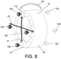
- Figure 8 shows an alternative embodiment in which the suspension elements (12a) and (12b) are different depending on the flat face (13) of the inertial mass (10) on which they are located.
- the directions of action (41) and (42) have the same elasticity, but the elasticity of the elements (12a) is different relative to the elements (12b), thus achieving a rotational vibration mode of the inertial mass (10) represented by the arrow (43).
- the vibration frequency can be tuned taking into account this rotational vibration mode, expanding the range of frequencies to be damped.
- Figure 9 shows an alternative embodiment to the embodiment of Figure 8 to achieve a similar effect.
- an inertial mass (10) made up of two annular masses (101) and (102) having a different density and size. Therefore, it is possible to displace the centre of gravity of the inertial mass (10), causing a difference in weight to be suspended by the suspension elements on each flat face (13).
- said difference in weight causes there to be a different level of suspension on each flat face (13), so that in a manner analogous to the embodiment of figure 8 , the rotational vibration mode can be achieved, where the suspension elements (12) have a symmetrical distribution and the same elasticity for each flat face (13).
Landscapes
- Engineering & Computer Science (AREA)
- General Engineering & Computer Science (AREA)
- Mechanical Engineering (AREA)
- Vibration Prevention Devices (AREA)
Priority Applications (1)
| Application Number | Priority Date | Filing Date | Title |
|---|---|---|---|
| EP23383296.3A EP4570427A1 (fr) | 2023-12-14 | 2023-12-14 | Système d'amortissement passif pour arbre rotatif en porte-à-faux |
Applications Claiming Priority (1)
| Application Number | Priority Date | Filing Date | Title |
|---|---|---|---|
| EP23383296.3A EP4570427A1 (fr) | 2023-12-14 | 2023-12-14 | Système d'amortissement passif pour arbre rotatif en porte-à-faux |
Publications (1)
| Publication Number | Publication Date |
|---|---|
| EP4570427A1 true EP4570427A1 (fr) | 2025-06-18 |
Family
ID=89853429
Family Applications (1)
| Application Number | Title | Priority Date | Filing Date |
|---|---|---|---|
| EP23383296.3A Pending EP4570427A1 (fr) | 2023-12-14 | 2023-12-14 | Système d'amortissement passif pour arbre rotatif en porte-à-faux |
Country Status (1)
| Country | Link |
|---|---|
| EP (1) | EP4570427A1 (fr) |
Citations (5)
| Publication number | Priority date | Publication date | Assignee | Title |
|---|---|---|---|---|
| CN111819031A (zh) * | 2018-03-09 | 2020-10-23 | 索拉路斯有限公司 | 具有阻尼的振动吸收器的立式车床 |
| CN114206530A (zh) * | 2019-07-11 | 2022-03-18 | Gkn航空公司 | 用于铣床的阻尼器 |
| US20220226912A1 (en) * | 2021-01-21 | 2022-07-21 | Iscar, Ltd. | Tool holder having anti-vibration arrangement and cutting tool provided with tool holder |
| KR20220156559A (ko) * | 2020-03-31 | 2022-11-25 | 마큐 에이비 | 공구 어셈블리용 공구 홀더 및 공구 홀더를 포함하는 공구 어셈블리 |
| EP4289531A1 (fr) * | 2022-06-10 | 2023-12-13 | Ideko, S.Coop. | Système d'amortissement des vibrations d'une barre de forage |
-
2023
- 2023-12-14 EP EP23383296.3A patent/EP4570427A1/fr active Pending
Patent Citations (5)
| Publication number | Priority date | Publication date | Assignee | Title |
|---|---|---|---|---|
| CN111819031A (zh) * | 2018-03-09 | 2020-10-23 | 索拉路斯有限公司 | 具有阻尼的振动吸收器的立式车床 |
| CN114206530A (zh) * | 2019-07-11 | 2022-03-18 | Gkn航空公司 | 用于铣床的阻尼器 |
| KR20220156559A (ko) * | 2020-03-31 | 2022-11-25 | 마큐 에이비 | 공구 어셈블리용 공구 홀더 및 공구 홀더를 포함하는 공구 어셈블리 |
| US20220226912A1 (en) * | 2021-01-21 | 2022-07-21 | Iscar, Ltd. | Tool holder having anti-vibration arrangement and cutting tool provided with tool holder |
| EP4289531A1 (fr) * | 2022-06-10 | 2023-12-13 | Ideko, S.Coop. | Système d'amortissement des vibrations d'une barre de forage |
Similar Documents
| Publication | Publication Date | Title |
|---|---|---|
| CN104246287B (zh) | 旋转减振组件 | |
| EP0808431B1 (fr) | Dispositifs d'entrainement | |
| JP2569276B2 (ja) | ねじり振動減衰器 | |
| US3670593A (en) | Series type vibration damper | |
| CN109641279B (zh) | 可旋转组件、加工杆组件及其方法 | |
| US3462136A (en) | Tuned viscous vibration dampers | |
| JP2004286209A (ja) | ねじれ振動ダンパー | |
| EP0756104A2 (fr) | Ensemble de disque amortisseur contenant un mécanisme de frottement avec des éléments de friction améliorés et des membres de ressort pour amortissement des vibrations avec des assiettes de ressort améliorées | |
| EP3575623B1 (fr) | Accouplement d'arbre | |
| JP2014534397A (ja) | 改良ガイド装置を備えた振り子式振動子タイプのダンパシステム | |
| CN102959282A (zh) | 扭转振动减振装置 | |
| KR100598843B1 (ko) | 비틀림 진동 댐퍼 | |
| US9919365B2 (en) | Side milling cutter for slot cutting | |
| CN107709826A (zh) | 振动衰减装置 | |
| US5935008A (en) | Flywheel assembly having a damper mechanism that includes a friction hysterisis generating device | |
| KR20030062418A (ko) | 밸런서 | |
| US5239886A (en) | Stability high gain and dynamic stiffness servo axis drive system and method | |
| EP4570427A1 (fr) | Système d'amortissement passif pour arbre rotatif en porte-à-faux | |
| US5205190A (en) | Stability high gain and dynamic stiffness servo axis drive system and method | |
| KR101087884B1 (ko) | 토크 전달 장치용 플랙시블 플라이휠 | |
| KR100527443B1 (ko) | 비틀림 진동 댐퍼 | |
| CN215186252U (zh) | 用于电动机的调谐质量阻尼器 | |
| JP4625791B2 (ja) | スプリングシート及びスプリング組立体 | |
| CN111386410B (zh) | 离心摆和用于机动车的驱动装置 | |
| KR102626148B1 (ko) | 베어링 댐퍼를 구비한 압축기 장치 및 베어링 댐퍼를 구비한 장치 |
Legal Events
| Date | Code | Title | Description |
|---|---|---|---|
| PUAI | Public reference made under article 153(3) epc to a published international application that has entered the european phase |
Free format text: ORIGINAL CODE: 0009012 |
|
| STAA | Information on the status of an ep patent application or granted ep patent |
Free format text: STATUS: THE APPLICATION HAS BEEN PUBLISHED |
|
| AK | Designated contracting states |
Kind code of ref document: A1 Designated state(s): AL AT BE BG CH CY CZ DE DK EE ES FI FR GB GR HR HU IE IS IT LI LT LU LV MC ME MK MT NL NO PL PT RO RS SE SI SK SM TR |
|
| STAA | Information on the status of an ep patent application or granted ep patent |
Free format text: STATUS: REQUEST FOR EXAMINATION WAS MADE |
|
| 17P | Request for examination filed |
Effective date: 20250924 |