EP4570431A1 - Rotierendes abrichtwerkzeug - Google Patents
Rotierendes abrichtwerkzeug Download PDFInfo
- Publication number
- EP4570431A1 EP4570431A1 EP23888584.2A EP23888584A EP4570431A1 EP 4570431 A1 EP4570431 A1 EP 4570431A1 EP 23888584 A EP23888584 A EP 23888584A EP 4570431 A1 EP4570431 A1 EP 4570431A1
- Authority
- EP
- European Patent Office
- Prior art keywords
- rotary dresser
- diameter
- abrasive grain
- grain layer
- grindstone
- Prior art date
- Legal status (The legal status is an assumption and is not a legal conclusion. Google has not performed a legal analysis and makes no representation as to the accuracy of the status listed.)
- Pending
Links
Images







Classifications
-
- B—PERFORMING OPERATIONS; TRANSPORTING
- B24—GRINDING; POLISHING
- B24B—MACHINES, DEVICES, OR PROCESSES FOR GRINDING OR POLISHING; DRESSING OR CONDITIONING OF ABRADING SURFACES; FEEDING OF GRINDING, POLISHING, OR LAPPING AGENTS
- B24B53/00—Devices or means for dressing or conditioning abrasive surfaces
- B24B53/04—Devices or means for dressing or conditioning abrasive surfaces of cylindrical or conical surfaces on abrasive tools or wheels
- B24B53/053—Devices or means for dressing or conditioning abrasive surfaces of cylindrical or conical surfaces on abrasive tools or wheels using a rotary dressing tool
-
- B—PERFORMING OPERATIONS; TRANSPORTING
- B24—GRINDING; POLISHING
- B24B—MACHINES, DEVICES, OR PROCESSES FOR GRINDING OR POLISHING; DRESSING OR CONDITIONING OF ABRADING SURFACES; FEEDING OF GRINDING, POLISHING, OR LAPPING AGENTS
- B24B53/00—Devices or means for dressing or conditioning abrasive surfaces
- B24B53/06—Devices or means for dressing or conditioning abrasive surfaces of profiled abrasive wheels
- B24B53/07—Devices or means for dressing or conditioning abrasive surfaces of profiled abrasive wheels by means of forming tools having a shape complementary to that to be produced, e.g. blocks, profile rolls
-
- B—PERFORMING OPERATIONS; TRANSPORTING
- B24—GRINDING; POLISHING
- B24B—MACHINES, DEVICES, OR PROCESSES FOR GRINDING OR POLISHING; DRESSING OR CONDITIONING OF ABRADING SURFACES; FEEDING OF GRINDING, POLISHING, OR LAPPING AGENTS
- B24B53/00—Devices or means for dressing or conditioning abrasive surfaces
- B24B53/12—Dressing tools; Holders therefor
- B24B53/14—Dressing tools equipped with rotary rollers or cutters; Holders therefor
-
- B—PERFORMING OPERATIONS; TRANSPORTING
- B24—GRINDING; POLISHING
- B24D—TOOLS FOR GRINDING, BUFFING OR SHARPENING
- B24D3/00—Physical features of abrasive bodies, or sheets, e.g. abrasive surfaces of special nature; Abrasive bodies or sheets characterised by their constituents
- B24D3/02—Physical features of abrasive bodies, or sheets, e.g. abrasive surfaces of special nature; Abrasive bodies or sheets characterised by their constituents the constituent being used as bonding agent
- B24D3/04—Physical features of abrasive bodies, or sheets, e.g. abrasive surfaces of special nature; Abrasive bodies or sheets characterised by their constituents the constituent being used as bonding agent and being essentially inorganic
- B24D3/06—Physical features of abrasive bodies, or sheets, e.g. abrasive surfaces of special nature; Abrasive bodies or sheets characterised by their constituents the constituent being used as bonding agent and being essentially inorganic metallic or mixture of metals with ceramic materials, e.g. hard metals, "cermets", cements
-
- B—PERFORMING OPERATIONS; TRANSPORTING
- B24—GRINDING; POLISHING
- B24D—TOOLS FOR GRINDING, BUFFING OR SHARPENING
- B24D5/00—Bonded abrasive wheels, or wheels with inserted abrasive blocks, designed for acting only by their periphery; Bushings or mountings therefor
- B24D5/02—Wheels in one piece
Definitions
- the present disclosure relates to a rotary dresser.
- the present application claims priority based on Japanese Patent Application No. 2022-178078 filed on November 7, 2022 , and priority based on Japanese Patent Application No. 2023-051173 filed on March 28, 2023 , the entire contents of which are incorporated herein by reference.
- Japanese Patent Laying-Open No. 2012-091292 (PTL 1) describes a rotary dresser, as an example of a rotary dresser that modifies the shape and a grinding surface of a forming grindstone.
- a rotary dresser includes a base metal having an outer circumferential surface, and an abrasive grain layer provided on the outer circumferential surface of the base metal, wherein the abrasive grain layer has a binder provided on the base metal, and abrasive grains fixed in a single layer by the binder, the abrasive grain layer of the rotary dresser has a diameter that differs depending on a portion, the diameter of the abrasive grain layer has a diameter difference of 5% or more depending on the portion, the abrasive grains appearing on a surface of the abrasive grain layer are each provided with a working surface formed to be flat, and a proportion of an area of the working surfaces in the surface of the abrasive grain layer is smaller at a portion in which the abrasive grain layer has a larger diameter.
- the grindstone When a grindstone is dressed by a forming rotary dresser, the grindstone has a small diameter at a portion in which the rotary dresser has a large diameter, and the grindstone has a large diameter at a portion in which the rotary dresser has a small diameter. Further, in dressing a grindstone for grinding an outer diameter in which the dressing resistance becomes problematic, the diameter of the rotary dresser is generally smaller than the diameter of the grindstone in most cases, and the rotation speed of the rotary dresser during dressing is also lower than that of the grindstone.
- Rotation directions of the rotary dresser and the grindstone that are opposite to each other are generally used, and rotation directions of the rotary dresser and the grindstone that are the same direction (up-dressing) are not used except for a case where there is such a special reason that the rotary dresser has a deteriorated sharpness and thus cannot perform dressing.
- a circumferential speed ratio between a large-diameter portion of the rotary dresser and the grindstone differs from a circumferential speed ratio between a small-diameter portion of the rotary dresser and the grindstone.
- a circumferential speed ratio V1 (VRD/V grindstone) between the small-diameter portion of the rotary dresser and a large-diameter portion of the grindstone is small
- a circumferential speed ratio V2 (VRD/V grindstone) between the large-diameter portion of the rotary dresser and a small-diameter portion of the grindstone becomes large and approaches 1.
- the dressing resistance greatly differs between the large-diameter portion and the small-diameter portion of the rotary dresser, and there is a portion having a high dressing resistance. Accordingly, chatter or the like occurs, and the dressed grindstone tends to have a deteriorated accuracy.
- the rotary dresser according to the present disclosure is provided to solve problems as described above.
- Fig. 1 is a photograph of a rotary dresser 100 according to an embodiment of the present disclosure.
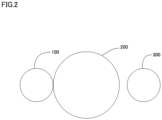
- Fig. 2 is a view showing a state in which rotary dresser 100 and a grindstone 200 come into contact with each other and rotary dresser 100 dresses grindstone 200.
- Fig. 3 is a view showing a state in which grindstone 200 and a workpiece 300 come into contact with each other and grindstone 200 grinds workpiece 300.
- rotary dresser 100 as a diamond rotary dresser has a base metal 103, and an abrasive grain layer 101 as a super-abrasive grain layer provided on a surface of base metal 103.
- Base metal 103 is made of stainless steel, for example.
- Base metal 103 has a cylindrical shape, and abrasive grain layer 101 is provided on an outer circumferential surface of base metal 103.
- abrasive grain layer 101 diamonds as abrasive grains are fixed.
- CBN cubic boron nitride
- diamond and cubic boron nitride may be mixed.
- a groove 102 extending in a circumferential direction is formed in abrasive grain layer 101. This groove 102 is formed along the shape of a workpiece.
- Such rotary dresser 100 is used for dressing a so-called forming grindstone.
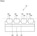
- Fig. 4 is a view showing a cross sectional structure of abrasive grain layer 101 along a direction from the center toward an outer circumference of rotary dresser 100.
- abrasive grain layer 101 is formed on the surface of base metal 103 with a low-melting-point alloy layer 104 being interposed therebetween.
- Abrasive grain layer 101 is produced by an inversion plating method, and has a binder 203 as a plated layer, and abrasive grains 204 fixed in a single layer.
- Abrasive grain layer 101 is fixed on base metal 103 by low-melting-point alloy layer 104.
- a ratio of a total area of a plurality of working surfaces 205 to an area of an imaginary surface 206 smoothly connecting working surfaces 205 is represented by a ratio S.
- Working surfaces 205 of abrasive grains 204 are formed by grinding or polishing abrasive grains 204.
- the area of working surfaces 205 can be adjusted by changing a time for grinding or polishing abrasive grains 204.
- abrasive grains 204 not only super-abrasive grains such as diamond and CBN but also conventional abrasive grains such as alumina can be used.
- Rotary dresser 100 includes base metal 103 having an outer circumferential surface 109, and abrasive grain layer 101 provided on outer circumferential surface 109 of base metal 103.
- Abrasive grain layer 101 has binder 203 provided on base metal 103, and abrasive grains 204 fixed in a single layer by binder 203, and abrasive grain layer 101 of rotary dresser 100 has a diameter that differs between a first portion and a second portion of abrasive grain layer 101.
- a diameter of abrasive grain layer 101 at the first portion is D1 and a diameter of abrasive grain layer 101 at the second portion is D2, (D1-D2)/D1 is 5% or more.
- the abrasive grains appearing on a surface of abrasive grain layer 101 are each provided with working surface 205 formed to be flat.
- a proportion of the area of working surfaces 205 in the surface of abrasive grain layer 101 is smaller at a portion in which abrasive grain layer 101 has a larger diameter.
- the proportion (ratio S) of the area of working surfaces 205 at a portion having a maximum diameter in abrasive grain layer 101 is 5% or more and 15% or less.
- the number of abrasive grains along one circumference of rotary dresser 100 is smaller at the portion in which abrasive grain layer 101 has a larger diameter.
- an interval between abrasive grains 204 is wider at the portion in which abrasive grain layer 101 has a larger diameter.
- Abrasive grains 204 are artificial synthesized diamonds, and crystal planes of the artificially synthesized diamond are oriented.
- the artificially synthesized diamonds are used as abrasive grains 204, they are joined such that the crystal planes thereof are substantially parallel with a joint surface of base metal 103, because the artificially synthesized diamonds have a shape in which the crystal planes of the diamonds clearly appear.
- abrasive grains 204 are densely joined in a stable manner, which can increase a working area ratio even with a small amount of grinding for forming the working surfaces on abrasive grains 204.
- the working surfaces can be easily formed, and abrasive grain layer 101 has an increased thickness, which leads to an improved life.
- abrasive grains 204 are linearly arranged on the surface of abrasive grain layer 101.
- the arrangement direction may be any of an axial direction of rotary dresser 100, the circumferential direction thereof, and a direction having an angle with respect to these directions, and may be linear or curved.
- Figs. 5 to 7 are schematic views of rotary dresser 100 shown to illustrate a method of measuring the proportion of the area of the working surfaces.
- rotary dresser 100 rotates about a rotation axis 108.
- outer circumferential surface 109 has a stair-like shape.
- a position having a diameter that differs by 5% or more from the diameter at the position selected in (1) above is selected. It is assumed that a portion having diameter D2 is selected. (D1-D2)/D1 is 5% or more. Further, it is assumed that a portion having a diameter D3 is selected. (D2-D3)/D2 is 5% or more.
- positions at which diameters differ by 5%, such as 5%, 10%, and 15%, from the diameter at the position selected in (1) above are selected.
- an arbitrary position (a position of a line A) is selected.
- a position of a line B at which a diameter differs by 5% from a diameter at the position of line A is selected.
- a position of a line C at which a diameter differs by 5% from the diameter at the position of line B is selected.
- a position of a line D at which a diameter differs by 5% from the diameter at the position of line C is selected.
- a position of a line A outside groove 102 is selected. It is assumed that a diameter at the position of line A outside the groove is D1, and a diameter at a position of a line B inside groove 102 is D2. When (D1-D2)/D1 is 5% or more, measurement is also performed on line B.
- the proportion of the area of the working surfaces of the abrasive grains is measured by procedures of curved surface correction, cut-off correction, threshold value setting, and area measurement, using a measuring device VR5000 manufactured by Keyence.
- the measuring machine is VR5000 manufactured by Keyence.
- the measurement principle is a "light-section method".
- the analysis procedure includes the following (1) to (3).
- (3) Set a threshold value and calculate a working area. In each of line A, line B, line C, and line D, an average value of working areas measured at 10 positions is defined as a working area in the line.
- the dressing resistance becomes higher as a circumferential speed difference between rotary dresser 100 and the grindstone in contact with rotary dresser 100 becomes smaller (as the circumferential speed ratio becomes closer to 1).
- the circumferential speed difference varies depending on the outer diameter of rotary dresser 100. It is not possible to change a circumferential speed of a forming dresser depending on the location. Accordingly, the dressing resistance can be reduced by reducing the proportion of working surfaces 205 of abrasive grains 204 at a portion having a large outer diameter in rotary dresser 100.
- the dressing resistance of the entire rotary dresser can be reduced. Further, since the difference in dressing resistance between the large-diameter portion and a small-diameter portion of the rotary dresser is reduced, the dressed grindstone has an improved accuracy. Furthermore, wear at the large-diameter portion and the small-diameter portion of the abrasive grain layer can be substantially uniformized, and the life of the rotary dresser can be improved.
- Head portions of the abrasive grains working on the grindstone when the rotary dresser performs dressing are provided with the working surfaces, and the proportion of the area of the working surfaces has a great influence on the dressing resistance.
- a larger-diameter portion of the forming rotary dresser works on a smaller-diameter portion of the grindstone, and the circumferential speed ratio at this portion approaches 1. Accordingly, the dressing resistance increases.
- the dressing resistance at the large-diameter portion of the rotary dresser is reduced, and the dressing resistance of the entire rotary dresser is also reduced.
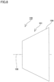
- Fig. 8 is a schematic view of rotary dresser 100 before dressing fabricated in an Example. Tables 1 and 2 show details thereof.
- Table 1 Sample No. Position Diameter [mm] Working Area Ratio [%] Number of Abrasive Grains [/Circumference] 2 mm-width Average Abrasive Grain Interval [mm] Total Number of Abrasive Grains 1 Left (small diameter) 75.36 12.9 187 1.3 2,708 Center 92.68 10.1 175 1.7 Right (large diameter) 110 7.7 162 2.1 2 Left (small diameter) 75.36 12.4 182 1.3 2,708 Center 92.68 10.0 175 1.7 Right (large diameter) 110 7.8 167 2.1 3 Left (small diameter) 75.36 11.9 178 1.3 2,708 Center 92.68 9.7 175 1.7 Right (large diameter) 110 7.8 171 2.0 4 Left (small diameter) 75.36 12.1 175 1.4 2,708 Center 92.68 10.1 175 1.7 Right (large diameter) 110 8.3 175
- the "2 mm-width Average Abrasive Grain Interval” is a distance obtained by "a circumferential length of a central portion within a width of 2 mm / the number of abrasive grains within the width of 2 mm" at each portion. It should be noted that, for an abrasive grain which is located at an outer circumferential edge portion of a region having a width of 2 mm and a part of which is located within this region, the number of the abrasive grain is counted as 0.5.
- Abrasive grains 204 of rotary dresser 100 are made of diamond, base metal 103 ( Fig. 3 ) is made of stainless steel, and binder 203 ( Fig. 3 ) is made of nickel plating.
- the diameter of abrasive grains 204 is #20/25 (average grain diameter: 700 ⁇ m to 850 ⁇ m).
- Abrasive grains 204 are fixed at intervals in the circumferential direction, and are linearly arranged.
- This rotary dresser 100 is used for dressing grindstone 200 as shown in Fig. 2 .
- Grindstone 200 ( Fig. 2 ) to be dressed is a grindstone manufactured by Kure-Norton Co., Ltd, having a mesh of #60 (average grain diameter: 250 ⁇ m) and a bonding degree of K.
- the material for grindstone 200 is WA.
- Workpiece 300 ( Fig. 3 ) is a round bar having a diameter of 100 mm and a thickness (length in a rotation axis direction) of 130 mm, and is made of S45C.
- Rotation directions of rotary dresser 100 and grindstone 200 are opposite to each other (down-dressing). Thereby, a grinding fluid is sucked into between rotary dresser 100 and grindstone 200. Rotation directions of grindstone 200 and workpiece 300 are also opposite to each other.
- Rotary dresser 100 has an average outer diameter of 93 mm, a rotation speed of 1200 rpm, and a circumferential speed of 5.8 m/s.
- Grindstone 200 has an average outer diameter of 248 mm, a rotation speed of 1490 (rpm), and a circumferential speed of 19.4 m/s.
- the circumferential speed ratio represented by an average circumferential speed of rotary dresser 100 / an average circumferential speed of grindstone 200 is 0.3.
- Dressing Resistance [N] Workpiece Roughness Ra [ ⁇ m] RD Radius Wear Amount at 100 Times of Dressing [ ⁇ m] Determination of Dressing Resistance 1 32.9 0.163 1.03 A 0.204 0.95 0.259 0.87 2 32.8 0.163 1.07 A 0.210 0.99 0.254 0.88 3 32.6 0.163 1.05 A 0.206 0.96 0.262 0.88 4 33.0 0.170 1.11 A 0.209 1.00 0.259 0.84 5 33.0 0.168 1.16 A 0.208 0.99 0.243 0.83 [Table 4] Sample No.
- Dressing Resistance [N] Workpiece Roughness Ra[ ⁇ m] RD Radius Wear Amount at 100 Times of Dressing [ ⁇ m] Determination of Dressing Resistance 6 33.9 0.179 1.21 B 0.210 0.98 0.242 0.78 7 35.8 0.192 1.43 C 0.211 0.97 0.224 0.71 8 34.6 0.178 0.18 C 0.210 0.21 0.233 0.23 9 26.5 0.211 2.78 A 0.254 2.46 0.318 2.11 10 34.6 0.178 0.178 C 0.210 0.210 0.233 0.233
- the "Dressing Resistance” is a resistance for rotating the rotary dresser, obtained by measuring a load in a cutting direction using a piezoelectric sensor "Multicomponent Dynamometer 9257B” manufactured by Kistler.
- the "Workpiece Roughness” is a surface roughness of workpiece 300 ground by grindstone 200 immediately after dressing in each of 100 times of dressing, and is an average value of 100 measurement values measured using a stylus surface roughness meter.
- RD Radius Wear Amount at 100 Times of Dressing is an amount of wear of the rotary dresser after 100 times of dressing described above in (Description of Dressing Step).
- Fig. 9 is a schematic view of rotary dresser 100 after 100 times of dressing. As shown in Fig. 9 , a recess 119 is formed in outer circumferential surface 109 at the end of 100 times of dressing. A region in which recess 119 is formed is a dressing region 118. Recess 119 is formed because the portion of recess 119 mainly comes into contact with grindstone 200.
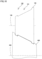
- Fig. 10 is a schematic view of rotary dresser 100 after 100 times of dressing and a shape transfer material machining grindstone 400 in contact with rotary dresser 100.
- rotary dresser 100 is rotated about rotation axis 108, and shape transfer material machining grindstone 400 is rotated about a rotation axis 408.
- Shape transfer material machining grindstone 400 is dressed. Thereby, the shape of an outer circumferential surface of abrasive grain layer 101 of rotary dresser 100 is transferred to shape transfer material machining grindstone 400.
- Shape transfer material machining grindstone 400 used has a grain size of #60 (average grain diameter: 250 ⁇ m), an abrasive grain type of WA, and a width of more than or equal to the width of rotary dresser 100.
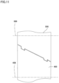
- Fig. 11 is a schematic view of shape transfer material machining grindstone 400 and a shape transfer material 500 in contact with shape transfer material machining grindstone 400.
- shape transfer material machining grindstone 400 is rotated about rotation axis 408, and shape transfer material 500 is rotated about a rotation axis 508.
- round bar-like shape transfer material 500 made of S45C is machined using shape transfer material machining grindstone 400.
- Fig. 12 is a schematic view of shape transfer material 500 to which the shape of rotary dresser 100 after 100 times of dressing is transferred. As shown in Fig. 12 , the shape transferred to shape transfer material 500 is measured in a measurement region 518, using a shape measuring device. Any ordinary shape measuring device may be used for measurement.
- Fig. 13 is a schematic view for illustrating a method of measuring a depth of a recess 519 as a wear trace formed on shape transfer material 500.
- Fig. 13 shows minute irregularities of a surface observed in measurement region 518.
- An intermediate point (average position) of each of reference portion 521 and reference portion 522 of rotary dresser RD transferred to shape transfer material 500 is calculated by the shape measuring device.
- An intermediate point 523 is the intermediate point of reference portion 521.
- An intermediate point 524 is the intermediate point of reference portion 522.
- an intermediate point 526 of the portion worked by rotary dresser 100 during dressing is calculated by the shape measuring device.
- a distance L between a straight line 525 connecting intermediate point 523 of reference portion 521 with intermediate point 524 of reference portion 522 and intermediate point 526 of the portion worked by rotary dresser 100 during dressing indicates the "RD Radius Wear Amount at 100 Times of Dressing". This distance is a distance in a direction perpendicular to straight line 525.
- Sample No. 7 in which the working area ratio at the small-diameter portion is small, is evaluated as "C" in the determination of the dressing resistance.
- Sample Nos. 1 to 6 and 9 in which the working area ratio at the small-diameter portion is large, are evaluated as "A" or "B” in the determination of the dressing resistance.
- the dressing resistance is extremely low, and thus it can be said that excellent results are exhibited.
- a rotary dresser including:
- the rotary dresser according to any one of Additional Aspects 1 to 4, wherein the abrasive grains are artificially synthesized diamonds, and crystal planes of the artificially synthesized diamonds are oriented.
- 100 rotary dresser; 101: abrasive grain layer; 102: groove; 103: base metal; 104: low-melting-point alloy layer; 108, 408, 508: rotation axis; 109: outer circumferential surface; 118: dressing region; 203: binder; 204: super-abrasive grains; 205: top surface; 206: imaginary surface; 300: workpiece; 400: shape transfer material machining grindstone; 500: shape transfer material; 518: measurement region; 521, 522: reference portion; 523, 524, 526: intermediate point; 525: straight line.
Landscapes
- Engineering & Computer Science (AREA)
- Mechanical Engineering (AREA)
- Chemical & Material Sciences (AREA)
- Ceramic Engineering (AREA)
- Inorganic Chemistry (AREA)
- Polishing Bodies And Polishing Tools (AREA)
- Grinding-Machine Dressing And Accessory Apparatuses (AREA)
Applications Claiming Priority (3)
| Application Number | Priority Date | Filing Date | Title |
|---|---|---|---|
| JP2022178078 | 2022-11-07 | ||
| JP2023051173 | 2023-03-28 | ||
| PCT/JP2023/039375 WO2024101236A1 (ja) | 2022-11-07 | 2023-11-01 | ロータリードレッサ |
Publications (1)
| Publication Number | Publication Date |
|---|---|
| EP4570431A1 true EP4570431A1 (de) | 2025-06-18 |
Family
ID=90183441
Family Applications (1)
| Application Number | Title | Priority Date | Filing Date |
|---|---|---|---|
| EP23888584.2A Pending EP4570431A1 (de) | 2022-11-07 | 2023-11-01 | Rotierendes abrichtwerkzeug |
Country Status (3)
| Country | Link |
|---|---|
| EP (1) | EP4570431A1 (de) |
| JP (1) | JP7450134B1 (de) |
| CN (1) | CN120202084A (de) |
Family Cites Families (2)
| Publication number | Priority date | Publication date | Assignee | Title |
|---|---|---|---|---|
| JP5042208B2 (ja) * | 2008-10-15 | 2012-10-03 | 株式会社アライドマテリアル | 超砥粒工具およびその製造方法 |
| JP7309772B2 (ja) * | 2021-03-25 | 2023-07-18 | 株式会社ノリタケカンパニーリミテド | ロータリードレッサ |
-
2023
- 2023-11-01 JP JP2024501775A patent/JP7450134B1/ja active Active
- 2023-11-01 CN CN202380076176.2A patent/CN120202084A/zh active Pending
- 2023-11-01 EP EP23888584.2A patent/EP4570431A1/de active Pending
Also Published As
| Publication number | Publication date |
|---|---|
| CN120202084A (zh) | 2025-06-24 |
| JPWO2024101236A1 (de) | 2024-05-16 |
| JP7450134B1 (ja) | 2024-03-14 |
Similar Documents
| Publication | Publication Date | Title |
|---|---|---|
| US6224469B1 (en) | Combined cutting and grinding tool | |
| EP1813387A1 (de) | Schleifscheibe | |
| EP0543941A1 (de) | Universalabrichtrolle sowie verfahren und vorrichtung zum abrichten von topfschleifscheiben | |
| JPS63318265A (ja) | ブロック式総形トルーイング工具 | |
| CN116323061A (zh) | 用于切削齿轮的方法、齿轮切削工具和齿轮切削机 | |
| EP4570431A1 (de) | Rotierendes abrichtwerkzeug | |
| JP3299523B2 (ja) | 硬質発泡樹脂パッドの旋削溝加工用工具 | |
| CN108698202B (zh) | 磨料工具 | |
| JPS6246539Y2 (de) | ||
| JP3989211B2 (ja) | 高平滑研削加工方法 | |
| WO2024101236A1 (ja) | ロータリードレッサ | |
| EP3616838B1 (de) | Rotierender formabrichter und abrichtverfahren | |
| JPS591555B2 (ja) | ロ−タリダイヤモンドドレツサ | |
| KR102517771B1 (ko) | 양두 연삭 방법 | |
| CN116213844A (zh) | 磨削锥齿轮的方法 | |
| JP2024179655A (ja) | ロータリードレッサ | |
| JPH09254040A (ja) | 研削用砥石及びレンズ研削用砥石 | |
| JP2003260646A (ja) | 非軸対称非球面の研削加工方法及び加工装置 | |
| US20250196291A1 (en) | Rotary dresser and method of manufacturing the same | |
| JPH0223284B2 (de) | ||
| JP4342361B2 (ja) | センタレス研削砥石 | |
| RU2208510C2 (ru) | Правящий инструмент | |
| JPH11138446A (ja) | 多刃研削工具の製造方法 | |
| JPS6322269A (ja) | ダイヤモンド砥石の同時ツル−イング及びドレツシング方法と複合研削砥石 | |
| JPH0911129A (ja) | ドレスギヤ |
Legal Events
| Date | Code | Title | Description |
|---|---|---|---|
| STAA | Information on the status of an ep patent application or granted ep patent |
Free format text: STATUS: THE INTERNATIONAL PUBLICATION HAS BEEN MADE |
|
| PUAI | Public reference made under article 153(3) epc to a published international application that has entered the european phase |
Free format text: ORIGINAL CODE: 0009012 |
|
| STAA | Information on the status of an ep patent application or granted ep patent |
Free format text: STATUS: REQUEST FOR EXAMINATION WAS MADE |
|
| 17P | Request for examination filed |
Effective date: 20250312 |
|
| AK | Designated contracting states |
Kind code of ref document: A1 Designated state(s): AL AT BE BG CH CY CZ DE DK EE ES FI FR GB GR HR HU IE IS IT LI LT LU LV MC ME MK MT NL NO PL PT RO RS SE SI SK SM TR |
|
| DAV | Request for validation of the european patent (deleted) | ||
| DAX | Request for extension of the european patent (deleted) |