EP4570488A1 - Verfahren und vorrichtung zur trockenherstellung einer steifen zelluloseschale und steife zelluloseschale - Google Patents
Verfahren und vorrichtung zur trockenherstellung einer steifen zelluloseschale und steife zelluloseschale Download PDFInfo
- Publication number
- EP4570488A1 EP4570488A1 EP23215964.0A EP23215964A EP4570488A1 EP 4570488 A1 EP4570488 A1 EP 4570488A1 EP 23215964 A EP23215964 A EP 23215964A EP 4570488 A1 EP4570488 A1 EP 4570488A1
- Authority
- EP
- European Patent Office
- Prior art keywords
- tray
- cellulose
- sub
- area
- blank segment
- Prior art date
- Legal status (The legal status is an assumption and is not a legal conclusion. Google has not performed a legal analysis and makes no representation as to the accuracy of the status listed.)
- Pending
Links
Images



Classifications
-
- B—PERFORMING OPERATIONS; TRANSPORTING
- B31—MAKING ARTICLES OF PAPER, CARDBOARD OR MATERIAL WORKED IN A MANNER ANALOGOUS TO PAPER; WORKING PAPER, CARDBOARD OR MATERIAL WORKED IN A MANNER ANALOGOUS TO PAPER
- B31B—MAKING CONTAINERS OF PAPER, CARDBOARD OR MATERIAL WORKED IN A MANNER ANALOGOUS TO PAPER
- B31B50/00—Making rigid or semi-rigid containers, e.g. boxes or cartons
- B31B50/59—Shaping sheet material under pressure
- B31B50/592—Shaping sheet material under pressure using punches or dies
-
- B—PERFORMING OPERATIONS; TRANSPORTING
- B27—WORKING OR PRESERVING WOOD OR SIMILAR MATERIAL; NAILING OR STAPLING MACHINES IN GENERAL
- B27N—MANUFACTURE BY DRY PROCESSES OF ARTICLES, WITH OR WITHOUT ORGANIC BINDING AGENTS, MADE FROM PARTICLES OR FIBRES CONSISTING OF WOOD OR OTHER LIGNOCELLULOSIC OR LIKE ORGANIC MATERIAL
- B27N3/00—Manufacture of substantially flat articles, e.g. boards, from particles or fibres
- B27N3/08—Moulding or pressing
- B27N3/18—Auxiliary operations, e.g. preheating, humidifying, cutting-off
-
- B—PERFORMING OPERATIONS; TRANSPORTING
- B27—WORKING OR PRESERVING WOOD OR SIMILAR MATERIAL; NAILING OR STAPLING MACHINES IN GENERAL
- B27N—MANUFACTURE BY DRY PROCESSES OF ARTICLES, WITH OR WITHOUT ORGANIC BINDING AGENTS, MADE FROM PARTICLES OR FIBRES CONSISTING OF WOOD OR OTHER LIGNOCELLULOSIC OR LIKE ORGANIC MATERIAL
- B27N3/00—Manufacture of substantially flat articles, e.g. boards, from particles or fibres
- B27N3/08—Moulding or pressing
- B27N3/20—Moulding or pressing characterised by using platen-presses
- B27N3/203—Moulding or pressing characterised by using platen-presses with heating or cooling means
-
- B—PERFORMING OPERATIONS; TRANSPORTING
- B27—WORKING OR PRESERVING WOOD OR SIMILAR MATERIAL; NAILING OR STAPLING MACHINES IN GENERAL
- B27N—MANUFACTURE BY DRY PROCESSES OF ARTICLES, WITH OR WITHOUT ORGANIC BINDING AGENTS, MADE FROM PARTICLES OR FIBRES CONSISTING OF WOOD OR OTHER LIGNOCELLULOSIC OR LIKE ORGANIC MATERIAL
- B27N5/00—Manufacture of non-flat articles
- B27N5/02—Hollow articles
-
- B—PERFORMING OPERATIONS; TRANSPORTING
- B31—MAKING ARTICLES OF PAPER, CARDBOARD OR MATERIAL WORKED IN A MANNER ANALOGOUS TO PAPER; WORKING PAPER, CARDBOARD OR MATERIAL WORKED IN A MANNER ANALOGOUS TO PAPER
- B31B—MAKING CONTAINERS OF PAPER, CARDBOARD OR MATERIAL WORKED IN A MANNER ANALOGOUS TO PAPER
- B31B50/00—Making rigid or semi-rigid containers, e.g. boxes or cartons
- B31B50/60—Uniting opposed surfaces or edges; Taping
- B31B50/64—Uniting opposed surfaces or edges; Taping by applying heat or pressure, e.g. by welding
-
- B—PERFORMING OPERATIONS; TRANSPORTING
- B31—MAKING ARTICLES OF PAPER, CARDBOARD OR MATERIAL WORKED IN A MANNER ANALOGOUS TO PAPER; WORKING PAPER, CARDBOARD OR MATERIAL WORKED IN A MANNER ANALOGOUS TO PAPER
- B31B—MAKING CONTAINERS OF PAPER, CARDBOARD OR MATERIAL WORKED IN A MANNER ANALOGOUS TO PAPER
- B31B50/00—Making rigid or semi-rigid containers, e.g. boxes or cartons
- B31B50/74—Auxiliary operations
- B31B50/741—Moistening; Drying; Cooling; Heating; Sterilizing
-
- B—PERFORMING OPERATIONS; TRANSPORTING
- B31—MAKING ARTICLES OF PAPER, CARDBOARD OR MATERIAL WORKED IN A MANNER ANALOGOUS TO PAPER; WORKING PAPER, CARDBOARD OR MATERIAL WORKED IN A MANNER ANALOGOUS TO PAPER
- B31F—MECHANICAL WORKING OR DEFORMATION OF PAPER, CARDBOARD OR MATERIAL WORKED IN A MANNER ANALOGOUS TO PAPER
- B31F1/00—Mechanical deformation without removing material, e.g. in combination with laminating
- B31F1/0077—Shaping by methods analogous to moulding, e.g. deep drawing techniques
-
- B—PERFORMING OPERATIONS; TRANSPORTING
- B65—CONVEYING; PACKING; STORING; HANDLING THIN OR FILAMENTARY MATERIAL
- B65D—CONTAINERS FOR STORAGE OR TRANSPORT OF ARTICLES OR MATERIALS, e.g. BAGS, BARRELS, BOTTLES, BOXES, CANS, CARTONS, CRATES, DRUMS, JARS, TANKS, HOPPERS, FORWARDING CONTAINERS; ACCESSORIES, CLOSURES, OR FITTINGS THEREFOR; PACKAGING ELEMENTS; PACKAGES
- B65D1/00—Rigid or semi-rigid containers having bodies formed in one piece, e.g. by casting metallic material, by moulding plastics, by blowing vitreous material, by throwing ceramic material, by moulding pulped fibrous material or by deep-drawing operations performed on sheet material
- B65D1/34—Trays or like shallow containers
-
- B—PERFORMING OPERATIONS; TRANSPORTING
- B65—CONVEYING; PACKING; STORING; HANDLING THIN OR FILAMENTARY MATERIAL
- B65D—CONTAINERS FOR STORAGE OR TRANSPORT OF ARTICLES OR MATERIALS, e.g. BAGS, BARRELS, BOTTLES, BOXES, CANS, CARTONS, CRATES, DRUMS, JARS, TANKS, HOPPERS, FORWARDING CONTAINERS; ACCESSORIES, CLOSURES, OR FITTINGS THEREFOR; PACKAGING ELEMENTS; PACKAGES
- B65D21/00—Nestable, stackable or joinable containers; Containers of variable capacity
- B65D21/02—Containers specially shaped, or provided with fittings or attachments, to facilitate nesting, stacking, or joining together
- B65D21/0201—Containers specially shaped, or provided with fittings or attachments, to facilitate nesting, stacking, or joining together stackable or joined together side-by-side
- B65D21/0206—Separate rigid or semi-rigid trays or cups joined together, e.g. separate trays connected by single foil closure or crimped together
-
- B—PERFORMING OPERATIONS; TRANSPORTING
- B27—WORKING OR PRESERVING WOOD OR SIMILAR MATERIAL; NAILING OR STAPLING MACHINES IN GENERAL
- B27N—MANUFACTURE BY DRY PROCESSES OF ARTICLES, WITH OR WITHOUT ORGANIC BINDING AGENTS, MADE FROM PARTICLES OR FIBRES CONSISTING OF WOOD OR OTHER LIGNOCELLULOSIC OR LIKE ORGANIC MATERIAL
- B27N3/00—Manufacture of substantially flat articles, e.g. boards, from particles or fibres
- B27N3/04—Manufacture of substantially flat articles, e.g. boards, from particles or fibres from fibres
-
- B—PERFORMING OPERATIONS; TRANSPORTING
- B27—WORKING OR PRESERVING WOOD OR SIMILAR MATERIAL; NAILING OR STAPLING MACHINES IN GENERAL
- B27N—MANUFACTURE BY DRY PROCESSES OF ARTICLES, WITH OR WITHOUT ORGANIC BINDING AGENTS, MADE FROM PARTICLES OR FIBRES CONSISTING OF WOOD OR OTHER LIGNOCELLULOSIC OR LIKE ORGANIC MATERIAL
- B27N3/00—Manufacture of substantially flat articles, e.g. boards, from particles or fibres
- B27N3/08—Moulding or pressing
- B27N3/10—Moulding of mats
- B27N3/14—Distributing or orienting the particles or fibres
-
- B—PERFORMING OPERATIONS; TRANSPORTING
- B31—MAKING ARTICLES OF PAPER, CARDBOARD OR MATERIAL WORKED IN A MANNER ANALOGOUS TO PAPER; WORKING PAPER, CARDBOARD OR MATERIAL WORKED IN A MANNER ANALOGOUS TO PAPER
- B31B—MAKING CONTAINERS OF PAPER, CARDBOARD OR MATERIAL WORKED IN A MANNER ANALOGOUS TO PAPER
- B31B2105/00—Rigid or semi-rigid containers made by assembling separate sheets, blanks or webs
-
- B—PERFORMING OPERATIONS; TRANSPORTING
- B31—MAKING ARTICLES OF PAPER, CARDBOARD OR MATERIAL WORKED IN A MANNER ANALOGOUS TO PAPER; WORKING PAPER, CARDBOARD OR MATERIAL WORKED IN A MANNER ANALOGOUS TO PAPER
- B31B—MAKING CONTAINERS OF PAPER, CARDBOARD OR MATERIAL WORKED IN A MANNER ANALOGOUS TO PAPER
- B31B2105/00—Rigid or semi-rigid containers made by assembling separate sheets, blanks or webs
- B31B2105/002—Making boxes characterised by the shape of the blanks from which they are formed
- B31B2105/0024—Making boxes having all side walls attached to the bottom
-
- B—PERFORMING OPERATIONS; TRANSPORTING
- B31—MAKING ARTICLES OF PAPER, CARDBOARD OR MATERIAL WORKED IN A MANNER ANALOGOUS TO PAPER; WORKING PAPER, CARDBOARD OR MATERIAL WORKED IN A MANNER ANALOGOUS TO PAPER
- B31B—MAKING CONTAINERS OF PAPER, CARDBOARD OR MATERIAL WORKED IN A MANNER ANALOGOUS TO PAPER
- B31B2110/00—Shape of rigid or semi-rigid containers
- B31B2110/10—Shape of rigid or semi-rigid containers having a cross section of varying size or shape, e.g. conical or pyramidal
-
- B—PERFORMING OPERATIONS; TRANSPORTING
- B31—MAKING ARTICLES OF PAPER, CARDBOARD OR MATERIAL WORKED IN A MANNER ANALOGOUS TO PAPER; WORKING PAPER, CARDBOARD OR MATERIAL WORKED IN A MANNER ANALOGOUS TO PAPER
- B31B—MAKING CONTAINERS OF PAPER, CARDBOARD OR MATERIAL WORKED IN A MANNER ANALOGOUS TO PAPER
- B31B2110/00—Shape of rigid or semi-rigid containers
- B31B2110/30—Shape of rigid or semi-rigid containers having a polygonal cross section
- B31B2110/35—Shape of rigid or semi-rigid containers having a polygonal cross section rectangular, e.g. square
-
- B—PERFORMING OPERATIONS; TRANSPORTING
- B31—MAKING ARTICLES OF PAPER, CARDBOARD OR MATERIAL WORKED IN A MANNER ANALOGOUS TO PAPER; WORKING PAPER, CARDBOARD OR MATERIAL WORKED IN A MANNER ANALOGOUS TO PAPER
- B31B—MAKING CONTAINERS OF PAPER, CARDBOARD OR MATERIAL WORKED IN A MANNER ANALOGOUS TO PAPER
- B31B2120/00—Construction of rigid or semi-rigid containers
- B31B2120/002—Construction of rigid or semi-rigid containers having contracted or rolled necks, having shoulders
-
- B—PERFORMING OPERATIONS; TRANSPORTING
- B31—MAKING ARTICLES OF PAPER, CARDBOARD OR MATERIAL WORKED IN A MANNER ANALOGOUS TO PAPER; WORKING PAPER, CARDBOARD OR MATERIAL WORKED IN A MANNER ANALOGOUS TO PAPER
- B31B—MAKING CONTAINERS OF PAPER, CARDBOARD OR MATERIAL WORKED IN A MANNER ANALOGOUS TO PAPER
- B31B2120/00—Construction of rigid or semi-rigid containers
- B31B2120/20—Construction of rigid or semi-rigid containers provided with two or more compartments
Definitions
- the present invention relates in general to the field of method and apparatus for dry manufacturing of rigid cellulose products having non-flat general shape from cellulose blank.
- Such cellulose products may be used for packaging, storing, transporting and/or displaying other products such as electronics, tools, jewelry, food, dairy products, cosmetics, etc., and/or may be used as single/multiple use disposable articles.
- the present invention also relates to such rigid cellulose products.
- cellulose products means products that mainly consists of the cellulose part of organic matter.
- the present invention relates specifically to an apparatus and a method for dry manufacturing rigid cellulose trays having at least two compartments separated by a partition, the rigid cellulose tray comprising a first sub-tray and a second sub-tray.
- the first sub-tray comprises a bottom portion for receiving a first item and a circumferential wall connected to and extending in the axial direction upwards from the bottom portion
- the second sub-tray comprises a bottom portion for receiving a second item and a circumferential wall connected to and extending in the axial direction upwards from the bottom portion
- the first sub-tray is connected to the second sub-tray via said partition.
- a biomaterial commonly used for packaging is wet moulded pulp based on cellulose fibres.
- Such wet moulded pulp has the advantage of being considered as a sustainable packaging material, since it is produced from biomaterials and can be recycled after use.
- Wet moulded pulp comprises more or less only water and separated cellulose fibers, and consequently, wet moulded pulp has been popular to use for primary packaging applications (packaging next to the article), for secondary packaging applications (assembly of such primary packages), as well as for manufacturing of disposable articles/products.
- One advantage of using wet-forming techniques is that the moulding tool is filled with a wet cellulose slurry and thereafter the cellulose slurry is dried and obtains the shape of the moulding tool without any risk of cracking of the moulded cellulose product at the transitional portion between adjacent compartments of a multicompartment cellulose tray.
- dry-forming techniques wherein rigid cellulose products are manufactured from separated cellulose fibres that are introduced into a product forming unit in the shape of a cellulose blank/web, wherein the cellulose blank is formed into the shape of the intended cellulose product and wherein the cellulose fibres are bonded to each other using heat and pressure.
- the dry-forming techniques comprises different steps of generating an air-laid cellulose blank, that is fed into a product forming unit, i.e. a thermo-forming press.
- One known way to try to solve the problem of cellulose trays having uneven thickness is to provide a coating or the like to the projections of the male mould part and to the recesses of the female mould part, in order to decrease the friction between the cellulose blank and the moulding tool in order to counteract material draw and elongation.
- Such measures may have some positive effect during moulding/pressing of cellulose trays having one compartment.
- the inventors of the present invention have concluded by thorough research that such measures do not have any beneficial effect on the problem concerning material draw and elongation during moulding/pressing rigid cellulose trays having a plurality of compartments, on the contrary it has negative effect resulting in more cracks at the transitional region between the compartments.
- An alternative technique to dry manufacture rigid cellulose trays having a plurality of compartments is to separately manufacture each of two sub-trays according to known technique for manufacturing rigid cellulose products. Thereafter these two sub-trays are connected to each other using glue or another adhesive.
- glue or other adhesive it is a major risk that the cellulose product is miscoloured/stained, thereto the manufacturing per se is made more complex when using such chemicals in the production since it can be harmful for the personal and the environment and adds extra production steps to the manufacturing that are expensive and time consuming (application of glue and drying/curing of the glue), and thereto the glue/adhesive adds extra cost.
- the glue/adhesive may also have negative effect on the production equipment in the downstream production steps and to the items/food that the rigid cellulose products are intended to be used together with.
- the present invention aims at obviating the aforementioned and other disadvantages and failings of previously known methods and apparatus for dry manufacturing rigid multicompartment cellulose trays, and at providing an improved method and apparatus for dry manufacturing rigid cellulose trays having a plurality of compartments separated by a partition.
- a primary object of the present invention is to provide an improved method and apparatus for dry forming/manufacturing rigid cellulose trays having at least two compartments separated by a partition, wherein the environmental benefits as well as time and energy saving benefits of conventional dry-forming techniques are maintained. It is another object of the present invention to provide an improved method and apparatus for dry forming/manufacturing rigid cellulose trays having at least two compartments separated by a partition, wherein the process is free from glue/adhesive. It is another object of the present invention to provide an improved apparatus for dry forming/manufacturing rigid cellulose trays having at least two compartments separated by a partition, wherein the moulded/pressed rigid cellulose product is free from cracks at the transitional region between the compartments. It is another object of the present invention to provide an improved apparatus and method for dry forming/manufacturing rigid cellulose trays having at least two compartments separated by a partition, wherein the final cellulose product has great dimensional accuracy.
- a method for dry manufacturing rigid cellulose trays having at least two compartments separated by a partition comprises the steps of:
- an apparatus for dry manufacturing rigid cellulose trays having at least two compartments separated by a partition comprises a first sub-tray and a second sub-tray, wherein the first sub-tray that is pressed from a first sub-tray area of a first cellulose blank segment comprises a bottom portion for receiving a first item and a circumferential wall connected to and extending in the axial direction upwards from the bottom portion, and wherein the second sub-tray that is pressed from a second sub-tray area of a second cellulose blank segment comprises a bottom portion for receiving a second item and a circumferential wall connected to and extending in the axial direction upwards from the bottom portion, and wherein the first sub-tray is connected to the second sub-tray via said partition, the first cellulose blank segment comprising a bridging area located adjacent the first sub-tray area, and the second cellulose blank segment comprising a bridging area located adjacent the second sub-t
- a rigid cellulose tray having at least two compartments separated by a partition.
- the present invention is based on the insight of preparing a plurality of sub-trays that are bonded/joined together, and thereto utilizing the same physical properties when bonding/joining the bridging areas of the pre-pressed first cellulose blank segment and the pre-pressed second cellulose blank segment, as when pressing the individual sub-tray area of the cellulose blank segments.
- the bridging area of the respective cellulose blank segment is un-compressed or only partially compressed when the corresponding sub-tray area is pressed, entailing that the cellulose fibers in the boundary layers of the non-rigid bridging areas will create internal bindings (hydrogen bindings) with each other during the final joining/pressing step, whereby a homogenous final rigid partition is provided.
- the inventive method, apparatus and tray may comprise more than two compartments/sub-trays, however, each pair of compartments/sub-trays is connected and separated by a partition.
- the present invention provides the advantage that all surfaces of the rigid cellulose tray comprise the correct amount of material and that the entire multi-compartment tray is homogeneous and thereby mechanically stable/robust and free from cracks at the transitional region between the compartments.
- Another essential advantage of the present invention is that the method, apparatus and tray entails that no glue/adhesive need to be used when joining/bonding the rigid cellulose sub-trays into a cellulose tray having at least two compartments separated by a partition.
- the advantage of this step of partially compressing the bridging area of the first cellulose blank segment is that the pre-pressed first cellulose blank segment is easier to handle/move without having large amounts of cellulose fibres release, or running the risk of having the bridging area separating from the first sub-tray area of the pre-pressed cellulose blank segment.
- the advantage of this step of partially compressing the bridging area of the second cellulose blank segment is that the pre-pressed second cellulose blank segment is easier to handle/move without having large amounts of cellulose fibres release, or running the risk of having the bridging area separating from the second sub-tray area of the pre-pressed cellulose blank segment.
- the liquid composition comprising cellulose are preferably constituted by separated cellulose fibres that are wet/damp using water.
- the advantage is to assure that the joining/bonding of the bridging areas generates a homogenous and rigid final partition. By applying extra cellulose and water, also bridging areas that during handling of the pre-pressed cellulose blank segments may have lost cellulose fibres and/or may have dried will be adequately joined/bonded into a homogenous final partition.
- air/dry moulding/forming or air/dry laying/laid means a well-known method according to which separated cellulose fibres are formed into a cellulose blank/sheet.
- small/short fibres having a normal length in the range of 0,5 to 70 mm, for instance 1 to 10 mm are separated and captured by an air stream/flow, and then laid on or applied to a forming mesh/surface, usually using a low pressure at the other side of the mesh/surface.
- air/dry laying and “air/dry moulding” are used interchangeably.
- the cellulose fibre carrying air flow may be generated by suitable device located upstream and/or downstream the forming mesh/surface.
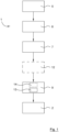
- figure 1 disclose a schematic illustration of a generic production line/apparatus for dry manufacturing rigid cellulose products, wherein said apparatus is generally designated 1.
- the production line 1 is configured for manufacturing rigid cellulose products, generally designated 2, having essentially non-flat general shape from separated cellulose fibres.
- Such a production line 1 may be arranged and set-up according to different well-known ways.
- Figure 10 disclose a rigid cellulose tray 2 having at least two compartments 3a, 3b separated by a partition 4.
- the apparatus 1 may have automized transfer/handling between the different process steps, and/or may have manual transfer/handling between the different process steps, and thereto the apparatus 1 may have intermediate storing and/or additional process steps between the disclosed process steps.
- Cellulose raw material 5 i.e. comprising mainly of the cellulose part of organic matter
- a separating/disintegrating unit 6 in order to obtain individualized/separated cellulose fibres.
- the separated cellulose fibres are thereafter transported by an air stream/flow to a dispenser of a cellulose blank/sheet forming unit 7.
- the cellulose fibres are laid by the dispenser on a moving or stationary perforated surface of the cellulose blank forming unit 7.
- the cellulose fibre carrying air flow may be generated by suitable device located upstream and/or downstream the perforated surface.
- the generated cellulose blank generally designated 8 is transported to a product forming unit 9, whereby rigid cellulose products/trays 2 are formed and discharged from the product forming unit 9.
- the cellulose blank forming unit 7 may be configured to generate a continuous cellulose blank/web and/or discontinuous/discrete cellulose blanks. Discontinuous/discrete cellulose blanks are fed into the product forming unit 9.
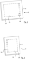
- Figure 2 disclose a first cellulose blank segment 10 and figure 3 disclose a second cellulose blank segment 11, which both are made of a cellulose blank 8.
- the first cellulose blank segment 10 and the second cellulose blank segment 11 may have the same or different size.
- the cellulose raw material 5 may be in the form of reeled pulp or paper, bale of cellulose pulp, paper, etc. and/or sheets of paper, cellulose pulp, etc. In case said cellulose raw material 5 is in the form of sheets and/or reeled pulp or paper, it can be fed directly into the separating unit 6. However, in case said cellulose raw material 5 is in the form of a bale or compact stacks of sheets, etc. one or more shredders and/or one or more additional separating/disintegrating units 6 may be necessary to be used for separating and dosing said cellulose raw material 5 from said bale or sheets in smaller quantities. The shredder(s) prepare cellulose raw material 5 to be accepted by said separating unit 6.
- the separating unit 6 disintegrates the cellulose raw material 5 into separated cellulose fibres.
- Said one or plurality of shredder(s) are arranged before said one or a plurality of separating unit(s) 6, so that an output of one of said shredder is connected to an input of one of said separating units 6.
- the shredders may be arranged in parallel to each other or in series with each other, and the disintegrating units 6 may be arranged in parallel to each other or in series with each other.
- the shredders and the disintegrating units 6 together constitute a cellulose fibre separating unit, arranged upstream the cellulose blank forming unit 7.
- Said cellulose raw material 5 may be constituted by virgin cellulose fibres and/or recycled cellulose fibres and may originate from wood pulps such as kraft pulp, sulphite pulp, mechanical pulp, thermomechanical pulp (TMP), chemical treated mechanical pulp, chemi-thermomechanical pulp (CTMP), and/or from non-wood pulps such as bagasse, bamboo, abaca, hemp, flax, cotton.
- wood pulps such as kraft pulp, sulphite pulp, mechanical pulp, thermomechanical pulp (TMP), chemical treated mechanical pulp, chemi-thermomechanical pulp (CTMP), and/or from non-wood pulps such as bagasse, bamboo, abaca, hemp, flax, cotton.
- the separating unit 6 may according to various embodiments be constituted by a hammer mill.
- said separating unit 6 the cellulose raw material is separated into fibres having a normal length in the range of 0,5-70 mm, preferably less than 10 mm.
- the length of said fibres may be customized by adjusting the internal properties of the separating unit 6 and/or by choosing a different separating unit 6 and/or choosing different cellulose raw material.
- the fibre length for wood pulp is according to various embodiments in the range 0,5-4 mm, preferably in the range 1,7-3,6 mm.
- the fibre length for non-wood pulp is in the range 0,5-70 mm.
- the production line 1 may comprise a pre-compression and/or imprinting unit 12, located downstream the cellulose blank forming unit 7 and upstream the product forming unit 9.
- a pre-compression and/or imprinting unit 12 located downstream the cellulose blank forming unit 7 and upstream the product forming unit 9.
- an air-laid fluffy cellulose blank 8 having a first thickness may be compressed into a cellulose blank 8 having a second thickness, wherein said second thickness is thinner than said first thickness, and/or may be provided with an imprinting pattern.
- the cellulose blank is made more coherent and easier to handle, since the pre-compression/imprinting generates internal bindings between individual cellulose fibres preventing mutual separation of the cellulose fibres.
- the product forming unit 9 comprises a press unit 13, and may optionally comprise a pre-heating unit 14 arranged upstream the press unit 13.
- said cellulose blank 8 may be heated to an elevated temperature before being fed into the press unit 13 of the product forming unit 9.
- said press unit 13 may or may not comprise heating.
- said press unit 13 may be a heated press unit 13 for heating said cellulose blank 8 during pressing.
- preheating of said cellulose blank 8 using a pre-heating unit 14 is optional.
- preheating of the cellulose blank 8 in said pre-heating unit 14 may be combined with a heated press unit 13.
- Having a pre-heating unit 14 in combination with a heated press unit 13 will speed up the manufacturing process in the product forming unit 9, and improve the quality/rigidity of the final rigid cellulose product/tray 2.
- the cellulose blank 8 is heated to a temperature in the range 120 - 200 °C in order to obtain adequate rigidity and strength in the final cellulose product/tray 2.
- Figure 2 disclose a first type of cellulose blank 8 constituted by a first cellulose blank segment 10
- figure 3 disclose a second type of cellulose blank 8 constituted by a second cellulose blank segment 11.
- the first cellulose blank segment 10 and the second cellulose blank segment 11 may be of the same type or of different type, i.e. regarding surface weight, material, thickness, size, general shape, etc.
- the first cellulose blank segment 10 comprises a first sub-tray area 15 and a bridging area 16 located adjacent the first sub-tray area 15. Outside the first sub-tray area 15 and the associated bridging area 16, the first cellulose blank segment 10 may comprise a scrap/residual area 17.
- the second cellulose blank segment 11 comprises a second sub-tray area 18 and a bridging area 19 located adjacent the second sub-tray area 18. Outside the second sub-tray area 18 and the associated bridging area 19, the second cellulose blank segment 11 may comprise a scrap/residual area 20.
- Said scrap areas 17, 20 are preferably as small as possible in order to minimize scrap from the product forming unit 9.
- the press unit 13 comprises a first moulding tool having a first mould part 21 and a second mould part 22 having co-operating designs, wherein at least one of the first mould part 21 and the second mould part 22 is/are displaceable in the axial direction in relation to each other, i.e. reciprocating back and forth in relation to each other, in order to exert pressure to the cellulose blank 8 loaded therebetween.
- the mutual displacement is disclosed as being vertical, however the mutual displacement may be horizontal or any other suitable angle.
- the cellulose blank 8 loaded into the first moulding tool is constituted by the air-laid first cellulose blank segment 10.
- the air-laid first cellulose blank segment 10 may be generated upstream the product forming unit 9 in the same apparatus/production line and provided/transferred to the product forming unit 9, or may be generated at a separate location and provided/transferred to the product forming unit 9 via intermediate handling and storage.
- the first mould part 21 of the first moulding tool is a female mould part, i.e. having a recess 23 for receiving the first sub-tray area 15 of the first cellulose blank segment 10
- the second mould part 22 of the first moulding tool is a male mould part, i.e. having a protrusion 24 for cooperation with said recess 23, such that the first sub-tray area 15 of the first cellulose blank segment 10 is pressed into a final rigid non-flat shape, i.e. a first sub-tray of any conceivable shape.
- the female mould part 21 is located above the male mould part 22, but according to alternative embodiments the male mould part 22 may be located above the female mould part 21.
- first sub-tray area 15 of the first cellulose blank segment 10 obtains its final rigid non-flat shape, which may have any conceivable tray design/shape.
- the main projection 24 of the male mould part 22 has a bottom surface 25 and a wall surface 26 connected to the bottom surface 25 and extending essentially in the axial direction.
- the main recess 23 of the female mould part 21 has a bottom surface 27 and a wall surface 28 connected to the bottom surface 27 and extending essentially in the axial direction.
- the first sub-tray area 15 of the first cellulose blank segment 10 is pressed between the surfaces of the male mould part 22 and the surfaces of the female mould part 21 into final shape. During the pressing of the first sub-tray area 15 of the first cellulose blank segment 10, the bridging area 16 of the first cellulose blank segment 10 is kept in a non-final non-rigid shape, i.e.
- the first mould part 21 and/or the second mould part 22 comprise(s) local recesses 29 adjacent the recess 23 and/or the projection 24.
- Such local recesses 29 in the mould parts entails that the mutual distance between the surfaces of the first mould part 21 and the second mould part 22 at the first sub-tray area 15 is less than the mutual distance between the surfaces of the first mould part 21 and the second mould part 22 at the bridging area 16, whereby the bridging area 16 is un-compressed or only partially compressed when the first sub-tray area 15 is pressed/formed.
- the mutual distance at the bridging area 16 is preferably equal to or more than 20 % greater than the mutual distance at the first sub-tray area 15, and preferably equal to or less than 100 % greater than the mutual distance at the first sub-tray area 15.
- the mutual distance between the first mould part 21 and the second mould part 22 is equal to or more than the mutual distance at the first sub-tray area 15.
- the scrap area 17 may be left entirely uncompressed, be partially compressed by applying for instance the predetermined forth pressure P4 or be fully compressed by applying for instance the predetermined first pressure P1.
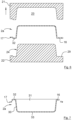
- FIG 6 the first cellulose blank segment 10 is released by opening the first moulding tool, wherein the first sub-tray area 15 is pressed into final rigid non-flat shape and the bridging area 16 is kept in a non-final non-rigid shape.
- Figure 7 disclose a schematic illustration of a first sub-tray 2a wherein the scrap area 17 is removed from the first sub-tray 2a.
- the scrap area 17 may be removed in a separate step in the first moulding tool, in a subsequent step outside the first moulding tool, or in a step concurrent with the pressing of the first sub-tray 2a.
- the first sub tray 2a comprises a circumferential wall 30 and an opening 31 defined by a circumferential rim/brim 32 located at the upper/free end of the wall 30.
- the brim 32 has an angled shape having an essentially radially extending upper surface and a turned-down outer edge, however it shall be pointed out that the cross-section of the brim 32 may have other shapes.
- the first sub tray 2a may have truncated cone shape having straight wall 30, narrowing in the direction away from the opening 31, in accordance with figure 7 embodiment, or may for instance have curved-shaped wall 30 seen in the axial plane. Thereby multiple such first sub trays 2a are stackable one inside the other when they are empty.
- the cross section of the wall 30 in the radial plane may have any suitable shape, circular, oval, rectangular, polygonal, etc., and may differ in shape and/or dimension along the axial extension of the first sub tray 2a.
- the first sub tray 2a comprise a bottom portion 33, wherein the bottom portion is flat or the bottom may comprise local ribs, projections, etc., for strength and rigidity of the cellulose product.
- the bottom 33 may be located at the very lower end of the wall 30, according to figure 7 embodiment, or be located at a distance from the lower end of the wall 30, or a combination thereof.
- the circumferential wall 30 is connected to and extends in the axial direction upwards from the bottom portion 33.
- the walls of the moulding tool has to be inclined in order to obtain a release angle for the cellulose product, and in order to obtain adequate press force to the wall region of the cellulose product.
- the invention comprises various embodiments, but common for all embodiments is that a second cellulose blank segment 11 is loaded into a second moulding tool that is part of the press unit 13. It shall be pointed out that the second moulding tool does not need to be arranged at the same location as the first moulding tool. It shall also be pointed out that the second moulding tool may be constituted by the first moulding tool, or by a moulding tool of the same type/design as said first moulding tool.
- the second sub-tray area 18 of the second cellulose blank segment 11 is pressed into a final rigid shape by applying a predetermined second pressure P2.
- the predetermined second pressure P2 is preferably equal to the predetermined first pressure P1.
- the second moulding tool is identical to, or is constituted by, the first moulding tool. Nonetheless, the same steps are performed mutatis mutandis in order to generate the second sub-tray 2b having a pressed second sub-tray area 18 as described above to generate the first sub-tray 2a.
- the bridging area 19 of the second sub-tray 2b is kept/maintained in a non-final non-rigid shape.
- the bridging area 19 of the second cellulose blank segment 11 is partially compressed into a non-final non-rigid shape, it is performed by applying a predetermined fifth pressure P5, wherein P5 ⁇ P2.
- the second sub-tray 2b comprises a bottom portion 34 and a circumferential wall 35 connected to and extending in the axial direction upwards from the bottom portion 34.
- the second sub-tray 2b also comprises an opening 36 defined by a circumferential rim/brim 37 located at the upper/free end of the wall 35.
- the compartments 3a, 3b are open upwards in order to receive objects/items.
- FIGS 8-9 disclose a third moulding tool having a first mould part 38 and a second mould part 39, wherein the third moulding tool is part of the pressing unit 13.
- the third moulding tool is configured to join together the bridging area 16 of the first cellulose blank segment 10 and the bridging area 19 of the second cellulose blank segment 11 into a final rigid partition 4 by applying a predetermined third pressure P3, thereby obtaining the rigid cellulose tray 2 having at least two compartments 3a, 3b separated by the partition 4.
- the predetermined third pressure P3 is preferably greater than the predetermined first pressure P1. It shall be pointed out that only parts of the third moulding tool is disclosed in figures 8-9 , for instance the third moulding tool comprises a support (non-disclosed) for the first sub-tray 2a and the second sub-tray 2b.
- the first cellulose blank segment 10 having pre-pressed first sub-tray area 15 and the second cellulose blank segment 11 having pre-pressed second sub-tray area 18 are introduced/loaded in the third moulding tool.
- the bridging area 16 of the first cellulose blank segment 10 is placed in overlapping contact with the bridging area 19 of the second cellulose blank segment 11, and the first sub-tray 2a of the first cellulose blank segment 10 is placed besides the second sub-tray 2b of the second cellulose blank segment 11, i.e. the first sub-tray 2a is separated from the second sub-tray 2b by said overlapping bridging areas 16, 19.
- the first mould part 38 and the second mould part 39 correspond in shape and location to the bridging area 16 of the first cellulose blank segment 10 and of the bridging area 19 of the second cellulose blank segment 11.
- a liquid composition comprising cellulose or starch may be applied to at least one of the bridging area 16 of the first cellulose blank segment 10 and the bridging area 19 of the second cellulose blank segment 11.
- the liquid composition is preferably constituted by cellulose fibres that are wetted/dampened by water.
- only water is applied to at least one of the bridging area 16 of the first cellulose blank segment 10 and the bridging area 19 of the second cellulose blank segment 11.
- FIG. 10 disclosing a rigid cellulose tray 2 from above.
- the partition 4 is a straight line, however the partition may have any suitable shape such as curved, wave-shaped.
- the rigid cellulose tray 2 may have a rectangular shape as in the disclosed embodiment, or may have any suitable shape such as circular, polygonal, etc.
- the cellulose tray 2 comprises three compartments 3a, 3b and 3c, i.e.
- the rigid cellulose tray 2 may comprise more than two compartments, wherein each pair of bridging areas are joined as described above.
- a third sub-tray 2c is pre-pressed in the same way as the first sub-tray 2a and all three pre-pressed sub-trays are joined in the third moulding tool.
- the partition 4 may comprise one or more folding groove(s)/notch(es) extending along the partition such that the second sub-tray 2b may be easily folded in relation to the first sub-tray 2a, for instance in order to mix the second item 41 with the first item 40.
- the partition 4 may comprise a perforation line extending along the partition such that the first sub-tray 2a and the second sub-tray 2b can be separated from each other by tearing at the perforation line.
- the partition 4 is preferably equal to or more than 5 millimetres and equal to or less than 20 millimetres, preferably equal to or less than 10 millimetres.
- the width of the partition 4 is measured as the width of the overlapping part before joining of the bridging areas.
- a film/cover/lid may be attached to the circumferential rim/brim of the cellulose tray 2 and to the partition 4, for instance using heat lamination.
- the lid film may be constituted by a multilayer film comprising polymer, metal, and/or paper.
- the rigid cellulose tray 2 Before any items are placed in the compartments of the rigid cellulose tray, the rigid cellulose tray 2 may be provided with a liner film adhered to at least to the circumferential rim/brim and to the partition(s), and preferably also to the walls and/or bottom of the sub-trays.
- the liner film may be constituted by a multilayer film comprising polymer and/or metal. The adhesion of the liner film to the tray is preferably heat activated.
- the cellulose blanks may comprise barrier additives, such that the rigid cellulose tray 2 withstand grease, fat, water, vapour, etc.
- the predetermined pressures P1-P5 is in the range 40-10000N/cm 2 , preferably in the range 100-4000N/cm 2 . According to various embodiments said predetermined pressures are above 1000 N/ cm 2 , and according to various embodiments said predetermined pressures are below 2500 N/ cm 2 .
- the holding time during the different pressing steps is in equal to or more than 1 second and equal to or less than 10 seconds, preferably less than 5 seconds, and most preferably less than 3 seconds.
- the final rigid cellulose product may be constituted by three or more segments, wherein each pair of neighbouring segments are joined/connected to each other according to the present invention.
Landscapes
- Engineering & Computer Science (AREA)
- Life Sciences & Earth Sciences (AREA)
- Manufacturing & Machinery (AREA)
- Wood Science & Technology (AREA)
- Forests & Forestry (AREA)
- Mechanical Engineering (AREA)
- Ceramic Engineering (AREA)
- Containers Having Bodies Formed In One Piece (AREA)
Priority Applications (2)
| Application Number | Priority Date | Filing Date | Title |
|---|---|---|---|
| EP23215964.0A EP4570488A1 (de) | 2023-12-12 | 2023-12-12 | Verfahren und vorrichtung zur trockenherstellung einer steifen zelluloseschale und steife zelluloseschale |
| PCT/EP2024/085397 WO2025125192A1 (en) | 2023-12-12 | 2024-12-10 | Method and apparatus for dry manufacturing rigid cellulose tray and rigid cellulose tray |
Applications Claiming Priority (1)
| Application Number | Priority Date | Filing Date | Title |
|---|---|---|---|
| EP23215964.0A EP4570488A1 (de) | 2023-12-12 | 2023-12-12 | Verfahren und vorrichtung zur trockenherstellung einer steifen zelluloseschale und steife zelluloseschale |
Publications (1)
| Publication Number | Publication Date |
|---|---|
| EP4570488A1 true EP4570488A1 (de) | 2025-06-18 |
Family
ID=89222425
Family Applications (1)
| Application Number | Title | Priority Date | Filing Date |
|---|---|---|---|
| EP23215964.0A Pending EP4570488A1 (de) | 2023-12-12 | 2023-12-12 | Verfahren und vorrichtung zur trockenherstellung einer steifen zelluloseschale und steife zelluloseschale |
Country Status (2)
| Country | Link |
|---|---|
| EP (1) | EP4570488A1 (de) |
| WO (1) | WO2025125192A1 (de) |
Citations (4)
| Publication number | Priority date | Publication date | Assignee | Title |
|---|---|---|---|---|
| US4832676A (en) * | 1986-12-08 | 1989-05-23 | James River-Norwalk, Inc. | Method and apparatus for forming paperboard containers |
| GB2449507A (en) * | 2007-07-25 | 2008-11-26 | Procurasell Holdings Ltd | Method and apparatus for manufacturing a food packaging container |
| EP1511676B1 (de) * | 2002-06-07 | 2008-11-26 | Ipack S.r.l. | Verfahren zur herstellung von schalen mit mehreren kammern und damit hergestellte schale |
| US8741443B2 (en) * | 2011-05-18 | 2014-06-03 | Powertray, LLC | Disposable food tray |
-
2023
- 2023-12-12 EP EP23215964.0A patent/EP4570488A1/de active Pending
-
2024
- 2024-12-10 WO PCT/EP2024/085397 patent/WO2025125192A1/en active Pending
Patent Citations (4)
| Publication number | Priority date | Publication date | Assignee | Title |
|---|---|---|---|---|
| US4832676A (en) * | 1986-12-08 | 1989-05-23 | James River-Norwalk, Inc. | Method and apparatus for forming paperboard containers |
| EP1511676B1 (de) * | 2002-06-07 | 2008-11-26 | Ipack S.r.l. | Verfahren zur herstellung von schalen mit mehreren kammern und damit hergestellte schale |
| GB2449507A (en) * | 2007-07-25 | 2008-11-26 | Procurasell Holdings Ltd | Method and apparatus for manufacturing a food packaging container |
| US8741443B2 (en) * | 2011-05-18 | 2014-06-03 | Powertray, LLC | Disposable food tray |
Also Published As
| Publication number | Publication date |
|---|---|
| WO2025125192A1 (en) | 2025-06-19 |
Similar Documents
| Publication | Publication Date | Title |
|---|---|---|
| RS62828B1 (sr) | Postupak za proizvodnju proizvoda od celuloze, uređaj za oblikovanje proizvoda od celuloze i proizvod od celuloze | |
| WO2025125192A1 (en) | Method and apparatus for dry manufacturing rigid cellulose tray and rigid cellulose tray | |
| EP4477373A1 (de) | Verfahren und vorrichtung zur trockenherstellung von steifen zelluloseprodukten | |
| EP4678363A1 (de) | Verfahren und vorrichtung zur trockenherstellung von steifen zelluloseprodukten | |
| EP4650161A1 (de) | Verfahren und produktformungseinheit zur trockenherstellung von steifen celluloseprodukten | |
| EP4527610A1 (de) | Vorrichtung und verfahren zur trockenherstellung von steifen zelluloseprodukten | |
| EP4520496A1 (de) | Vorrichtung zur trockenherstellung von steifen zelluloseprodukten | |
| EP4477575A1 (de) | Verpackungsbehälter | |
| EP4527608A1 (de) | Vorrichtung und verfahren zur trockenherstellung von steifen zelluloseprodukten | |
| EP4733023A1 (de) | Produktformungseinheit zur trockenherstellung von starren celluloseprodukten und verfahren zur steuerung solch einer produktformungseinheit | |
| WO2026104522A1 (en) | Product forming unit for dry manufacturing rigid cellulose products | |
| EP4613472A1 (de) | Produktformungseinheit zur trockenherstellung von starren celluloseprodukten und verfahren zur steuerung solch einer produktformungseinheit | |
| EP4640392A1 (de) | Produktformungseinheit zur trockenherstellung von starren celluloseprodukten | |
| EP4656369A1 (de) | Produktformungseinheit und verfahren zur trockenherstellung von starren celluloseprodukten | |
| EP4656368A1 (de) | Produktformungseinheit und verfahren zur trockenherstellung von starren celluloseprodukten | |
| EP4467480A1 (de) | Deckel zur verwendung zusammen mit einem behälter sowie satz aus behälter und deckel und verfahren zur herstellung solch eines deckels | |
| WO2026041583A1 (en) | Product forming unit and method for dry manufacturing rigid cellulose products | |
| WO2026104520A1 (en) | Method for dry manufacturing rigid cellulose products | |
| EP4653184A1 (de) | Vorrichtung und verfahren zur trockenherstellung von steifen zelluloseprodukten | |
| WO2026104521A1 (en) | Method for dry manufacturing rigid cellulose products | |
| EP4733024A1 (de) | Produktformungseinheit zur trockenherstellung von starren celluloseprodukten und verfahren zur steuerung solch einer produktformungseinheit | |
| WO2025132692A1 (en) | Multi-cavity forming mould system and method for dry-forming cellulose products in a multi-cavity forming mould system | |
| WO2025132690A1 (en) | A method for producing a cellulose product and a cellulose product | |
| WO2025056529A1 (en) | Method of producing fiber product from natural fibers using pressure and vibration | |
| WO2024245665A1 (en) | Method for dry-forming a cellulose product from cellulose fibres in a product forming unit and a product forming unit |
Legal Events
| Date | Code | Title | Description |
|---|---|---|---|
| PUAI | Public reference made under article 153(3) epc to a published international application that has entered the european phase |
Free format text: ORIGINAL CODE: 0009012 |
|
| STAA | Information on the status of an ep patent application or granted ep patent |
Free format text: STATUS: THE APPLICATION HAS BEEN PUBLISHED |
|
| AK | Designated contracting states |
Kind code of ref document: A1 Designated state(s): AL AT BE BG CH CY CZ DE DK EE ES FI FR GB GR HR HU IE IS IT LI LT LU LV MC ME MK MT NL NO PL PT RO RS SE SI SK SM TR |
|
| STAA | Information on the status of an ep patent application or granted ep patent |
Free format text: STATUS: REQUEST FOR EXAMINATION WAS MADE |
|
| 17P | Request for examination filed |
Effective date: 20251203 |