EP4570517A1 - Radialer luftreifen für personenkraftwagen - Google Patents
Radialer luftreifen für personenkraftwagen Download PDFInfo
- Publication number
- EP4570517A1 EP4570517A1 EP23852209.8A EP23852209A EP4570517A1 EP 4570517 A1 EP4570517 A1 EP 4570517A1 EP 23852209 A EP23852209 A EP 23852209A EP 4570517 A1 EP4570517 A1 EP 4570517A1
- Authority
- EP
- European Patent Office
- Prior art keywords
- tire
- carcass
- width
- cross
- tag
- Prior art date
- Legal status (The legal status is an assumption and is not a legal conclusion. Google has not performed a legal analysis and makes no representation as to the accuracy of the status listed.)
- Pending
Links
Images




Classifications
-
- B—PERFORMING OPERATIONS; TRANSPORTING
- B60—VEHICLES IN GENERAL
- B60C—VEHICLE TYRES; TYRE INFLATION; TYRE CHANGING; CONNECTING VALVES TO INFLATABLE ELASTIC BODIES IN GENERAL; DEVICES OR ARRANGEMENTS RELATED TO TYRES
- B60C9/00—Reinforcements or ply arrangement of pneumatic tyres
- B60C9/02—Carcasses
- B60C9/04—Carcasses the reinforcing cords of each carcass ply arranged in a substantially parallel relationship
- B60C9/08—Carcasses the reinforcing cords of each carcass ply arranged in a substantially parallel relationship the cords extend transversely from bead to bead, i.e. radial ply
-
- B—PERFORMING OPERATIONS; TRANSPORTING
- B60—VEHICLES IN GENERAL
- B60C—VEHICLE TYRES; TYRE INFLATION; TYRE CHANGING; CONNECTING VALVES TO INFLATABLE ELASTIC BODIES IN GENERAL; DEVICES OR ARRANGEMENTS RELATED TO TYRES
- B60C9/00—Reinforcements or ply arrangement of pneumatic tyres
- B60C9/02—Carcasses
- B60C9/04—Carcasses the reinforcing cords of each carcass ply arranged in a substantially parallel relationship
-
- B—PERFORMING OPERATIONS; TRANSPORTING
- B60—VEHICLES IN GENERAL
- B60C—VEHICLE TYRES; TYRE INFLATION; TYRE CHANGING; CONNECTING VALVES TO INFLATABLE ELASTIC BODIES IN GENERAL; DEVICES OR ARRANGEMENTS RELATED TO TYRES
- B60C13/00—Tyre sidewalls; Protecting, decorating, marking, or the like, thereof
- B60C13/003—Tyre sidewalls; Protecting, decorating, marking, or the like, thereof characterised by sidewall curvature
-
- B—PERFORMING OPERATIONS; TRANSPORTING
- B60—VEHICLES IN GENERAL
- B60C—VEHICLE TYRES; TYRE INFLATION; TYRE CHANGING; CONNECTING VALVES TO INFLATABLE ELASTIC BODIES IN GENERAL; DEVICES OR ARRANGEMENTS RELATED TO TYRES
- B60C15/00—Tyre beads, e.g. ply turn-up or overlap
- B60C15/0009—Tyre beads, e.g. ply turn-up or overlap features of the carcass terminal portion
-
- B—PERFORMING OPERATIONS; TRANSPORTING
- B60—VEHICLES IN GENERAL
- B60C—VEHICLE TYRES; TYRE INFLATION; TYRE CHANGING; CONNECTING VALVES TO INFLATABLE ELASTIC BODIES IN GENERAL; DEVICES OR ARRANGEMENTS RELATED TO TYRES
- B60C15/00—Tyre beads, e.g. ply turn-up or overlap
- B60C15/0009—Tyre beads, e.g. ply turn-up or overlap features of the carcass terminal portion
- B60C15/0027—Tyre beads, e.g. ply turn-up or overlap features of the carcass terminal portion with low ply turn-up, i.e. folded around the bead core and terminating at the bead core
-
- B—PERFORMING OPERATIONS; TRANSPORTING
- B60—VEHICLES IN GENERAL
- B60C—VEHICLE TYRES; TYRE INFLATION; TYRE CHANGING; CONNECTING VALVES TO INFLATABLE ELASTIC BODIES IN GENERAL; DEVICES OR ARRANGEMENTS RELATED TO TYRES
- B60C3/00—Tyres characterised by the transverse section
- B60C3/04—Tyres characterised by the transverse section characterised by the relative dimensions of the section, e.g. low profile
-
- B—PERFORMING OPERATIONS; TRANSPORTING
- B60—VEHICLES IN GENERAL
- B60C—VEHICLE TYRES; TYRE INFLATION; TYRE CHANGING; CONNECTING VALVES TO INFLATABLE ELASTIC BODIES IN GENERAL; DEVICES OR ARRANGEMENTS RELATED TO TYRES
- B60C3/00—Tyres characterised by the transverse section
- B60C3/06—Tyres characterised by the transverse section asymmetric
-
- B—PERFORMING OPERATIONS; TRANSPORTING
- B60—VEHICLES IN GENERAL
- B60C—VEHICLE TYRES; TYRE INFLATION; TYRE CHANGING; CONNECTING VALVES TO INFLATABLE ELASTIC BODIES IN GENERAL; DEVICES OR ARRANGEMENTS RELATED TO TYRES
- B60C9/00—Reinforcements or ply arrangement of pneumatic tyres
- B60C9/02—Carcasses
- B60C9/17—Carcasses asymmetric to the midcircumferential plane of the tyre
-
- B—PERFORMING OPERATIONS; TRANSPORTING
- B60—VEHICLES IN GENERAL
- B60C—VEHICLE TYRES; TYRE INFLATION; TYRE CHANGING; CONNECTING VALVES TO INFLATABLE ELASTIC BODIES IN GENERAL; DEVICES OR ARRANGEMENTS RELATED TO TYRES
- B60C15/00—Tyre beads, e.g. ply turn-up or overlap
- B60C15/0009—Tyre beads, e.g. ply turn-up or overlap features of the carcass terminal portion
- B60C2015/009—Height of the carcass terminal portion defined in terms of a numerical value or ratio in proportion to section height
-
- B—PERFORMING OPERATIONS; TRANSPORTING
- B60—VEHICLES IN GENERAL
- B60C—VEHICLE TYRES; TYRE INFLATION; TYRE CHANGING; CONNECTING VALVES TO INFLATABLE ELASTIC BODIES IN GENERAL; DEVICES OR ARRANGEMENTS RELATED TO TYRES
- B60C2200/00—Tyres specially adapted for particular applications
- B60C2200/04—Tyres specially adapted for particular applications for road vehicles, e.g. passenger cars
Definitions
- This disclosure relates to a pneumatic radial tire for passenger vehicles.
- the applicant has proposed a pneumatic radial tire for passenger vehicles with narrow width and large diameter having a predetermined relationship between the cross-sectional width SW and the outer diameter OD of the tire (e.g., PTL 1).
- the above-mentioned pneumatic radial tire for passenger vehicles with narrow width and large diameter is designed to achieve low fuel consumption, therefore, it is desirable to simplify the structure to further reduce fuel consumption by reducing weight.
- the pneumatic radial tire for passenger vehicles with narrow width and large diameter such as those mentioned above, are often used at high internal pressures, while the rolling resistance is reduced by using them at high internal pressures, there is a concern that ride comfort will deteriorate. Therefore, also from this perspective, it is desirable to simplify the structure in order to reduce the longitudinal spring coefficient.
- an object of the present disclosure is to provide a pneumatic radial tire for passenger vehicles that achieves both high fuel efficiency and cut resistance.
- the gist of the present disclosure is as follows.
- rim refers to the standard rim in the applicable size (Measuring Rim in ETRTO's STANDARDS MANUAL and Design Rim in TRA's YEAR BOOK) as described or as may be described in the future in the industrial standard, which is valid for the area in which the tire is produced and used, such as JATMA YEAR BOOK of JATMA (Japan Automobile Tyre Manufacturers Association) in Japan, STANDARDS MANUAL of ETRTO (The European Tyre and Rim Technical Organization) in Europe, and YEAR BOOK of TRA (The Tire and Rim Association, Inc.) in the United States (That is, the "rim” of the "wheel” mentioned above includes current sizes as well as sizes as described in the future in the aforementioned industrial standards.
- rim refers to a rim with a width corresponding to the bead width of the tire.
- the term “prescribed internal pressure” refers to the air pressure (maximum air pressure) corresponding to the maximum load capacity of a single wheel in the applicable size and ply rating, as described in the aforementioned JATMA YEAR BOOK and other industrial standards. In the case that the size is not listed in the aforementioned industrial standards, the term “prescribed internal pressure” refers to the air pressure (maximum air pressure) corresponding to the maximum load capacity specified for each vehicle in which the tire is mounted.
- maximum load refers to the load corresponding to the maximum load capacity described above.
- a pneumatic radial tire for passenger vehicles comprising
- the "radius of curvature of sidewall portion” shall mean the radius of an arc when the outer contour line of the sidewall portion is approximated by an arc using the least squares method in a cross section in the tire width direction in the above state.
- Figure 1 is a schematic drawing illustrating the cross-sectional width SW and the outer diameter OD of a tire.
- a pneumatic radial tire for passenger vehicles in accordance with one embodiment of the present disclosure (hereinafter, simply referred to as a "tire"), it is preferable that: when the cross-sectional width SW of the tire is less than 165 (mm), a ratio of the cross-sectional width SW to the outer diameter OD of the tire, SW/OD, is 0.26 or less, and when the cross-sectional width SW of the tire is 165 (mm) or more, the cross-sectional width SW (mm) and the outer diameter OD (mm) of the tire satisfy the following relational expression: OD mm ⁇ 2.135 ⁇ SW mm + 282.3 mm (hereinafter, referred to as "Relational expression (1)").
- the cross-sectional width SW of the tire becomes relatively small compared to the outer diameter OD of the tire, which reduces air resistance, and furthermore, the narrower cross-sectional width allows for more space in a vehicle, and in particular, it allows for more space for installing drive components near the inner side of the tire when the tire is mounted on a vehicle.
- the outer diameter OD of the tire becomes relatively large compared to the cross-sectional width SW of the tire, which reduces rolling resistance, and furthermore, the larger diameter of the tire raises the wheel axis, which increases the space under the floor, allowing for more space in the vehicle's trunk and other areas, as well as more space for installing drive components.
- the cross-sectional width SW (mm) and the outer diameter OD (mm) of the tire satisfy the following relational expression: OD mm ⁇ ⁇ 0.0187 ⁇ SW mm 2 + 9.15 ⁇ SW mm ⁇ 380 mm (hereinafter, referred to as "Relational expression (2)”)
- the cross-sectional width SW of the tire becomes relatively small compared to the outer diameter OD of the tire, which reduces air resistance, and furthermore, the narrower cross-sectional width allows for more space in a vehicle, and in particular, it allows for more space for installing drive components near the inner side of the tire when the tire is mounted on a vehicle.
- the outer diameter OD of the tire becomes relatively large compared to the cross-sectional width SW of the tire, which reduces rolling resistance, and furthermore, the larger diameter of the tire raises the wheel axis, which increases the space under the floor, allowing for more space in the vehicle's trunk and other areas, as well as more space for installing drive components.
- the tires it is preferable for the tires to satisfy the ratio, SW/OD, and/or the relational expression (2), or to satisfy the relational expression (1) and/or the relational expression (2).
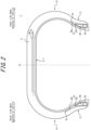
- Figure 2 is a cross-sectional view in the tire width direction of a pneumatic radial tire for passenger vehicles in accordance with one embodiment of the present disclosure.
- Figure 2 illustrates a cross-sectional view in the tire width direction of the tire in a reference condition, with the tire mounted on the rim, filled with the prescribed internal pressure, and unloaded.
- this tire 1 comprises a carcass 3 consisting of a ply/plies made up of radial arrangement cords that straddles in a toroidal shape between a pair of bead portions 2.
- this tire 1 comprises a belt 4 consisting of two belt layers 4a and 4b, in the illustrated example, and a tread 5 in order on the outer side in the tire radial direction of the carcass 3.
- bead cores 2a are embedded in each of the bead portions 2.
- the cross-sectional shape and material of the bead core 2a are not particularly limited, and can be made to have a configuration that is normally used in pneumatic radial tires for passenger vehicles.
- the bead core 2a can be divided into a plurality of small bead cores.
- the bead portion 2 can be configured without a bead core 2a.
- the tire 1 has a bead filler 2b with a roughly triangular cross-section on the outer side in the tire radial direction of the bead core 2a.
- the cross-sectional shape of the bead filler 2b is not limited to this example, and the material is not limited either.
- the tire can be made lighter by omitting the bead filler 2b.
- the tire 1 may also have a rim guard.
- the bead portion 2 can also have additional members such as rubber layers or cord layers for the purpose of reinforcement, etc. These additional members can be provided in various positions relative to the carcass 3 and the bead filler 2b.
- the carcass 3 consists of a single carcass ply.
- the number of carcass plies is not particularly limited, and it can be two or more.
- the carcass 3 has a carcass body portion 3a that extends in a toroidal shape between the pair of bead portions 2, and a carcass turn-up portion 3b that is folded back from the carcass body portion 3a around the bead core 2a.
- the end 3c of the carcass turn-up portion in one tire width-direction half is located on the inner side in the tire radial direction than the end 3c of the carcass turn-up portion in the other tire width-direction half (left side in the drawing).
- the end 3c of the carcass turn-up portion 3b is located on the outer side in the tire radial direction than the tire radially-outer end of the bead filler 2b, and is located on the inner side in the tire radial direction than the tire maximum width position. This makes it possible to reduce the weight of the tire while maintaining the rigidity of the sidewall portion.
- the end 3c of the carcass turn-up portion 3b may be located on the inner side in the tire radial direction than the tire radially-outer end of the bead filler 2b, or it may be located on the outer side in the tire radial direction than the tire maximum width position.
- the carcass may have an envelope structure in which the end 3c of the carcass turn-up portion 3b is located on the inner side in the tire width direction than the end of the belt 4 (for example, the end of the belt layer 4b) so that the end 3c of the carcass turn-up portion 3b is located between the carcass body portion 2a and the belt 4 in the tire radial direction.
- the end 3c of the carcass turn-up portion 3b may be located on the outer side in the tire radial direction than the tire-radially outer end of the bead filler 2b and on the inner side in the tire radial direction than the tire maximum width position in one tire width-direction half, and the end 3c of the carcass turn-up portion 3b may be located on the outer side in the tire radial direction than the tire maximum width position in the other tire width-direction half.
- the position (e.g. the position in the tire radial direction) of the end 3c of the carcass turn-up portion 3b can be the same or different between the carcass plies.
- the number of the carcass cords per unit width in the carcass 3 there is no particular limit to the number of the carcass cords per unit width in the carcass 3, but for example, it may be in the range of 20 to 60 per 50 mm.
- various structures can be adopted for the carcass line.
- the carcass maximum width position can be moved closer to the bead portion 2 side or closer to the tread portion 5 side.
- the carcass maximum width position can be set, from the bead baseline to the outer side in the tire radial direction, in a range of 50% to 90% of the cross-sectional height of the tire.
- the "radial arrangement” mentioned above refers to an arrangement in which the carcass cords extend at an angle of 85° or more, and preferably 90°, to the tire circumferential direction.
- the tire preferably has one or more inclined belt layers made up of a rubber-coated layer of cords that extend at an angle to the tire circumferential direction, and two layers are most preferable in terms of achieving a balance between weight reduction and control of distortion of the shape of the ground contact patch.
- the belt layer can be made one layer, and from the perspective of controlling distortion of the shape of the ground contact patch, it can be made three layers or more.
- the tire widthwise width of the belt layer 4b which is on the outer side in the tire radial direction is smaller than the tire widthwise width of the belt layer 4a which is on the inner side in the tire radial direction.
- the tire widthwise width of the belt layer 4b which is on the outer side in the tire radial direction may be larger than or the same as the tire widthwise width of the belt layer 4a which is on the inner side in the tire radial direction.
- the tire widthwise width of the belt layer having the largest width in the tire width direction is preferably 90 to 115% of the ground contact width, and it is particularly preferable to be 100 to 105 % of the ground contact width.
- the "ground contact width” refers to the distance between the ground contact edges E in the tire width direction.
- the “ground contact edge” refers to the two edges in the tire width direction of the ground contact patch of the tire when the tire is mounted on the rim, filled with the prescribed internal pressure, and loaded with the maximum load.
- the belt cords of the belt layer 4a, 4b it is most preferable to use metal cords, particularly steel cords, but non-metallic cords, for example, organic fiber cords (for example, Kevlar (registered trademark), etc.) can also be used.
- the steel cords are made primarily of steel, and can also contain various trace elements such as carbon, manganese, silicon, phosphorus, sulfur, copper, and chromium.
- the belt cords of the belt layer 4a, 4b may be monofilament cords, cords made of a plurality of filaments aligned in parallel, or cords made of a plurality of filaments twisted together.
- twist structures can be used, and the cross-sectional structure, twist pitch, twist direction, and distance between adjacent filaments can also be varied. Furthermore, cords made of twisted filaments of different materials can also be used, and there are no particular restrictions on the cross-sectional structure, and various twist structures such as single twist, layer twist, and multiple twist can be used.
- the inclination angle of the belt cords in the belt layer 4a, 4b is preferably 10° or more with respect to the tire circumferential direction.
- the inclination angle of the belt cords in the belt layer 4a, 4b is preferably in a high angle, specifically 20° or more and preferably 35° or more with respect to the tire circumferential direction, and particularly in the range of 55° to 85° with respect to the tire circumferential direction. This is because by making the inclination angle 20° or more (preferably 35° or more), the rigidity in the tire width direction can be increased, and the steering stability performance, particularly during cornering, can be improved. In addition, this is because it reduces the rolling resistance by reducing the shear deformation of the interlayer rubber.
- the tread rubber that makes up the tread 5 is composed of a single layer.
- the tread rubber that makes up the tread 5 may be formed by laminating a plurality of rubber layers in the tire radial direction.
- the plurality of rubber layers may have different loss tangents, modulus, hardness, glass transition temperatures, materials, and the like.
- the ratio of the thickness of the plurality of rubber layers in the tire radial direction may vary in the tire width direction, and also, the bottom of the circumferential main groove, etc., may be made of a rubber layer that differs from the surrounding area.
- the tread rubber that makes up the tread 5 may be formed with a plurality of rubber layers that differ in the tire width direction.
- the plurality of rubber layers may have different loss tangents, modulus, hardness, glass transition temperatures, materials, and the like.
- the ratio of the tire widthwise width of the plurality of rubber layers may vary in the tire radial direction, and also, only a limited area, such as only the area near the circumferential main groove, only the area near the ground contact edge, only the shoulder land portion, or only the center land portion, may have a rubber layer that differs from the surrounding area.
- the tire 1 of this embodiment has an inner liner 8 on the inner surface 7 of the tire (simply referred to as the tire inner surface 7).
- the thickness of the inner liner 8 is preferably about 1.5 mm to 2.8 mm. This is because it can effectively reduce the noise inside the car, which is between 80 and 100 Hz.
- the air permeability coefficient of the rubber composition that makes up the inner liner 8 is preferably 1.0 ⁇ 10 -14 cc ⁇ cm/(cm 2 ⁇ s ⁇ cmHg) or more, and 6.5 ⁇ 10 -10 cc ⁇ cm/(cm 2 ⁇ s ⁇ cmHg) or less.
- the pneumatic radial tire for passenger vehicles in this embodiment is a tire in which the cross-sectional width SW and the outer diameter of the tire satisfy the above-mentioned relational expressions (1) and/or (2). According to such tire, air resistance can be reduced in particular, and rolling resistance can also be reduced, so the fuel efficiency of the tire can be improved.
- the end 3c of the carcass turn-up portion 3b in one tire width-direction half that is on the inner side when the tire is mounted on a vehicle is located on the inner side in the tire radial direction than the end 3c of the carcass turn-up portion 3b in the other tire width-direction half that is on the outer side when the tire is mounted on a vehicle.
- the position of the end 3c of the carcass turn-up portion 3b locates relatively on the outer side in the tire radial direction, it is possible to improve the resistance to external damage.
- the tire can be made lighter, rolling resistance can be reduced, and fuel efficiency can be improved.
- the carcass 3 in one tire width-direction half that is on the inner side when the tire is mounted on a vehicle, the carcass 3 is wound around a bead core 2a embedded in the bead portion 2 and terminates therein, and in the other tire width-direction half that is on the outer side when the tire is mounted on a vehicle, the carcass 3 consists of a carcass body portion 3a that straddles in a toroidal shape between the pair of bead portions 2, and a carcass turn-up portions 3b that are folded back from the carcass body portion 3a around bead cores 2a embedded in the bead portions 2, and the end of the carcass 3 in one tire width-direction half that is on the inner side when the tire is mounted on a vehicle is located on the inner side in the tire radial direction than the end 3c of the carcass turn-up portion 3b in the other tire width-direction half that is on the outer side when the tire is mounted on a vehicle.
- the tire can be made lighter, rolling resistance can be reduced, and fuel efficiency can be improved.
- Figure 3 is a cross-sectional view in the tire width direction of a pneumatic radial tire for passenger vehicles in accordance with another embodiment of the present disclosure.
- the tire illustrated in Figure 3 differs from the tire in the embodiment illustrated in Figure 2 in that the shape of the outer contour line of the sidewall portion 8 of the tire differs between one tire width-direction half and the other tire width-direction half.
- a radius of curvature R1 of the sidewall portion 8 in one tire width-direction half on the inner side when the tire is mounted on a vehicle is smaller than a radius of curvature R2 of the sidewall portion 8 on the other tire width-direction half on the outer side when the tire is mounted on a vehicle.
- a radius of curvature CR1 of the carcass in one tire width-direction half on the inner side when the tire is mounted on a vehicle is smaller than a radius of curvature CR2 of the carcass on the other tire width-direction half on the outer side when the tire is mounted on a vehicle.
- the "radius of curvature of carcass” shall mean the radius of an arc when the outer contour line of the carcass is approximated by an arc using the least squares method in a cross section in the tire width direction in the above state.
- the distance in the tire radial direction between a straight line m1, which passes through a point on the tread surface at the tire equatorial plane and is parallel to the tire width direction, and a straight line m2, which passes through the ground contact edge E and is parallel to the tire width direction, is defined as drop height L CR
- the tread width of the tire is defined as TW
- the ratio L CR /TW is greater than 0.045. This allows the crown shape to be relatively round, and thus the shape of the ground contact patch can be made round, with the ground contact length in the shoulder portion shorter than that of the center portion.
- ground contact edge refers to the two edges of the ground contact patch (the part that makes contact with the road surface) of the tire when the tire is mounted on the rim, filled with the prescribed internal pressure, and loaded with the maximum load.
- the "tread width” refers to the distance between the ground contact edges of the tire when the tire is mounted on the rim, filled with the prescribed internal pressure, and unloaded.
- a tire and rim assembly here is formed by mounting the above-mentioned pneumatic radial tire for passenger vehicles on the rim. According to this tire and rim assembly, it is possible to obtain the same effects as those described for the above-mentioned pneumatic radial tire for passenger vehicles.
- the internal pressure of the tire and rim assembly is preferably 200 kPa or more, it is more preferable to be 220 kPa or more, and it is even more preferable to be 280 kPa or more. This is because the rolling resistance can be further reduced by increasing the internal pressure.
- the internal pressure of the tire and rim assembly is preferably 350 kPa or less, as this improves ride comfort.
- the method for using the pneumatic radial tire for passenger vehicles uses the above-mentioned pneumatic radial tire for passenger vehicles. According to the method for using the pneumatic radial tire for passenger vehicles, it is possible to obtain the same effects as those described above for the pneumatic radial tire for passenger vehicles. At this time, it is preferable to use it with an internal pressure of 200 kPa or more, and it is even more preferable to use it with an internal pressure of 220 kPa or more, and it is even more preferable to use it with an internal pressure of 280 kPa or more. This is because the rolling resistance can be further reduced by increasing the internal pressure. On the other hand, it is preferable to use it with an internal pressure of 350 kPa or less, as this improves ride comfort.
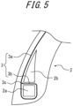
- Figure 4 illustrates the tire width-direction half that comprises a layer.
- the tire may comprise an RF tag as a communication device 500.
- the RF tag has an IC chip and an antenna.
- the RF tag may be arranged, for example, by being sandwiched between a plurality of members of the same type or different types that constitute the tire. In this way, it is easier to attach RF tags when producing tires, and the productivity of tires with RF tags can be improved.
- the RF tag may be arranged between, for example, the bead filler and other members adjacent to the bead filler.
- the RF tag may be embedded in any of the members that constitute the tire.
- the load on the RF tag can be reduced compared to when it is arranged by being sandwiched between a plurality of members that constitute the tire, thereby improving the durability of the RF tag.
- the RF tag may be embedded in rubber members such as tread rubber and side rubber. It is preferable that the RF tag is not arranged at positions that are boundaries between members with different levels of rigidity in a direction of periphery length, which is the direction along the outer surface of the tire when viewed in cross section in the tire width direction. In this way, the RF tag is not arranged in a position where distortion is likely to be concentrated based on the rigidity step. This reduces the load on the RF tag, thereby improving the durability of the RF tag.
- the RF tag is not arranged in a position that is the boundary between, for example, the edge of the carcass and the member (e.g. side rubber, etc.) adjacent to this edge of the carcass when viewed in cross section in the tire width direction.
- the number of RF tags is not limited.
- the tire may have only one RF tag, or it may have two or more.
- an RF tag is described as an example of a communication device, but a communication device other than an RF tag may also be used.
- the RF tag may be arranged, for example, in the tread portion of the tire. In this way, the RF tag will not be damaged by the tire side cut.
- the RF tag may be arranged, for example, in the center of the tread in the tire width direction. The center of the tread is a position where deflection is unlikely to be concentrated in the tread portion. In this way, the load applied on the RF tag can be reduced, thereby improving the durability of the RF tag. This also makes it possible to prevent differences in communication with the RF tag from both outer sides in the tire width direction of the tire.
- the RF tag may be arranged, for example, within a range of 1/2 of the tread width with the tire equatorial plane as the center, in the tire width direction.
- the RF tag may be arranged, for example, at a tread edge portion in the tire width direction. If the position of the reader that communicates with the RF tag is predetermined, the RF tag may be arranged, for example, at the tread edge portion on one side close to this reader. In this example, the RF tag may be arranged, for example, within a range of 1/4 of the tread width, with the tread edge as the outer edge, for example, in the tire width direction.
- the RF tag may be arranged, for example, on the tire inner-cavity side of the carcass including one or more carcass plies straddling between bead portions. In this way, the RF tag becomes less likely to be damaged by external impacts to the tire, or by damage such as side cuts or nail punctures.
- the RF tag may be arranged in close contact with the surface of the carcass facing the inner cavity of the tire.
- the RF tag may be arranged between the carcass and this another member located on the tire inner-cavity side of the carcass.
- This another member that is located on the tire inner-cavity side of the carcass is, for example, an inner liner, which forms the inner surface of the tire.
- the RF tag may be attached to the inner surface of the tire facing the inner cavity of the tire. By attaching the RF tag to the inner surface of the tire, it is easy to attach the RF tag to the tire, and to inspect and replace the RF tag. In other words, the ease of attachment and maintenance of the RF tag can be improved.
- by attaching the RF tag to the inner surface of the tire it is possible to prevent the RF tag from becoming the core of a tire failure, compared to a structure in which the RF tag is embedded inside the tire.
- the RF tag may be arranged between the overlapped carcass plies.
- the RF tag may be arranged, for example, on the outer side in the tire radial direction than a belt including one or more belt ply in the tread portion of the tire.
- the RF tag may be arranged in close contact with the belt on the outer side in the tire radial direction with respect to the belt.
- the RF tag may be arranged in close contact with the reinforcement belt layer on the outer side in the tire radial direction with respect to the reinforcement belt layer.
- the RF tag may be embedded in the tread rubber on the outer side in the tire radial direction than the belt.
- the RF tag By disposing the RF tag in the tread portion of the tire on the outer side than the belt, communication with the RF tag from the outside of the tire in the tire radial direction is less likely to be disturbed by the belt. Therefore, communication with the RF tag from the outside of the tire in the tire radial direction can be improved.
- the RF tag may be arranged, for example, on the inner side in the tire radial direction of the belt in the tread portion of the tire. In this way, the outer side in the tire radial direction of the RF tag is covered by the belt, so the RF tag becomes less likely to be damaged by impacts from the tread surface or by nail punctures.
- the RF tag may be arranged between the belt and the carcass which is located on the inner side in the tire radial direction than the belt in a tread portion of the tire.
- the RF tag may be arranged between any two belt plies in the tread portion of the tire. According to this configuration, the outer side in the tire radial direction of the RF tag is covered by one or more belt plies, so the RF tag becomes less likely to be damaged by impacts or nail punctures from the tread surface.
- the RF tag may be arranged, for example, at the location in the sidewall portion or the bead portion of the tire.
- the RF tag may be arranged, for example, on the sidewall portion or the bead portion on one side that is close to the reader that can communicate with the RF tag. This improves communication between the RF tag and the reader.
- the RF tag may be arranged between the carcass and the side rubber, or between the tread rubber and the side rubber.
- the RF tag may be arranged, for example, between the tire maximum width position and the tread surface position in the tire radial direction.
- the RF tag may be arranged, for example, on the inner side in the tire radial direction than the tire maximum width position. According to this configuration, the RF tag is arranged near the bead portion having high rigidity. This reduces the load applied on the RF tag, thereby improving the durability of the RF tag. As an example, the RF tag may be arranged in a position adjacent to the bead core in the tire radial direction or the tire width direction.
- the RF tag is arranged on the inner side in the tire radial direction than the tire maximum width position and on the outer side in the tire radial direction than the bead core of the bead portion. According to this configuration, the durability of the RF tag can be improved, and the communication between the RF tag and the reader is less likely to be disturbed by the bead core, so the communication performance of the RF tag can be improved.
- the RF tag may be arranged sandwiched between the plurality of rubber members that constitute the side rubber.
- the RF tag may be arranged, for example, sandwiched between the bead filler and the member adjacent to the bead filler. According to this configuration, it is possible to place the RF tag in a position where the strain is less likely to be concentrated due to the disposal of the bead filler. This reduces the load applied on the RF tag, thereby improving the durability of the RF tag.
- the RF tag may be arranged, for example, between the bead filler and the carcass. The part of the carcass where the RF tag is sandwiched between the carcass and the bead filler may be located on the outer side in the tire width direction with respect to the bead filler, or on the inner side in the tire width direction with respect to the same.
- the bead filler may have a portion that is arranged adjacent to the side rubber.
- the RF tag may be arranged sandwiched between the bead filler and the side rubber.
- the bead filler may also have a portion that is arranged adjacent to the rubber chaffer. In such a case, the RF tag may be arranged sandwiched between the bead filler and the rubber chaffer.
- the RF tag may be arranged, for example, sandwiched between the rubber chaffer and the side rubber. According to this configuration, it is possible to place the RF tag in a position where the strain is less likely to be concentrated due to the placement of the rubber chaffer. This reduces the load applied on the RF tag, thereby improving the durability of the RF tag.
- the RF tag may be arranged, for example, sandwiched between the rubber chaffer and the carcass. According to this configuration, it is possible to reduce the load applied on the RF tag due to impact and damage from the rim. Therefore, the durability of the RF tag can be improved.
- the RF tag may be arranged, for example, sandwiched between the wire chaffer and another member that is adjacent to the wire chaffer on the inner side or the outer side in the tire width direction thereof. According to this configuration, the position of the RF tag is less likely to change when the tire is deformed. This reduces the load applied on the RF tag when the tire is deformed, thereby improving the durability of the RF tag.
- the other member that is adjacent to the wire chaffer on the inner side or the outer side in the tire width direction may be a rubber member, such as a rubber chaffer. Also, the other member that is adjacent to the wire chaffer on the inner side or the outer side in the tire width direction may be a carcass.
- a belt reinforcement layer may be provided on the outer side in the tire radial direction of the belt.
- the belt reinforcement layer may be made by continuously spiraling a cord made of polyethylene terephthalate around the tire in the tire circumferential direction.
- the code is made by applying adhesive treatment under a tension of 6.9 ⁇ 10 -2 N/tex or more, and the elastic modulus at a load of 29.4 N measured at 160°C may be 2.5 mN/dtex% or more.
- the belt reinforcement layer may be arranged to cover the entire belt, or it may be arranged to cover only the two ends of the belt.
- the winding density per unit width of the belt reinforcement layer may vary depending on the position in the width direction. According to this configuration, it is possible to reduce road noise and flat spots without reducing high-speed durability.
- the SDGs have been proposed in order to realize a sustainable society.
- One embodiment of this disclosure is considered to be a technology that can contribute to "No. 12_Ensure sustainable consumption and production patterns" and "No. 13_Climate Action”.
Landscapes
- Engineering & Computer Science (AREA)
- Mechanical Engineering (AREA)
- Tires In General (AREA)
Applications Claiming Priority (2)
| Application Number | Priority Date | Filing Date | Title |
|---|---|---|---|
| JP2022126655A JP2024023082A (ja) | 2022-08-08 | 2022-08-08 | 乗用車用空気入りラジアルタイヤ |
| PCT/JP2023/019385 WO2024034225A1 (ja) | 2022-08-08 | 2023-05-24 | 乗用車用空気入りラジアルタイヤ |
Publications (2)
| Publication Number | Publication Date |
|---|---|
| EP4570517A1 true EP4570517A1 (de) | 2025-06-18 |
| EP4570517A4 EP4570517A4 (de) | 2025-11-19 |
Family
ID=89851285
Family Applications (1)
| Application Number | Title | Priority Date | Filing Date |
|---|---|---|---|
| EP23852209.8A Pending EP4570517A4 (de) | 2022-08-08 | 2023-05-24 | Radialer luftreifen für personenkraftwagen |
Country Status (5)
| Country | Link |
|---|---|
| US (1) | US20260021679A1 (de) |
| EP (1) | EP4570517A4 (de) |
| JP (1) | JP2024023082A (de) |
| CN (1) | CN119604417A (de) |
| WO (1) | WO2024034225A1 (de) |
Family Cites Families (9)
| Publication number | Priority date | Publication date | Assignee | Title |
|---|---|---|---|---|
| JPH06135204A (ja) * | 1992-10-23 | 1994-05-17 | Bridgestone Corp | 空気入りタイヤ |
| DE10057385C1 (de) * | 2000-11-18 | 2002-09-12 | Continental Ag | Fahrzeugluftreifen |
| US7669625B2 (en) * | 2006-11-22 | 2010-03-02 | The Goodyear Tire & Rubber Company | Asymmetrical pneumatic tire |
| JP2012236499A (ja) * | 2011-05-11 | 2012-12-06 | Sumitomo Rubber Ind Ltd | 空気入りタイヤ |
| JPWO2012176476A1 (ja) * | 2011-06-22 | 2015-02-23 | 株式会社ブリヂストン | 乗用車用空気入りラジアルタイヤ、該タイヤの使用方法及び、該タイヤを備えるタイヤ・リム組立体 |
| JP2013112131A (ja) * | 2011-11-28 | 2013-06-10 | Yokohama Rubber Co Ltd:The | 空気入りタイヤ |
| JP5997533B2 (ja) * | 2012-07-31 | 2016-09-28 | 株式会社ブリヂストン | 空気入りラジアルタイヤ |
| EP3206888A4 (de) * | 2014-10-16 | 2018-04-11 | Bridgestone Americas Tire Operations, LLC | Reifen mit asymmetrischer karkassenlagenkonstruktion |
| DE102014222303B4 (de) * | 2014-10-31 | 2025-02-20 | Continental Reifen Deutschland Gmbh | Fahrzeugluftreifen mit asymmetrischer Karkasse |
-
2022
- 2022-08-08 JP JP2022126655A patent/JP2024023082A/ja active Pending
-
2023
- 2023-05-24 EP EP23852209.8A patent/EP4570517A4/de active Pending
- 2023-05-24 US US19/100,577 patent/US20260021679A1/en active Pending
- 2023-05-24 WO PCT/JP2023/019385 patent/WO2024034225A1/ja not_active Ceased
- 2023-05-24 CN CN202380052359.0A patent/CN119604417A/zh active Pending
Also Published As
| Publication number | Publication date |
|---|---|
| US20260021679A1 (en) | 2026-01-22 |
| WO2024034225A1 (ja) | 2024-02-15 |
| CN119604417A (zh) | 2025-03-11 |
| EP4570517A4 (de) | 2025-11-19 |
| JP2024023082A (ja) | 2024-02-21 |
Similar Documents
| Publication | Publication Date | Title |
|---|---|---|
| EP4570516A1 (de) | Radialer luftreifen für personenkraftwagen | |
| EP4570517A1 (de) | Radialer luftreifen für personenkraftwagen | |
| EP4570521A1 (de) | Radialer luftreifen für personenkraftwagen | |
| EP4570518A1 (de) | Radialer luftreifen für personenkraftwagen | |
| WO2024185192A1 (ja) | 空気入りタイヤ | |
| EP4438347A1 (de) | Radialer luftreifen für personenkraftwagen | |
| EP4438346B1 (de) | Radialer luftreifen für personenkraftwagen | |
| EP4360911B1 (de) | Radialer luftreifen für personenkraftwagen | |
| EP4357157B1 (de) | Radialer luftreifen für personenkraftwagen | |
| EP4353497B1 (de) | Radialer luftreifen für personenkraftwagen | |
| EP4353496B1 (de) | Radialer luftreifen für personenkraftwagen | |
| EP4223560B1 (de) | Radialer luftreifen für personenkraftwagen | |
| EP4360907B1 (de) | Radialer luftreifen für personenkraftwagen | |
| EP4360912B1 (de) | Radialer luftreifen für personenkraftwagen |
Legal Events
| Date | Code | Title | Description |
|---|---|---|---|
| STAA | Information on the status of an ep patent application or granted ep patent |
Free format text: STATUS: THE INTERNATIONAL PUBLICATION HAS BEEN MADE |
|
| PUAI | Public reference made under article 153(3) epc to a published international application that has entered the european phase |
Free format text: ORIGINAL CODE: 0009012 |
|
| STAA | Information on the status of an ep patent application or granted ep patent |
Free format text: STATUS: REQUEST FOR EXAMINATION WAS MADE |
|
| 17P | Request for examination filed |
Effective date: 20250120 |
|
| AK | Designated contracting states |
Kind code of ref document: A1 Designated state(s): AL AT BE BG CH CY CZ DE DK EE ES FI FR GB GR HR HU IE IS IT LI LT LU LV MC ME MK MT NL NO PL PT RO RS SE SI SK SM TR |
|
| DAV | Request for validation of the european patent (deleted) | ||
| DAX | Request for extension of the european patent (deleted) | ||
| A4 | Supplementary search report drawn up and despatched |
Effective date: 20251017 |
|
| RIC1 | Information provided on ipc code assigned before grant |
Ipc: B60C 9/17 20060101AFI20251013BHEP Ipc: B60C 3/04 20060101ALI20251013BHEP Ipc: B60C 5/00 20060101ALI20251013BHEP Ipc: B60C 13/00 20060101ALI20251013BHEP Ipc: B60C 15/00 20060101ALI20251013BHEP Ipc: B60C 9/08 20060101ALI20251013BHEP |