EP4570532A1 - Luftreifen - Google Patents
Luftreifen Download PDFInfo
- Publication number
- EP4570532A1 EP4570532A1 EP24209871.3A EP24209871A EP4570532A1 EP 4570532 A1 EP4570532 A1 EP 4570532A1 EP 24209871 A EP24209871 A EP 24209871A EP 4570532 A1 EP4570532 A1 EP 4570532A1
- Authority
- EP
- European Patent Office
- Prior art keywords
- tire
- pair
- pneumatic tire
- rim
- portions
- Prior art date
- Legal status (The legal status is an assumption and is not a legal conclusion. Google has not performed a legal analysis and makes no representation as to the accuracy of the status listed.)
- Pending
Links
Images

Classifications
-
- B—PERFORMING OPERATIONS; TRANSPORTING
- B60—VEHICLES IN GENERAL
- B60C—VEHICLE TYRES; TYRE INFLATION; TYRE CHANGING; CONNECTING VALVES TO INFLATABLE ELASTIC BODIES IN GENERAL; DEVICES OR ARRANGEMENTS RELATED TO TYRES
- B60C13/00—Tyre sidewalls; Protecting, decorating, marking, or the like, thereof
- B60C13/002—Protection against exterior elements
-
- B—PERFORMING OPERATIONS; TRANSPORTING
- B60—VEHICLES IN GENERAL
- B60C—VEHICLE TYRES; TYRE INFLATION; TYRE CHANGING; CONNECTING VALVES TO INFLATABLE ELASTIC BODIES IN GENERAL; DEVICES OR ARRANGEMENTS RELATED TO TYRES
- B60C15/00—Tyre beads, e.g. ply turn-up or overlap
- B60C15/0009—Tyre beads, e.g. ply turn-up or overlap features of the carcass terminal portion
-
- B—PERFORMING OPERATIONS; TRANSPORTING
- B60—VEHICLES IN GENERAL
- B60C—VEHICLE TYRES; TYRE INFLATION; TYRE CHANGING; CONNECTING VALVES TO INFLATABLE ELASTIC BODIES IN GENERAL; DEVICES OR ARRANGEMENTS RELATED TO TYRES
- B60C11/00—Tyre tread bands; Tread patterns; Anti-skid inserts
- B60C11/01—Shape of the shoulders between tread and sidewall, e.g. rounded, stepped or cantilevered
-
- B—PERFORMING OPERATIONS; TRANSPORTING
- B60—VEHICLES IN GENERAL
- B60C—VEHICLE TYRES; TYRE INFLATION; TYRE CHANGING; CONNECTING VALVES TO INFLATABLE ELASTIC BODIES IN GENERAL; DEVICES OR ARRANGEMENTS RELATED TO TYRES
- B60C13/00—Tyre sidewalls; Protecting, decorating, marking, or the like, thereof
-
- B—PERFORMING OPERATIONS; TRANSPORTING
- B60—VEHICLES IN GENERAL
- B60C—VEHICLE TYRES; TYRE INFLATION; TYRE CHANGING; CONNECTING VALVES TO INFLATABLE ELASTIC BODIES IN GENERAL; DEVICES OR ARRANGEMENTS RELATED TO TYRES
- B60C15/00—Tyre beads, e.g. ply turn-up or overlap
- B60C15/0009—Tyre beads, e.g. ply turn-up or overlap features of the carcass terminal portion
- B60C15/0036—Tyre beads, e.g. ply turn-up or overlap features of the carcass terminal portion with high ply turn-up, i.e. folded around the bead core and terminating radially above the point of maximum section width
-
- B—PERFORMING OPERATIONS; TRANSPORTING
- B60—VEHICLES IN GENERAL
- B60C—VEHICLE TYRES; TYRE INFLATION; TYRE CHANGING; CONNECTING VALVES TO INFLATABLE ELASTIC BODIES IN GENERAL; DEVICES OR ARRANGEMENTS RELATED TO TYRES
- B60C15/00—Tyre beads, e.g. ply turn-up or overlap
- B60C15/02—Seating or securing beads on rims
-
- B—PERFORMING OPERATIONS; TRANSPORTING
- B60—VEHICLES IN GENERAL
- B60C—VEHICLE TYRES; TYRE INFLATION; TYRE CHANGING; CONNECTING VALVES TO INFLATABLE ELASTIC BODIES IN GENERAL; DEVICES OR ARRANGEMENTS RELATED TO TYRES
- B60C11/00—Tyre tread bands; Tread patterns; Anti-skid inserts
- B60C11/0008—Tyre tread bands; Tread patterns; Anti-skid inserts characterised by the tread rubber
- B60C2011/0016—Physical properties or dimensions
- B60C2011/0025—Modulus or tan delta
-
- B—PERFORMING OPERATIONS; TRANSPORTING
- B60—VEHICLES IN GENERAL
- B60C—VEHICLE TYRES; TYRE INFLATION; TYRE CHANGING; CONNECTING VALVES TO INFLATABLE ELASTIC BODIES IN GENERAL; DEVICES OR ARRANGEMENTS RELATED TO TYRES
- B60C3/00—Tyres characterised by the transverse section
- B60C3/04—Tyres characterised by the transverse section characterised by the relative dimensions of the section, e.g. low profile
Definitions
- the present invention relates to a pneumatic tire that is mounted and used on a rim.
- the present invention has been made in view of the aforementioned circumstances. It is a main object of the present invention to provide a pneumatic tire that can have improved cut resistance.
- the present invention is directed to a pneumatic tire that is mounted and used on a rim.
- the pneumatic tire includes a tread portion having a ground contact surface, and a pair of sidewall portions extending inward in a tire radial direction from both sides of the tread portion in a tire axial direction.
- the rim has a rim diameter RD of 10 to 18 inches.
- the rim has a rim width RW that is 78% to 99% of a cross-sectional width SW of the tire.
- a ratio SH/SW of a cross-sectional height SH of the tire to the cross-sectional width SW is 30% to 45%.
- Each of the pair of sidewall portions has a buttress portion located on an outer side in the tire radial direction.
- a protector protruding outward in the tire axial direction is disposed on at least one of a pair of the buttress portions.
- the pneumatic tire according to the present invention has the above-described configuration and therefore, can have improved cut resistance.
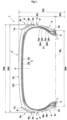
- FIG. 1 is a tire meridional cross-sectional view of a pneumatic tire 1 of the present embodiment in a standardized state.
- the "standardized state” refers to a state in which the pneumatic tire 1 is mounted on a standardized rim and adjusted to be inflated to a standardized internal pressure, and no load is applied to the pneumatic tire 1.
- dimensions of components of the pneumatic tire 1, etc. are represented by values measured in the standardized state.
- the "standardized rim” refers to a rim R that is defined by the standard for each tire, and is, for example, “standard rim” in the JATMA standard, "Design Rim” in the TRA standard, or “Measuring Rim” in the ETRTO standard.
- the "standardized rim” refers to a rim R having the smallest rim width RW among rims R on which the tire can be mounted, and which do not cause air leakage and have the smallest rim diameter RD.
- the "standardized internal pressure” refers to an air pressure that is defined by the standard for each tire, and is “maximum air pressure” in the JATMA standard, the maximum value recited in the table "TIRE LOAD LIMITS AT VARIOUS COLD INFLATION PRESSURES" in the TRA standard, or "INFLATION PRESSURE” in the ETRTO standard.
- the "standardized internal pressure” refers to an air pressure defined for each tire by a manufacturer or the like.
- the pneumatic tire 1 according to the present embodiment is mounted and used on the rim R, has a small diameter, a small ground contact length, and a large ground contact width, and thus has a so-called wide ground contact surface shape.
- the pneumatic tire 1 having such a structure can allow increase in space in a vehicle and space inside the rim, and thus allows, for example, improvement in transport efficiency, use of a large-diameter brake, and upsizing of an in-wheel motor, when used in a small bus, a low-floor electric vehicle, or the like.
- the rim R on which the pneumatic tire 1 according to the present embodiment is mounted has a rim diameter RD of 10 to 18 inches. Since the rim diameter RD is 10 inches or more, a space can be ensured inside the rim. Since the rim diameter RD is 18 inches or less, excessive increase in rim weight and tire weight can be inhibited, resulting in improvement in ride comfort.
- a rim width RW of the rim R is 78% to 99% of a cross-sectional width SW of the tire.
- the rim width RW of the rim R corresponds to a width between a pair of outer surfaces 4s in the tire axial direction, which are located on an inner side, in the tire radial direction, of the pneumatic tire 1 in the standardized state.
- the cross-sectional width SW is a width in the tire axial direction between a pair of tire maximum width positions P in a profile excluding partially protruding portions of the pneumatic tire 1.
- the rim width RW is 78% or more of the cross-sectional width SW, a large volume of a tire inner cavity can be ensured, contributing to improvement in ride comfort. Since the rim width RW is 99% or less of the cross-sectional width SW, a contribution to bearing a heavy load of a small bus, a low-floor electric vehicle, or the like, can be made.
- a ratio SH/SW of a cross-sectional height SH of the tire to the cross-sectional width SW is 30% to 45%.
- the cross-sectional height SH of the tire is a height in the tire radial direction from a bead base line BL to a tire equator C.
- the bead base line BL is an imaginary line corresponding to the rim diameter RD of the rim R.
- the ratio SH/SW is a value commonly known as an aspect ratio.
- the ratio SH/SW is 30% or more, a large volume of the tire inner cavity can be ensured, resulting in improvement in ride comfort. Since the ratio SH/SW is 45% or less, excessive increase in an outer diameter SD of the tire is inhibited, contributing to increase in space in a vehicle such as a small bus or a low-floor electric vehicle.
- the pneumatic tire 1 includes a tread portion 2 having a ground contact surface 2s, and a pair of sidewall portions 3 extending inward in the tire radial direction from both sides of the tread portion 2 in the tire axial direction.
- the pair of sidewall portions 3 each have a buttress portion 3a located on an outer side in the tire radial direction.
- the pneumatic tire 1 preferably includes bead portions 4 located inward of the pair of sidewall portions 3, respectively, in the tire radial direction.
- the outer surface 4s, in the tire axial direction, which is located on the inner side of the pneumatic tire 1 in the tire radial direction is an outer surface 4s of the bead portion 4 in the tire axial direction.
- Each of the pair of bead portions 4 has a ring-shaped bead core 5 extending in the tire circumferential direction, for example.
- the bead core 5 is, for example, formed of a steel wire.
- the pneumatic tire 1 preferably includes a carcass 6 extending from the tread portion 2 to the pair of bead portions 4, and a belt layer 7 provided in the tread portion 2.
- a protector 8 protruding outward in the tire axial direction is disposed in at least one of the pair of buttress portions 3a.
- the protector 8 partially protrudes outward in the tire axial direction from an outer surface 3s that forms a profile of the sidewall portion 3 having the buttress portion 3a, for example.
- the protector 8 is preferably provided at least on the outer surface 3s which is disposed on the outer side of a vehicle when the tire is mounted on the vehicle.
- the protector 8 when the pneumatic tire 1 approaches a curbstone, the protector 8 is brought into contact with the curbstone, thereby inhibiting the outer surface 3s of the sidewall portion 3 and the rim R from coming into contact with the curbstone.
- the protector 8 since the protector 8 is provided on the buttress portion 3a, even when a curbstone is low, contact between the outer surface 3s and the curbstone can be reliably reduced. Therefore, the pneumatic tire 1 according to the present embodiment can have improved cut resistance.
- the protector 8 is provided on each of the pair of buttress portions 3a.
- the protector 8 is preferably provided merely on the buttress portion 3a to be located on the outer side of the vehicle.
- the protector 8 has an outer end 8e that is located outward, in the tire axial direction, of the tire maximum width position P on the outer surface 3s of the sidewall portion 3 excluding the protector 8.
- the protector 8 having such a structure can reliably reduce contact between a curbstone and the sidewall portion 3.
- a total width PW of the tire is a width in the tire axial direction between a pair of the outer ends 8e, and the total width PW is preferably 105% to 115% of the cross-sectional width SW. Since the total width PW is 105% or more of the cross-sectional width SW, contact between a curbstone and the sidewall portion 3 can be reliably reduced, resulting in improvement in cut resistance of the pneumatic tire 1. Since the total width PW is 115% or less of the cross-sectional width SW, excessive increase in side stiffness can be inhibited, so that the pneumatic tire 1 can achieve both cut resistance and ride comfort.
- FIG. 2 is an enlarged cross-sectional view of the sidewall portion 3.
- a protrusion height PH of the protector 8 is preferably 2.0 to 6.0 mm. Since the protrusion height PH is 2.0 mm or more, contact between a curbstone and the sidewall portion 3 can be reliably reduced, resulting in improvement in cut resistance of the pneumatic tire 1. Since the protrusion height PH is 6.0 mm or less, excessive increase in side stiffness can be inhibited, so that the pneumatic tire 1 can achieve both cut resistance and ride comfort.
- the tread portion 2 includes tread rubber 2G that forms the ground contact surface 2s.
- the ground contact surface 2s preferably has a pair of tread ends Te on both sides in the tire axial direction.
- the pair of tread ends Te are each an outermost ground contact position, in the tire axial direction, of the pneumatic tire 1 which is in contact with a plane at a camber angle of 0° with 70% of the standardized load being applied to the pneumatic tire 1 in the standardized state.
- the center position in the tire axial direction between the pair of tread ends Te is the tire equator C.
- the "standardized load” refers to a load that is defined by the standard for each tire, and is "maximum load capacity" in the JATMA standard, the maximum value recited in the table "TIRE LOAD LIMITS AT VARIOUS COLD INFLATION PRESSURES" in the TRA standard, or "LOAD CAPACITY" in the ETRTO standard.
- the "standardized load” refers to a load defined for each tire by a manufacturer or the like as the maximum load that can be applied when the pneumatic tire 1 is used.
- the protector 8 extends inward from the tread end Te in the tire radial direction, for example.
- the protector 8 may, for example, have a shape continuously extending from the tread pattern of the ground contact surface 2s.
- the protector 8 is not limited to such a structure.
- the protector 8 may be provided at any position of the sidewall portion 3 as long as at least a part of the protector 8 is provided on the buttress portion 3a.
- the ratio DH/SH of a height DH of the protector 8 in the tire radial direction to the cross-sectional height SH is preferably 30% to 50%. Since the ratio DH/SH is 30% or more, contact between a curbstone and the sidewall portion 3 can be reliably reduced even during application of a load, resulting in improvement in cut resistance of the pneumatic tire 1. Since the ratio DH/SH is 50% or less, excessive increase in side stiffness can be inhibited, so that the pneumatic tire 1 can achieve both cut resistance and ride comfort.
- the product (DH/SH) ⁇ PH ⁇ Hs of the ratio DH/SH, the protrusion height PH (mm) of the protector 8, and a hardness Hs of the tread rubber 2G is preferably 34 to 201.
- the hardness Hs of the tread rubber 2G is a durometer hardness as measured by using a type A durometer in accordance with JIS-K6253 in an environment of 23°C.
- the pneumatic tire 1 having such a structure is designed so as to reduce the hardness Hs of the tread rubber 2G in a case where the height DH and the protrusion height PH of the protector 8 are large and side stiffness tends to be high, so that the pneumatic tire 1 can achieve both cut resistance and ride comfort.
- the outer diameter SD of the pneumatic tire 1 is preferably 350 to 600 mm. Since the outer diameter SD of the pneumatic tire 1 is 350 mm or more, a space can be ensured inside the rim. Since the outer diameter SD of the pneumatic tire 1 is 600 mm or less, a contribution to increase in space in a vehicle such as a small bus or a low-floor electric vehicle is made.
- the cross-sectional width SW of the pneumatic tire 1 is preferably 145 to 285 mm. Since the cross-sectional width SW is 145 mm or more, a large volume of the tire inner cavity can be ensured, whereby a contribution to improvement in ride comfort is made by the pneumatic tire 1. Since the cross-sectional width SW is 285 mm or less, excessive increase in tire weight is inhibited, whereby the pneumatic tire 1 can maintain high ride comfort.
- the rim width RW of the rim R is preferably 9 inches or less. In the pneumatic tire 1 having such a structure, excessive increase in rim weight can be inhibited, contributing to maintaining high ride comfort.
- the carcass 6 includes at least two carcass plies 6A and 6B.
- the carcass 6 having such a structure can allow exhibition of strength suitable for bearing a heavy load of a small bus, a low-floor electric vehicle, or the like.
- the at least two carcass plies 6A and 6B include, in the tread portion 2, a first carcass ply 6A located on an inner side in the tire radial direction, and a second carcass ply 6B located outward of the first carcass ply 6A in the tire radial direction, for example.
- At least one of the carcass plies 6A and 6B preferably includes a body portion 6a extending from the tread portion 2 to the bead cores 5 of the pair of bead portions 4 through the pair of sidewall portions 3, and a pair of turned-up portions 6b continuous to the body portion 6a.
- Each of the pair of turned-up portions 6b is, for example, a portion turned up around a corresponding one of the pair of the bead cores 5 from the inner side to the outer side in the tire axial direction.
- the first carcass ply 6A and the second carcass ply 6B each include the body portion 6a and the turned-up portions 6b.
- the first carcass ply 6A and the second carcass ply 6B having such a structure improve side strength by the respective turned-up portions 6b, and are thus suitable for bearing a heavy load of a small bus, a low-floor electric vehicle, or the like.
- An outer end 6e, in the tire radial direction, of each of the pair of turned-up portions 6b of the first carcass ply 6A is, for example, located tire-radially outward of an outer end 6e, in the tire radial direction, of the corresponding one of the pair of turned-up portions 6b of the second carcass ply 6B.
- the carcass plies 6A and 6B having such a structure allow stress at the respective outer ends 6e to be dispersed, thereby reducing damage originating from the outer ends 6e.
- the outer end 6e of the turned-up portion 6b of the first carcass ply 6A is located outward of the tire maximum width position P in the tire radial direction
- the outer end 6e of the turned-up portion 6b of the second carcass ply 6B is located inward of the tire maximum width position P in the tire radial direction.
- the carcass 6 having such a structure can allow achievement of both stiffness and weight reduction of the sidewall portions 3, whereby a contribution to improvement in ride comfort is made by the pneumatic tire 1 as a wide, small-diameter tire capable of bearing a heavy load.
- the carcass plies 6A and 6B include carcass cords (not illustrated) formed of organic fiber cords, for example.
- the organic fiber cord include a cord formed of a single kind of fiber selected from the group consisting of polyethylene terephthalate fiber, polyethylene naphthalate fiber, nylon fiber, aramid fiber, and rayon fiber, and a hybrid fiber cord formed of two or more kinds of fibers selected therefrom.
- the carcass cords are preferably arranged at an angle of 25 to 90° with respect to the tire circumferential direction.
- the angle of the carcass cords is an angle thereof in the pneumatic tire 1 in the standardized state, and can be, for example, checked by partially peeling the tread portion 2.
- the carcass cords of the first carcass ply 6A and the carcass cords of the second carcass ply 6B are preferably inclined in opposite directions with respect to the tire circumferential direction.
- a bias structure may, for example, be employed.
- the belt layer 7 includes at least one belt ply and preferably includes two or more belt plies.
- the belt layer 7 includes two belt plies 7A and 7B.
- the two belt plies 7A and 7B include, for example, a first belt ply 7A located on an inner side in the tire radial direction, and a second belt ply 7B located outward of the first belt ply 7A in the tire radial direction.
- the belt layer 7 having such a structure can improve stiffness of the tread portion 2, and is suitable for bearing a heavy load.
- the belt plies 7A and 7B include belt cords (not illustrated) formed of steel cords, for example.
- the belt cord may, for example, be a single steel cord, or a strand obtained by stranding a plurality of steel filaments together.
- the belt cords are arranged at an angle of 10 to 30° with respect to the tire circumferential direction, for example.
- the belt cords of the first belt ply 7A and the belt cords of the second belt ply 7B are preferably inclined in opposite directions with respect to the tire circumferential direction.
- the belt layer 7 having such a structure can increase stiffness of the tread portion 2 in a well-balanced manner, and can allow the pneumatic tire 1 to achieve both ride comfort and stiffness for bearing a heavy load.
- the angle of the belt cord is an angle thereof in the pneumatic tire 1 in the standardized state, and can be, for example, checked by partially peeling the tread portion 2.
- Pneumatic tires having the basic structure illustrated in FIG. 1 were produced as test tires based on the specifications indicated in Table 1.
- the pneumatic tires produced as the test tires were evaluated in terms of cut resistance and ride comfort. Main common specifications and test methods are as described below.
- a test vehicle on which the pneumatic tire produced as the test tire was mounted was caused to run at a certain angle with respect to a curbstone. Damage to the pneumatic tire and a wheel was visually evaluated after a side surface of the pneumatic tire was brought into contact with the curbstone 10 times. The result was represented by an index with the index of the comparative example being 100. The greater the value was, the better the cut resistance was.
- a test driver sat in a test vehicle on which the pneumatic tire produced as the test tire was mounted, and drove the test vehicle on a paved road surface in a test course.
- sensory evaluation was made by the test driver for ride comfort.
- the result was represented by an index with the index of the comparative example being 100. The greater the value was, the better the ride comfort was. It is confirmed that, when the index is 80 or more in the evaluation for ride comfort, the ride comfort is evaluated as being generally good on the market.
- the pneumatic tires of the examples had improved cut resistance as compared with the comparative example. It was also confirmed that the pneumatic tires of the examples were sufficiently marketable in terms of ride comfort. Furthermore, the pneumatic tires of the examples were also excellent in overall performance that was evaluated based on the total of cut resistance and ride comfort as compared with the comparative example. Therefore, it was confirmed that the pneumatic tires of the examples achieved both cut resistance and ride comfort.
- the present invention is as follows.
- the pneumatic tire according to present invention 1 wherein the protector has an outer end located outward, in the tire axial direction, of a tire maximum width position on each of the sidewall portions excluding the protector.
- a total width PW of the tire between a pair of the outer ends is 105% to 115% of the cross-sectional width SW.
- a ratio DH/SH of a height DH of the protector in the tire radial direction to the cross-sectional height SH is 30% to 50%.
Landscapes
- Engineering & Computer Science (AREA)
- Mechanical Engineering (AREA)
- Tires In General (AREA)
Applications Claiming Priority (1)
| Application Number | Priority Date | Filing Date | Title |
|---|---|---|---|
| JP2023212335A JP2025095936A (ja) | 2023-12-15 | 2023-12-15 | 空気入りタイヤ |
Publications (1)
| Publication Number | Publication Date |
|---|---|
| EP4570532A1 true EP4570532A1 (de) | 2025-06-18 |
Family
ID=93335219
Family Applications (1)
| Application Number | Title | Priority Date | Filing Date |
|---|---|---|---|
| EP24209871.3A Pending EP4570532A1 (de) | 2023-12-15 | 2024-10-30 | Luftreifen |
Country Status (3)
| Country | Link |
|---|---|
| US (1) | US20250196546A1 (de) |
| EP (1) | EP4570532A1 (de) |
| JP (1) | JP2025095936A (de) |
Citations (4)
| Publication number | Priority date | Publication date | Assignee | Title |
|---|---|---|---|---|
| JP2011084144A (ja) * | 2009-10-14 | 2011-04-28 | Bridgestone Corp | ランフラットタイヤ |
| JP2014118062A (ja) * | 2012-12-18 | 2014-06-30 | Sumitomo Rubber Ind Ltd | 空気入りタイヤ |
| US20200189319A1 (en) * | 2018-12-14 | 2020-06-18 | Sumitomo Rubber Industries, Ltd. | Pneumatic tyre |
| JP2023102627A (ja) | 2022-01-12 | 2023-07-25 | 住友ゴム工業株式会社 | 空気入りタイヤ |
-
2023
- 2023-12-15 JP JP2023212335A patent/JP2025095936A/ja active Pending
-
2024
- 2024-10-30 EP EP24209871.3A patent/EP4570532A1/de active Pending
- 2024-12-10 US US18/974,860 patent/US20250196546A1/en active Pending
Patent Citations (4)
| Publication number | Priority date | Publication date | Assignee | Title |
|---|---|---|---|---|
| JP2011084144A (ja) * | 2009-10-14 | 2011-04-28 | Bridgestone Corp | ランフラットタイヤ |
| JP2014118062A (ja) * | 2012-12-18 | 2014-06-30 | Sumitomo Rubber Ind Ltd | 空気入りタイヤ |
| US20200189319A1 (en) * | 2018-12-14 | 2020-06-18 | Sumitomo Rubber Industries, Ltd. | Pneumatic tyre |
| JP2023102627A (ja) | 2022-01-12 | 2023-07-25 | 住友ゴム工業株式会社 | 空気入りタイヤ |
Also Published As
| Publication number | Publication date |
|---|---|
| JP2025095936A (ja) | 2025-06-26 |
| US20250196546A1 (en) | 2025-06-19 |
Similar Documents
| Publication | Publication Date | Title |
|---|---|---|
| EP3967517B1 (de) | Schwerlastluftreifen | |
| EP3482977B1 (de) | Schwerlastluftreifen | |
| EP3482976B1 (de) | Schwerlastluftreifen | |
| EP4124471B1 (de) | Reifen | |
| US11207927B2 (en) | Pneumatic tire | |
| EP3594019B1 (de) | Schwerlastluftreifen | |
| EP4116112B1 (de) | Schwerlastreifen | |
| EP3995322B1 (de) | Reifen und gürtelschicht | |
| EP1683654B1 (de) | Notlaufreifen | |
| EP2543522B1 (de) | Reifen für ein zweirädriges Kraftfahrzeug | |
| EP1859961A2 (de) | Luftreifen für ein Motorrad | |
| US11807055B2 (en) | Heavy duty tire | |
| EP2602125B1 (de) | Luftreifen | |
| EP3943660B1 (de) | Reifen | |
| EP3838624B1 (de) | Luftreifen | |
| EP4570532A1 (de) | Luftreifen | |
| EP1785286B1 (de) | Motorradreifen | |
| EP4116109B1 (de) | Schwerlastreifen | |
| EP3736142B1 (de) | Motorradreifen | |
| EP4559698B1 (de) | Luftreifen | |
| EP4000959B1 (de) | Reifensatz und dreirad | |
| EP4046824B1 (de) | Motorradreifenpaar | |
| EP4385758B1 (de) | Luftreifen | |
| EP4098460A1 (de) | Luftreifen für schwereinsatz | |
| JP2024118077A (ja) | 空気入りタイヤ |
Legal Events
| Date | Code | Title | Description |
|---|---|---|---|
| PUAI | Public reference made under article 153(3) epc to a published international application that has entered the european phase |
Free format text: ORIGINAL CODE: 0009012 |
|
| STAA | Information on the status of an ep patent application or granted ep patent |
Free format text: STATUS: THE APPLICATION HAS BEEN PUBLISHED |
|
| AK | Designated contracting states |
Kind code of ref document: A1 Designated state(s): AL AT BE BG CH CY CZ DE DK EE ES FI FR GB GR HR HU IE IS IT LI LT LU LV MC ME MK MT NL NO PL PT RO RS SE SI SK SM TR |
|
| STAA | Information on the status of an ep patent application or granted ep patent |
Free format text: STATUS: REQUEST FOR EXAMINATION WAS MADE |
|
| 17P | Request for examination filed |
Effective date: 20251024 |
|
| GRAP | Despatch of communication of intention to grant a patent |
Free format text: ORIGINAL CODE: EPIDOSNIGR1 |
|
| STAA | Information on the status of an ep patent application or granted ep patent |
Free format text: STATUS: GRANT OF PATENT IS INTENDED |
|
| P01 | Opt-out of the competence of the unified patent court (upc) registered |
Free format text: CASE NUMBER: UPC_APP_0005170_4570532/2026 Effective date: 20260212 |
|
| INTG | Intention to grant announced |
Effective date: 20260305 |