EP4570546A1 - Structure de véhicule utilitaire et véhicule utilitaire doté d'une porte roulante - Google Patents
Structure de véhicule utilitaire et véhicule utilitaire doté d'une porte roulante Download PDFInfo
- Publication number
- EP4570546A1 EP4570546A1 EP23217178.5A EP23217178A EP4570546A1 EP 4570546 A1 EP4570546 A1 EP 4570546A1 EP 23217178 A EP23217178 A EP 23217178A EP 4570546 A1 EP4570546 A1 EP 4570546A1
- Authority
- EP
- European Patent Office
- Prior art keywords
- profile
- commercial vehicle
- tongue
- panels
- another
- Prior art date
- Legal status (The legal status is an assumption and is not a legal conclusion. Google has not performed a legal analysis and makes no representation as to the accuracy of the status listed.)
- Pending
Links
Images



Classifications
-
- B—PERFORMING OPERATIONS; TRANSPORTING
- B60—VEHICLES IN GENERAL
- B60J—WINDOWS, WINDSCREENS, NON-FIXED ROOFS, DOORS, OR SIMILAR DEVICES FOR VEHICLES; REMOVABLE EXTERNAL PROTECTIVE COVERINGS SPECIALLY ADAPTED FOR VEHICLES
- B60J5/00—Doors
- B60J5/10—Doors arranged at the vehicle rear
- B60J5/12—Doors arranged at the vehicle rear slidable; foldable
- B60J5/14—Doors arranged at the vehicle rear slidable; foldable of roller-blind type made of rigid elements
Definitions
- the invention relates to a commercial vehicle body for a commercial vehicle, in particular a truck, trailer or semi-trailer, with a roller shutter, comprising a wall element that can be adjusted from a closed position closing the commercial vehicle body to an open position releasing the commercial vehicle body for loading and/or unloading and back, and a rail system for guiding the wall element during adjustment of the wall element from the closed position to the open position and back, wherein the wall element has a series of panels, wherein adjacent panels are connected to one another via an upper connecting profile and a lower connecting profile, wherein at least one upper connecting profile or a lower connecting profile is designed as a tongue profile connected to a panel base body and has a tongue region that is at least semicircular in cross section, wherein the tongue profile is positively connected to an upper connecting profile or a lower connecting profile in the form of a groove profile connected to a panel base body, and wherein the semicircular tongue region defines an imaginary spring circle in cross section.
- Commercial vehicles such as trucks, trailers, and semi-trailers, are primarily intended for the transport of goods, preferably general cargo, on public roads.
- commercial vehicles have various types of commercial vehicle bodies, which serve to accommodate the goods to be transported in a loading space.
- tarpaulin bodies are known in which the side walls and roof are closed by at least one tarpaulin unit.
- the front wall of tarpaulin bodies is usually designed as a solid wall, while the rear wall usually has wing doors to allow loading from the rear if necessary.
- a tarpaulin unit can be moved along the side wall, so-called curtainsiders.
- box bodies with solid side walls, a solid front wall, and a solid roof enclosing the cargo space are also known. Because box bodies are enclosed, they are particularly suitable for transporting moisture- and/or temperature-sensitive goods, such as dry and/or refrigerated transport.
- the rear wall of box bodies is usually closed by two hinged doors or a roller shutter.
- Box bodies often have double-shell panels on the front wall, roof, and/or side walls.
- the panels comprise an outer and an inner, structural cover layer, and a core layer provided between them, which is typically made of a plastic, especially a foamed plastic.
- the inner and/or outer cover layer itself can be constructed in multiple layers if required.
- foamed core layers or core layers with a high air content can ensure a high degree of thermal insulation of the cargo space.
- Corresponding commercial vehicle bodies are therefore ideally used for refrigerated transport. To cool the cargo space, these commercial vehicles typically have transport refrigeration units mounted on the front wall of the commercial vehicle body. These units draw in air from the cargo space, cool the drawn-in air, and then blow the cooled air back into the cargo space.
- box bodies with single-shell panels which have a surrounding frame or a grid structure made of vertical and horizontal profiles enclosed by the panel.
- the panel is usually formed from one or more panel elements, which are at least essentially made of a glass-fiber reinforced plastic, steel, or aluminum, and are painted if necessary.
- the Panels with a plurality of pillar elements intended to stiffen the panel, aligned at least substantially transversely to the longitudinal direction of the panel and arranged in the longitudinal direction of the panel between the edges of the panel. Due to the single-shell construction of these commercial vehicle bodies, they are used for so-called dry transport, but only in exceptional cases for refrigerated transport. Commercial vehicles with corresponding box bodies are also referred to as dry freight vehicles.
- roller shutters comprise a wall element composed of a series of panels that can be adjusted along a rail system from a lower, closed position that closes the rear wall to an upper, open position that exposes the rear wall for loading and/or unloading.
- the rail system extends both in sections along the rear wall frame and in sections along the roof.
- the panels are profiles made of plastic, steel, or aluminum, which enclose one or more cavities to ensure a lightweight yet stable construction.
- the panels of the wall element are arranged one above the other, with the panels extending transversely to the rear wall and being pivotably connected to one another.
- at least the middle panels are provided with upper connecting profiles and lower connecting profiles, which are designed to correspond to one another in such a way that they are positively connected to one another, but can also be pivoted against one another about a longitudinal axis parallel to the panels.
- the upper panel of the wall element can have a connecting profile on its upper edge to accommodate a seal for sealing the wall element against an upper part of the rear wall frame.
- the lower panel can have a connecting profile on its lower edge to Have a seal for sealing the wall element against the loading floor or the lower part of the rear wall frame.
- the interconnected upper connecting profiles and lower connecting profiles are each connected to a panel base body.
- the tongue profile can be provided with a tongue area that is at least semicircular in cross-section relative to the longitudinal extent of the panel.
- the semicircular tongue area defines an imaginary tongue circle in the corresponding cross-section, which as such is not the subject of the tongue profile.
- the semicircular tongue area lies at least substantially on the circumference of this imaginary tongue circle.
- the tongue profile will not, however, circumferentially follow the circumference of the tongue circle.
- the tongue profile is positively connected to an upper connecting profile or a lower connecting profile in the form of a groove profile connected to a panel base body.
- the groove area and the tongue area can be designed to correspond to one another if required.
- Roller shutters eliminate the need to swing open hinged doors on the rear wall of the commercial vehicle body, which isn't always easy due to space constraints.
- roller shutters are generally relatively complex and therefore expensive.
- the object of the present invention is to design and further develop commercial vehicle bodies and commercial vehicles of the type mentioned at the outset and explained in more detail above in such a way that they can be manufactured more easily and cost-effectively.
- the tongue profile is connected to the panel base body via at least one web projecting outwards over the spring circle and a groove profile is formed from the outside when connecting to the tongue profile has a sectionally accessible receptacle arranged within the spring circuit.
- the tongue profile is connected to the panel base via at least one web projecting outward beyond the tongue circle.
- the corresponding groove profile can engage in the area or areas beyond the web, which extends in the longitudinal direction of the panel in the form of a rib, to enable sufficient and easy pivoting of the interconnected panels relative to one another.
- the tongue profile also has a receptacle arranged within the tongue circle. This means that the receptacle is arranged at least partially, in particular entirely, within the tongue circle.
- the receptacle is also accessible from outside the tongue circle. In this way, the groove profile can engage in sections from outside the tongue circle into the receptacle. This can be the case in particular when connecting the tongue profile and the groove profile in order to easily establish the connection.
- the tongue profiles and the groove profiles of the wall element can be easily manufactured and also easily connected to one another, which leads to more cost-effective and simpler production.
- the panels connected to one another via the tongue profile and the groove profile can be pivoted easily, reliably, and precisely against one another if the groove profile has an at least semicircular groove area that corresponds to the at least semicircular tongue area. If the semicircular tongue area is at least partially received in the semicircular groove area, the semicircular tongue area and the semicircular groove area can be slide against each other so that the connected panels remain guided when pivoting against each other.
- the spring profile is easy to manufacture as a closed partial profile. Furthermore, it is lighter and more material-friendly to design the partial profile as a hollow profile section.
- the at least semicircular tongue region extends into an area between the panel base body and the tongue profile, a free space is created between the panel base body and the tongue region, which can be used to accommodate part of the at least semicircular groove region.
- the at least semicircular groove region can engage in the free space when the panels are pivoted against each other and/or when the interconnected panels are aligned at least substantially parallel to each other.
- the distance between the at least semicircular tongue region and the panel base body is defined, if necessary, by the length of the web between the tongue profile and the panel base body. It is particularly expedient if an edge of the groove profile, which forms part of the at least semicircular groove region, engages in the space between the at least semicircular tongue region and the panel base body.
- the groove profile can have an opening for angling the tongue profile.
- the tongue profile can then be brought closer to the adjacent groove profile in an orientation in which the two panels to be connected form a significant angle. to each other.
- the angle between the outer sides of the panels can preferably be at least 270°.
- the tongue profile can then be inserted sectionally into the groove profile and then angled into the groove profile by pivoting the panels relative to each other. It is particularly expedient if the at least semicircular groove area of the groove profile extends from both sides to the opening of the groove profile. This allows a particularly wide groove area to be achieved, which is accompanied by the advantages mentioned above.
- a stable wall element in the closed position can be achieved if, when the panels are aligned at least substantially parallel to one another, an edge of the groove profile comes into contact with the web connecting the tongue profile to the associated panel base.
- the panels can be prevented from pivoting against one another and the wall element can be stiffened in the closed position. This is particularly useful if a section of the groove profile comes into contact with the web of the tongue profile in the area of the at least semicircular groove area.
- the interconnected panels can then be expediently guided against one another during pivoting.
- the tongue profile mount can be used to angle the tongue profile into the groove profile without excessively impairing the pivoting of the connected panels relative to each other
- the tongue profile mount can be arranged partially, in particular entirely, in the area of the groove profile opening. This is preferably the case when the interconnected panels are aligned at least substantially parallel to each other. In this case, the wall element is further stiffened in the closed position.
- the The tongue profile is pivotally mounted in the groove profile relative to the groove profile.
- the pivot axis extends at least substantially through the center of the tongue circle.
- the at least semicircular groove area extends to a plane which, on the one hand, is at least substantially parallel to the interconnected panels and, on the other hand, runs through the pivot axis.
- the at least semicircular groove area, with at least substantially parallel to one another and interconnected panels extends at least substantially to a plane which runs perpendicular to the panels and extends through the pivot axis. In both cases, this allows good guidance and expedient adjustability of the panels relative to one another.
- each upper connecting profile can be connected to each lower connecting profile with a form-fitting connection. This allows the wall element to be joined very quickly and easily, as no complicated sequence needs to be followed when connecting the panels to one another.
- the same manufacturing processes can be used to a large extent or even the same parts can be used. This further simplifies the production of the wall elements. This also reduces the manufacturing costs of the panels.
- Angling can be achieved by pivoting at least substantially around the longitudinal direction of at least one of the two panels to be connected. Angling can be done easily, quickly, and reliably.
- the upper connecting profile of the top panel is not required for connection to another panel of the wall element. However, it can be used effectively by connecting the upper connecting profile, in particular with a form-fitting connection, via rivets and/or screws, to a sealing strip for sealing the roller shutter to an upper section of a rear wall frame.
- a form-fitting connection can be reliable, durable, and easy to join. Screws allow for easy replacement of the sealing strip if necessary, while the sealing strip can be joined quickly and reliably using rivets.
- the above also applies in the event that the lower The connecting profile of the lowest panel is positively connected via rivets and/or screws to a sealing strip for sealing the roller shutter to the loading floor or to a lower section of the rear wall frame.
- the roller shutter is located on the rear wall of the commercial vehicle body.
- the roller shutter is well protected from external damage if the roller shutter is at least partially housed in a rear wall frame.
- part of the rail system is located outside the rear wall frame, particularly in the roof area.
- a corresponding roller shutter can be used particularly effectively in a commercial vehicle body in the form of a box body.
- the box body preferably comprises solid side walls, a solid front wall, and a solid roof.
- the panels are preferably made of plastic, steel or aluminum profiles.
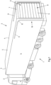
- FIG. 1 1 shows a commercial vehicle 1 pulled by a tractor Z, having a commercial vehicle body 2 in the form of a box body with a fixed front wall 3, side walls 4, and a fixed roof 5.
- the rear wall 6 of the commercial vehicle body 2 is formed by a rear wall frame 7 and a roller shutter 8, which is partially received in the rear wall frame 7.
- the roller shutter 8 comprises a wall element 9, which can be adjusted upwards and back down again along a rail system 10 on both sides of the roller shutter 8. In the upper, open position of the wall element 9, the wall element 9 releases the rear wall frame 7, at least in part, for loading and/or unloading a cargo space of the commercial vehicle body 2.
- the wall element 9 is then arranged at least substantially below the roof 5.
- the rail elements 11 of the rail system 10 comprise arches 12 in the connecting area of the roof 5 and the rear wall frame 7. Outside of these arches 12, the rail elements 11 of the rail system 10 of the illustrated and, in this respect, preferred commercial vehicle body 2 extend at least substantially in a straight line.
- the wall element 9 closes the rear wall frame 7. In this position, the wall element 9 is at least in the Essentially aligned parallel to the rear wall frame 7 and the wall element 9 can be locked at the lower edge of the rear wall frame 7.
- FIG. 2 A detail of the commercial vehicle 1 is shown in the area of the rear wall frame 7 with the upper end of the roller shutter 8 as seen from the loading space 13.
- the rollers 14 are held on roller holders 15 that are connected to panels 16, 17 of the wall element 9.
- the rollers 14 roll up and down along the rail system 10 or the rail elements 11, just as the associated panels 16, 17 are adjusted up and down again.
- the panels 16, 17 are connected to one another in a form-fitting manner and can be pivoted relative to one another, in particular rotatable about a longitudinal axis, so that the panels 16, 17 remain securely connected to one another during the adjustment of the wall element 9.
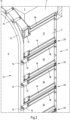
- FIG. 3 Three interconnected panels 16, 17 are shown.
- the connection is provided by upper connecting profiles 18 and lower connecting profiles 19 of the panels 16, 17, which interlock in a form-fitting manner.
- the upper connecting profiles 18 and the lower connecting profiles 19 are each designed to be similar and correspond to one another in such a way that the adjacent connecting profiles 18, 19 of the adjacent panels 16, 17 can be connected.
- the connectability of the panels 16, 17 to one another is not limited to this. Rather, each of the upper connecting profiles 18, 19 of any panel 16, 17 of the wall element 9 can be connected in a form-fitting manner to a lower connecting profile 19 of any other panel 16, 17 of the wall element 9.
- the upper connecting profiles 18 of the panels 16, 17 and also the lower connecting profiles 19 of the panels 16, 17 are identical to one another.
- FIG. 4A Two different panels 16, 17 of the wall element 9 are shown.
- the wall element 9 shown, and in this respect preferred, has the slightly narrower panel 17 shown on the right only once.
- the other panels 16 of the wall element 9 all correspond identically to the wider panel 16 shown on the left.
- the width of the shown, and in this respect preferred, panels 16, 17 is measured from the upper edge of the upper connecting profile 18 to the lower edge of the lower connecting profile 19.
- they have three hollow profile sections 20 between the connecting profiles 18, 19, which are provided one after the other and adjacent to one another.
- a T-slot 21 is provided, each assigned to the upper edge and the lower edge of the panels 16, 17.
- T-slots 21 can be inserted into these T-slots, to which, for example, roller holders 15 for holding the rollers 14 guided in the rail system 10 can be mounted, in particular screwed.
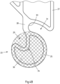
- the upper connecting profiles 18 are designed in the form of groove profiles 22, while the lower connecting profiles 19 are designed in the form of tongue profiles 23.
- the lower connecting profiles to be the groove profiles and the upper connecting profiles to be the tongue profiles.
- the groove profiles 22 have an at least substantially three-quarter-circular groove region 24, in which an at least substantially three-quarter-circular tongue region 25 of a tongue profile 23 can be received.
- the at least substantially three-quarter-circular groove region 24 extends from opposite sides to an opening 26 in the groove profile 22, via which the tongue profile 23 can be angled into the groove profile 22.
- the groove profile 22 is provided in the region of the groove region 24 on the associated panel base body 27.
- the tongue profile 23 is connected to the panel base body 27 via a web 28.
- the spring profile 23 is designed as a closed partial profile and is configured in the sense of a hollow profile. Between the three-quarter-circular spring area 25 and the web 28, a receptacle is provided in the illustrated and thus preferred spring profile 23. 29 is provided, which is formed by a recess in the contour of the spring profile 23 towards the inside.
- an imaginary spring circle 30 is shown, which is defined in a cross-section of the spring profile 23 by the at least substantially three-quarter-circular spring region 25.
- the circumference of the spring circle 30 and the circumference of the at least substantially three-quarter-circular spring region 25 correspond to one another at least substantially in sections.
- the receptacle 29 is arranged within the spring circle 30.
- the web 28 ensures a distance between the spring profile 23 and the panel base body 27, so that an outwardly open free space 31 remains between the spring profile 23 and the panel base body 27, which extends inwards as far as the web 27.
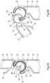
- FIG. 5A-B The connection 32 between an upper connecting profile 18 and a lower connecting profile 19 of two adjacent panels 16 is shown in detail, once when connected by angling into each other and once in the connected state.
- angling the tongue profile 23 and groove profile 22 into each other according to Fig. 5A An edge of the groove profile 22 is inserted into the receptacle 29 of the tongue profile 23 before the two panels 16 to be connected are pivoted against each other. In doing so, the tongue profile 23 enters the groove profile 22, whereby the tongue profile 23 slides further into the groove profile 22, which is illustrated by the arrow. In the manner described, a positive connection 32 is formed between the two adjacent panels 16.
- connection 32 is in the Fig. 5B
- the receptacle 29 is arranged at least substantially in the region of the opening 26 of the groove profile 22, and the three-quarter-circular groove region 24 and the three-quarter-circular tongue region 25 lie at least substantially completely against one another.
- the pivot axis 34 preferably extends through the center of the spring circle 30.
- FIG. 6 The upper section of the wall element 9 is shown, wherein the upper connecting profile 18 of the uppermost panel 17 is connected to a sealing strip 35, which is supported from the inside on an upper edge of the rear wall frame 7 when the wall element 9 is in the lower, closed position.
- a metal strip 36 extending in the longitudinal direction of the panel 17 is provided in the sealing strip 35, through which metal strip the sealing strip 35 is screwed to the groove area 52 of the upper connecting profile 18 via screws 37.
- the sealing strip 35 engages the upper edge of the groove area 25 in a form-fitting manner.
- FIG. 7 the lower section of the wall element 9 is shown with the lower connecting profile 19 of the lowest panel 16 of the wall element 9.
- a sealing strip 39 having a longitudinally extending metal strip 38 is provided on the tongue area 25 of the lower connecting profile.
- the sealing strip 39 is screwed to the metal strip 38 at the lower end of the tongue area 25 using screws 40.
- the sealing strip 39 engages in a form-fitting manner around the tongue area 25 of the lower connecting profile 19.
- a free end of the sealing strip 39 is folded back with respect to the free end and thus accommodated in a receptacle 41 for an end area of the groove area 24, resting against the connecting profile 19.
- This receptacle 41 fulfills different functions for different panels 16, 17.
- the sealing strip 39 therefore wedges when pull-out forces act on the sealing strip 39.
- the sealing strip 39 therefore remains reliably held on the lower connecting profile 16.
- the sealing strip 39 is also supported at opposite ends on a lower edge of the rear wall frame 7 or the loading floor 42 of the commercial vehicle body 2.
Landscapes
- Engineering & Computer Science (AREA)
- Mechanical Engineering (AREA)
- Body Structure For Vehicles (AREA)
Priority Applications (1)
| Application Number | Priority Date | Filing Date | Title |
|---|---|---|---|
| EP23217178.5A EP4570546A1 (fr) | 2023-12-15 | 2023-12-15 | Structure de véhicule utilitaire et véhicule utilitaire doté d'une porte roulante |
Applications Claiming Priority (1)
| Application Number | Priority Date | Filing Date | Title |
|---|---|---|---|
| EP23217178.5A EP4570546A1 (fr) | 2023-12-15 | 2023-12-15 | Structure de véhicule utilitaire et véhicule utilitaire doté d'une porte roulante |
Publications (1)
| Publication Number | Publication Date |
|---|---|
| EP4570546A1 true EP4570546A1 (fr) | 2025-06-18 |
Family
ID=89223542
Family Applications (1)
| Application Number | Title | Priority Date | Filing Date |
|---|---|---|---|
| EP23217178.5A Pending EP4570546A1 (fr) | 2023-12-15 | 2023-12-15 | Structure de véhicule utilitaire et véhicule utilitaire doté d'une porte roulante |
Country Status (1)
| Country | Link |
|---|---|
| EP (1) | EP4570546A1 (fr) |
Citations (2)
| Publication number | Priority date | Publication date | Assignee | Title |
|---|---|---|---|---|
| US4532973A (en) * | 1983-06-15 | 1985-08-06 | Defalco Ralph | Overhead door construction |
| WO2003076752A1 (fr) * | 2002-03-08 | 2003-09-18 | Proplas Ltd. | Construction de porte a panneaux plastiques |
-
2023
- 2023-12-15 EP EP23217178.5A patent/EP4570546A1/fr active Pending
Patent Citations (2)
| Publication number | Priority date | Publication date | Assignee | Title |
|---|---|---|---|---|
| US4532973A (en) * | 1983-06-15 | 1985-08-06 | Defalco Ralph | Overhead door construction |
| WO2003076752A1 (fr) * | 2002-03-08 | 2003-09-18 | Proplas Ltd. | Construction de porte a panneaux plastiques |
Similar Documents
| Publication | Publication Date | Title |
|---|---|---|
| DE19846823C2 (de) | Laderaumabdeckung für einen Laderaum eines Kraftfahrzeuges | |
| DE3236034C2 (de) | Schwenkbares Fahrzeugdach | |
| EP3293027B1 (fr) | Toit d'une structure bachee comprenant une structure de longeron | |
| EP2236711A2 (fr) | Fermeture de hayon d'une structure de chargement de véhicule utilitaire | |
| EP3705330B1 (fr) | Structure de bâche pourvue de dispositif d'arrêt de montant coulissant | |
| DE202012104195U1 (de) | Nutzfahrzeugaufbau mit mindestens einer Seitenplane | |
| EP1002694B1 (fr) | Véhicule réfrigéré | |
| DE29801555U1 (de) | Aufbau für ein Transportfahrzeug | |
| EP1955932A2 (fr) | Mécanisme de fermeture pour une structure de véhicule | |
| EP2703214B1 (fr) | Paroi de séparation pour un véhicule utilitaire et véhicule utilitaire équipé de cette paroi de séparation | |
| EP0445424B1 (fr) | Carrosserie en forme de caisse pour véhicules | |
| EP4570543A1 (fr) | Structure de véhicule utilitaire dotée d'une porte roulante et véhicule utilitaire | |
| EP4570545A1 (fr) | Structure de véhicule utilitaire avec porte roulante | |
| EP4570544A1 (fr) | Structure de véhicule utilitaire avec porte roulante | |
| EP3695996B1 (fr) | Caisse à verrouillage en court-circuit | |
| EP4265451B1 (fr) | Structure de bâche d'un véhicule utilitaire à recouvrement coulissant | |
| DE102008015757B3 (de) | Variabler Wechselkoffer | |
| EP0698545A1 (fr) | Chariot à deux étages | |
| DE1964814C3 (de) | Schiebewand für Fahrzeuge, insbesondere Eisenbahngüterwagen | |
| EP3964429B1 (fr) | Structure de bâche et véhicule utilitaire pourvu de bâche à panneaux | |
| WO2002022386A1 (fr) | Vehicule comportant une carrosserie | |
| EP3733318B1 (fr) | Procédé de fabrication d'un profilé extrudé formé et structure de véhicule utilitaire dotée d'un tel profilé | |
| DE2611141A1 (de) | Aufbau fuer lastfahrzeuge | |
| EP4275933A1 (fr) | Construction d'un véhicule utilitaire pourvu de portes arrière | |
| DE102018122542A1 (de) | Thermisch isolierte Kippbrücke |
Legal Events
| Date | Code | Title | Description |
|---|---|---|---|
| PUAI | Public reference made under article 153(3) epc to a published international application that has entered the european phase |
Free format text: ORIGINAL CODE: 0009012 |
|
| STAA | Information on the status of an ep patent application or granted ep patent |
Free format text: STATUS: THE APPLICATION HAS BEEN PUBLISHED |
|
| AK | Designated contracting states |
Kind code of ref document: A1 Designated state(s): AL AT BE BG CH CY CZ DE DK EE ES FI FR GB GR HR HU IE IS IT LI LT LU LV MC ME MK MT NL NO PL PT RO RS SE SI SK SM TR |
|
| STAA | Information on the status of an ep patent application or granted ep patent |
Free format text: STATUS: REQUEST FOR EXAMINATION WAS MADE |
|
| 17P | Request for examination filed |
Effective date: 20251213 |