EP4570643A1 - Antriebsanordnung für eine schiffsantriebseinheit mit zwei propellern - Google Patents
Antriebsanordnung für eine schiffsantriebseinheit mit zwei propellern Download PDFInfo
- Publication number
- EP4570643A1 EP4570643A1 EP23215541.6A EP23215541A EP4570643A1 EP 4570643 A1 EP4570643 A1 EP 4570643A1 EP 23215541 A EP23215541 A EP 23215541A EP 4570643 A1 EP4570643 A1 EP 4570643A1
- Authority
- EP
- European Patent Office
- Prior art keywords
- drive shaft
- outer drive
- primary
- bearings
- liquid lubricant
- Prior art date
- Legal status (The legal status is an assumption and is not a legal conclusion. Google has not performed a legal analysis and makes no representation as to the accuracy of the status listed.)
- Pending
Links
Images

Classifications
-
- B—PERFORMING OPERATIONS; TRANSPORTING
- B63—SHIPS OR OTHER WATERBORNE VESSELS; RELATED EQUIPMENT
- B63H—MARINE PROPULSION OR STEERING
- B63H21/00—Use of propulsion power plant or units on vessels
- B63H21/38—Apparatus or methods specially adapted for use on marine vessels, for handling power plant or unit liquids, e.g. lubricants, coolants, fuels or the like
- B63H21/386—Apparatus or methods specially adapted for use on marine vessels, for handling power plant or unit liquids, e.g. lubricants, coolants, fuels or the like for handling lubrication liquids
-
- B—PERFORMING OPERATIONS; TRANSPORTING
- B63—SHIPS OR OTHER WATERBORNE VESSELS; RELATED EQUIPMENT
- B63H—MARINE PROPULSION OR STEERING
- B63H20/00—Outboard propulsion units, e.g. outboard motors or Z-drives; Arrangements thereof on vessels
- B63H20/001—Arrangements, apparatus and methods for handling fluids used in outboard drives
- B63H20/002—Arrangements, apparatus and methods for handling fluids used in outboard drives for handling lubrication liquids
-
- B—PERFORMING OPERATIONS; TRANSPORTING
- B63—SHIPS OR OTHER WATERBORNE VESSELS; RELATED EQUIPMENT
- B63H—MARINE PROPULSION OR STEERING
- B63H20/00—Outboard propulsion units, e.g. outboard motors or Z-drives; Arrangements thereof on vessels
- B63H20/14—Transmission between propulsion power unit and propulsion element
-
- B—PERFORMING OPERATIONS; TRANSPORTING
- B63—SHIPS OR OTHER WATERBORNE VESSELS; RELATED EQUIPMENT
- B63H—MARINE PROPULSION OR STEERING
- B63H20/00—Outboard propulsion units, e.g. outboard motors or Z-drives; Arrangements thereof on vessels
- B63H2020/005—Arrangements of two or more propellers, or the like on single outboard propulsion units
- B63H2020/006—Arrangements of two or more propellers, or the like on single outboard propulsion units of coaxial type, e.g. of counter-rotative type
-
- B—PERFORMING OPERATIONS; TRANSPORTING
- B63—SHIPS OR OTHER WATERBORNE VESSELS; RELATED EQUIPMENT
- B63H—MARINE PROPULSION OR STEERING
- B63H23/00—Transmitting power from propulsion power plant to propulsive elements
- B63H23/32—Other parts
- B63H23/321—Bearings or seals specially adapted for propeller shafts
- B63H2023/323—Bearings for coaxial propeller shafts, e.g. for driving propellers of the counter-rotative type
-
- B—PERFORMING OPERATIONS; TRANSPORTING
- B63—SHIPS OR OTHER WATERBORNE VESSELS; RELATED EQUIPMENT
- B63H—MARINE PROPULSION OR STEERING
- B63H23/00—Transmitting power from propulsion power plant to propulsive elements
- B63H23/32—Other parts
- B63H23/321—Bearings or seals specially adapted for propeller shafts
- B63H2023/327—Sealings specially adapted for propeller shafts or stern tubes
-
- B—PERFORMING OPERATIONS; TRANSPORTING
- B63—SHIPS OR OTHER WATERBORNE VESSELS; RELATED EQUIPMENT
- B63H—MARINE PROPULSION OR STEERING
- B63H23/00—Transmitting power from propulsion power plant to propulsive elements
- B63H23/32—Other parts
- B63H23/321—Bearings or seals specially adapted for propeller shafts
Definitions
- the present disclosure relates to a drive assembly for a marine dual-propeller drive unit. Specifically, the present disclosure relates to a design of a lubrication system integrated in such drive assemblies.
- Marine dual-propeller drive units typically comprise two co-axial drive shafts each configured to carry a respective propeller. In use the propellers are typically counter rotating.
- the inner drive shaft is supported in the outer drive shaft, typically using bearings.
- a space between the outer drive shaft and the inner drive shaft is typically filled with liquid lubricant for lubrication of the bearings.
- a general goal of the present disclosure is to reduce friction in the marine dual-propeller drive unit, thereby reducing power consumption.
- the goal is achieved by a drive assembly for a marine dual-propeller drive unit.
- the drive assembly comprises:
- the outer drive shaft comprises a through central opening extending along a rotational axis of the outer drive shaft.
- the inner drive shaft extends co-axially with the outer drive shaft, through the central opening of the outer drive shaft.
- a plurality of primary bearings are mounted in the central opening for rotationally supporting the inner drive shaft in the outer drive shaft such that the inner drive shaft and the outer drive shaft are rotatable relatively each other about the rotational axis.
- a plurality of secondary bearings are mounted around the outer drive shaft for rotatably supporting the outer drive shaft in the housing such that the outer drive shaft is rotatable relatively the housing about the rotational axis.
- the lubrication system comprises a liquid lubricant pump, and a primary fluid channel comprising a primary inlet fluidly connected to the liquid lubricant pump 12 for receiving pressurized liquid lubricant, and at least one primary outlet emanating in the central opening of the outer drive shaft.
- the outer drive shaft comprises at least one secondary fluid channel extending from a secondary inlet facing the central opening to a secondary outlet facing an outer space between the housing and a radial outside of the outer drive shaft.
- the outer drive shaft is provided with at least one protrusion protruding radially inwards from an inner surface of the outer drive shaft.
- the secondary inlet of the secondary fluid channel is provided in said at least one protrusion at a first radial level offset radially inwards from the inner surface of the outer drive shaft such that liquid lubricant at said first radial level is able to lubricate at least some of the primary bearings.
- liquid lubricant such as a suitable oil
- liquid lubricant is forced by the pump into the central opening of the outer drive shaft through the primary fluid channel.
- the liquid lubricant is forced radially outwards by centrifugal force thereby spreading the liquid lubricant in the central opening space along the length of the outer drive shaft.
- the radial thickness of the layer of liquid lubricant formed inside the central opening increases and eventually the thickness of the layer of liquid lubricant will be enough to provide proper lubrication to the primary bearings.
- liquid lubricant will also be forced though one or more primary bearings.
- any tapered roller bearings will, depending on their orientation, provide an additional force moving liquid lubricant through the tapered bearing.
- the pressure of the liquid lubricant may also be used to force liquid lubricant through the secondary bearings supporting the outer drive shaft in the housing.
- the secondary fluid channel enables liquid lubricant to escape the central opening such that the space between the outer drive shaft and the inner drive shaft is not filled with liquid lubricant, thereby enabling the inner shaft to rotate surrounded by gas rather than liquid, such that friction between the inner drive shaft and the surrounding fluid is mitigated.
- the provision of the at least one protrusion offset radially inwards from the inner surface of the outer drive shaft establishes a minimum thickness of the layer of liquid lubricant, thus ensuring proper lubrication of primary bearings.
- the housing may be provided with a return channel fluidly connecting a lower portion of the outer space to a sump.
- the sump may be vented to atmospheric pressure and said liquid lubricant pump fluidly connected to the sump to pump liquid lubricant from the sump.
- liquid lubricant As liquid lubricant passes through the secondary fluid channel, the liquid lubricant will eventually reach the housing and flow to the sump by the force of gravity.
- the pump picks up liquid lubricant from the sump and forces it back into the first fluid channel. Accordingly, liquid lubricant is circulated in the drive assembly without filling up the central opening of the outer drive shaft.
- the sump is fluidly connected to ambient air at atmospheric pressure.
- the protrusion comprises a ridge extending circumferentially about the rotational axis.
- the circumferential extension of the ridge promotes improved spread of liquid lubricant as liquid lubricant fills up on the side of the ridge from which liquid lubricant is supplied from the pump and flows over the ridge to the other axial side of the ridge.
- said protrusion is formed by an insert mounted to the outer drive shaft.
- the insert allows the inner drive shaft to be inserted into the central opening of the outer drive shaft before the insert is mounted. Hence, the protrusion will not obstruct mounting of the inner drive shaft and the primary bearings.
- the outer drive shaft comprises a plurality of said secondary fluid channels.
- the provision of a plurality of secondary fluid channels promotes an even distribution of the thickness of the layer of liquid lubricant inside the outer drive shaft and reduces the risk of failure due to clogging of the secondary fluid channel. Also, improved balancing of the outer drive shaft is enabled since the positions of the secondary fluid channels may be varied at production of the outer drive shaft. Further, the cross-sectional size of each secondary fluid channel may be decreased without reducing the total cross-sectional size of the secondary fluid channels, hence promoting a more even spread of stress through the material of the outer drive shaft.
- the plurality of secondary fluid channels are circumferentially distributed about the rotational axis such that the outer drive shaft is balanced about the rotational axis.
- the primary fluid channel extends through the housing to a confined space between the outer drive shaft and the housing, and through one or more fluid channels in the outer drive shaft from the confined space to said one or more primary outlets.
- liquid lubricant As liquid lubricant is pumped into the confined space, the space is filled with liquid lubricant. As more liquid lubricant is pumped into the confined space, liquid lubricant leaves the confined space via the one or more fluid channels to the one or more primary outlets.
- the confined space provides a fluid path from the pump to the primary outlets independently of the relative rotation between the outer drive shaft and the housing, hence enabling continuous lubrication also when the outer drive shaft is rotating relatively the housing.
- the primary bearings comprise two tapered roller bearings provided at the inner end portion of the inner drive shaft.
- the tapered roller bearings are spaced-apart and oriented to withstand axial force in opposite axial directions.
- the primary fluid channel comprises a primary outlet emanating between the tapered roller bearings of the primary bearings.
- the tapered roller bearings rotatably support the inner drive shaft and co-operate to withstand axial loading of the inner drive shaft caused by force from a propeller mounted on the inner drive shaft.
- the provision of a primary outlet between the tapered roller bearings enabled liquid lubricant to be forced through the tapered roller bearings, thus ensuring proper lubrication also for the tapered roller bearing closest to inner end portion of the inner drive shaft.
- some liquid lubricant may move directly from the central opening to the sump through one of the tapered roller bearings, whilst some liquid lubricant will move through the other tapered roller bearing and subsequently form the layer of liquid lubricant and eventually exit through the secondary fluid channel(s).
- the secondary bearings comprise two tapered roller bearings provided at the inner end portion of the outer drive shaft, said tapered roller bearings being spaced-apart and oriented to withstand axial force in opposite axial directions, and said confined space being provided between the tapered roller bearings of the secondary bearings.
- the tapered roller bearings rotatably support the outer drive shaft and co-operate to withstand axial loading of the outer drive shaft caused by force from a propeller mounted on the outer drive shaft.
- the provision of a primary outlet between the tapered roller bearings enabled liquid lubricant to be forced through the tapered roller bearings, thus ensuring proper lubrication also for the tapered roller bearing closest to inner end portion of the outer drive shaft.
- some liquid lubricant will move directly from the confined space to the sump through the respective tapered roller bearings, whilst some liquid lubricant will move to the one or more primary outlets.
- the primary bearings further comprise at least one bearing provided at the outer end portion of the inner drive shaft.
- the bearing provided at the outer end portion of the inner drive shaft cooperates with the other secondary bearings to withstand radial forces and associated momentum on the inner drive shaft.
- the primary bearing provided at the outer end portion of the inner drive shaft is a needle bearing.
- a first seal is provided between the inner drive shaft and the outer drive shaft at the outer end portion, and a second seal is provided between the outer drive shaft and the housing at the outer end portion of the outer drive shaft.
- the seals keep liquid lubricant inside the housing and thus lowers consumption of liquid lubricant thus enabling use of a lower-capacity pump with lower energy consumption.
- a propeller drive unit comprising the drive shaft assembly described above, a motor and a planetary gear.
- the planetary gear comprises a ring gear, a planetary carrier and a sun gear.
- the ring gear may be connected to the outer drive shaft, and the planetary carrier may be connected to the inner drive shaft or integrated with the inner drive shaft.
- the sun gear is operatively connected to the motor.
- the planetary gear provides a simple and robust means of rotating the outer drive shaft and the inner drive shaft in different rotational directions with respect to the rotational axis.
- a marine vessel comprising the above-described propeller drive unit.
- the marine vessel may for example be a boat or a ship.
- a problem to be solved by the present disclosure is how to reduce friction in a marine dual-propeller drive unit, thereby reducing power consumption.
- This problem is solved by a drive assembly 1 for a marine dual-propeller drive unit.
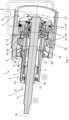
- a first embodiment of the drive assembly 1 is shown in fig. 1 .
- the drive assembly 1 comprises: a housing 2, an outer drive shaft assembly comprising an outer drive shaft 3 comprising an outer end portion 4 for holding a first propeller (not shown) and an axially opposite inner end portion 5 for connection to a gear ( fig. 2 ) or a motor, an inner drive shaft assembly comprising an inner drive shaft 6 comprising and outer end portion 7 for holding a second propeller (not shown) and an axially opposite inner end portion 8 for connection to a gear ( fig. 2 ) or a motor, and a lubrication system.
- the outer drive shaft 3 comprises a through central opening 9 extending along a rotational axis 10 of the outer drive shaft 3.
- the inner drive shaft 6 extends co-axially with the outer drive shaft 3, through the central opening 9 of the outer drive shaft 3.
- a plurality of primary bearings 11 are mounted in the central opening 9 for rotationally supporting the inner drive shaft 6 in the outer drive shaft 3 such that the inner drive shaft 6 and the outer drive shaft 3 are rotatable relatively each other about the rotational axis 10.
- the respective end portions for receiving a propeller are indicated by the propeller symbols in Fig. 1 .
- the number of primary bearings 11 may be higher or lower and the type of bearings of the primary bearings 11 may differ from the ones of this embodiment.
- a plurality of secondary bearings 22 are mounted around the outer drive shaft 3 for rotatably supporting the outer drive shaft 3 in the housing 2 such that the outer drive shaft 3 is rotatable relatively the housing 2 about the rotational axis 10.
- the number of secondary bearings 22 may be higher or lower and the type of bearings of the secondary bearings 22 may differ from the ones of this embodiment.
- the lubrication system comprises a liquid lubricant pump 12, and a primary fluid channel 13 comprising a primary inlet 14 fluidly connected to the liquid lubricant pump 12 for receiving pressurized liquid lubricant, and at least one primary outlet 15 emanating in the central opening 9 of the outer drive shaft 3.
- the outer drive shaft 3 comprises at least one secondary fluid channel 16 extending from a secondary inlet 17 facing the central opening 9 to a secondary outlet 18 facing an outer space 19 between the housing 2 and a radial outside of the outer drive shaft 3.
- the outer drive shaft 3 is provided with at least one protrusion 20 protruding radially inwards from an inner surface of the outer drive shaft 3.
- the secondary inlet 17 of the secondary fluid channel 16 is provided in said at least one protrusion 20 at a first radial level 21 offset radially inwards from the inner surface of the outer drive shaft 3 such that liquid lubricant at said first radial level 21 is able to lubricate at least some of the primary bearings 11.
- liquid lubricant such as a suitable oil
- the pump 12 In use, liquid lubricant, such as a suitable oil, is forced by the pump 12 into the central opening 9 of the outer drive shaft 3 through the primary fluid channel 13. Inside the central opening 9, the liquid lubricant is forced radially outwards by centrifugal force thereby spreading the liquid lubricant in the central opening 9 along the length of the outer drive shaft 3. As more liquid lubricant is pumped into the central opening 9, the radial thickness D1 of the layer of liquid lubricant formed inside the central opening 9 increases and eventually the thickness of the layer of liquid lubricant will be enough to provide proper lubrication to the primary bearings 11.
- liquid lubricant will also be forced though one or more primary bearings 11.
- any tapered roller bearings 23, 24 will, depending on its orientation, provide an additional force moving liquid lubricant through the tapered roller bearing 23, 24.
- the pressure of the liquid lubricant may also be used to force liquid lubricant through the secondary bearings 22 supporting the outer drive shaft 3 in the housing 2.
- the secondary fluid channel 16 enables liquid lubricant to escape the central opening 9 such that the space between the outer drive shaft 3 and the inner drive shaft 6 is not filled with liquid lubricant, thereby enabling the inner shaft to rotate surrounded by gas rather than liquid, such that friction between the inner drive shaft 6 and the surrounding fluid is mitigated.
- the housing 2 is provided with a return channel 26 fluidly connecting a lower portion of the outer space to a sump 27.
- the sump (27) may be vented to atmospheric pressure and said liquid lubricant pump 12 fluidly connected to the sump 27 to pump liquid lubricant from the sump 27.
- the position, size and extent of the return channel 26 is preferably such that liquid lubricant is able to flow through the return channel 26 by the force of gravity. In other embodiments, the return channel 26 may have any other suitable position, size and extent.
- liquid lubricant As liquid lubricant passes through the secondary fluid channel 16, the liquid lubricant will eventually reach the housing 2 and flow to the sump 27 by the force of gravity.
- the pump 12 picks up liquid lubricant from the sump 27 and forces it back into the first fluid channel. Accordingly, liquid lubricant is circulated in the drive assembly 1 without filling up the central opening 9 of the outer drive shaft 3.
- the sump 27 is fluidly connected to ambient air at atmospheric pressure but may in other embodiments be isolated from ambient air.
- the at least one protrusion 20 protruding radially inwards from an inner surface of the outer drive shaft 3 comprises a ridge 28 extending circumferentially about the rotational axis 10.
- the protrusion 20 may have any other suitable shape, for example without a ridge 28.
- the protrusion 20 of the embodiment illustrated in Fig. 1 may be produced in a cost-effective manner by turning.
- the circumferential extension of the ridge 28 promotes improved spread of liquid lubricant as liquid lubricant fills up on the side of the ridge 28 from which liquid lubricant is supplied from the pump 12 and flows over the ridge 28 to the other axial side of the ridge 28.
- the insert allows the inner drive shaft 6 to be inserted into the central opening 9 of the outer drive shaft 3 before the insert is mounted. Hence, the protrusion 20 will not obstruct mounting of the inner drive shaft 6 and the primary bearings 11.
- the outer drive shaft 3 comprises two of said secondary fluid channels 16. In other embodiments, the outer drive shaft 3 may alternatively comprise only one secondary fluid channel 16, or more than two secondary fluid channels 16.
- the provision of a plurality of secondary fluid channels 16 promotes an even distribution of the thickness of the layer of liquid lubricant inside the outer drive shaft 3 and reduces the risk of failure due to clogging of the secondary fluid channel 16. Also, improved balancing of the outer drive shaft 3 is enabled since the positions of the secondary fluid channels 16 may be varied at production of the outer drive shaft 3. Further, the cross-sectional size of each secondary fluid channel 16 may be decreased without reducing the total cross-sectional size of the secondary fluid channels 16, hence promoting a more even spread of stress through the material of the outer drive shaft 3.
- the plurality of secondary fluid channels 16 are circumferentially distributed about the rotational axis 10 such that the outer drive shaft 3 is balanced about the rotational axis 10.
- the plurality of secondary fluid channels 16 may alternatively be otherwise distributed and positioned in other positions than the ones shown in Fig. 1 .
- a plurality of secondary fluid channels 16 may have different axial positions with respect to the rotational axis 10.
- the primary fluid channel 13 extends through the housing 2 to a confined space 25 between the outer drive shaft 3 and the housing 2, and through one or more fluid channels in the outer drive shaft 3 from the confined space 25 to said one or more primary outlets 15.
- the fluid channel through the outer drive shaft 3 may be achieved using any suitable production method, but in the present embodiment it is produced by drilling a hole from the inner end portion 5 of the outer drive shaft 3 substantially parallel to the rotational axis 10 and by radially drilling two other holes such that a first radially drilled hole connects to the confined space 25, and such that a second radially drilled hole forms one of said at least one primary outlets 15 and fluidly connects to the axially drilled hole.
- an outer opening of the axially drilled hole is subsequently plugged, or otherwise closed, to prevent liquid lubricant from exiting the primary fluid channel 13 through an inner end of the outer drive shaft 3.
- the confined space 25 may be achieved in any suitable way, such as by providing a radial spacing between the outer drive shaft 3 and the housing 2, and axially surrounding the confined space 25 using bearings and/or ridges extending from the housing 2 or extending from the outer drive shaft 3.
- two bearings 11, 23 axially confined the confined space 25 but in other embodiments, a close fit between the housing 2 and an outer surface of the outer drive shaft 3 may sufficiently prevent/limit fluid leak from the confined space 25 radially outside the outer drive shaft 3. Further, one or more seals may be provided between the housing 2 and the outer drive shaft 3 to axially confine the confined space 25.
- liquid lubricant As liquid lubricant is pumped into the confined space 25, the space is filled with liquid lubricant. As more liquid lubricant is pumped into the confined space 25, liquid lubricant leaves the confined space 25 via the one or more fluid channels to the one or more primary outlets 15.
- the confined space 25 provides a fluid path from the pump 12 to the primary outlets 15 independently of the relative rotation between the outer drive shaft 3 and the housing 2, hence enabling continuous lubrication also when the outer drive shaft 3 is rotating relatively the housing 2.
- the primary bearings 11 in this embodiment comprises two tapered roller bearings 23 provided at the inner end portion 8 of the inner drive shaft 6.
- the tapered roller bearings 23 are spaced-apart and oriented to withstand axial force in opposite axial directions.
- the primary fluid channel 13 comprises a primary outlet 15 emanating between the tapered roller bearings 23 of the primary bearings 11.
- the primary outlets 15 may be provided at other positions, not necessarily between the tapered roller bearings 23, as long as the liquid lubricant is able to move through, or past, the bearings to reach and sufficiently lubricate all bearings.
- an axially extending groove may be provided on an inside surface of the outer drive shaft 3 to enable increased flow of liquid lubricant past one or more primary bearings 11.
- the tapered roller bearings 23 rotatably support the inner drive shaft 6 and co-operate to withstand axial loading of the inner drive shaft 6 caused by force from a propeller mounted on the inner drive shaft 6.
- the provision of a primary outlet 15 between the tapered roller bearings 23 enabled liquid lubricant to be forced through the tapered roller bearings 23, thus ensuring proper lubrication also for the tapered roller bearing closest to inner end portion 8 of the inner drive shaft 6.
- some liquid lubricant may move directly from the central opening 9 to the sump 27 through one of the tapered roller bearings 23, whilst some liquid lubricant will move through the other tapered roller bearing and subsequently form the layer of liquid lubricant and eventually exit through the secondary fluid channels 16.
- the secondary bearings 22 comprise two tapered roller bearings 24 provided at the inner end portion 5 of the outer drive shaft 3, said tapered roller bearings 24 being spaced-apart and oriented to withstand axial force in opposite axial directions, and said confined space 25 being provided between the tapered roller bearings 24 of the secondary bearings 22.
- other types of bearings may alternatively be provided adjacent the confined space 25, or no primary bearings 11 may be provided adjacent the confined space 25, as discussed above.
- the tapered roller bearings 24 rotatably support the outer drive shaft 3 and co-operate to withstand axial loading of the outer drive shaft 3 caused by force from a propeller mounted on the outer drive shaft 3.
- the provision of a primary outlet 15 between the tapered roller bearings 24 enabled liquid lubricant to be forced through the tapered roller bearings 24, thus ensuring proper lubrication also for the tapered roller bearing closest to inner end portion 5 of the outer drive shaft 3.
- some liquid lubricant will move directly from the confined space 25 to the sump 27 through the respective tapered roller bearings 24, whilst some liquid lubricant will move to the one or more primary outlets 15.
- the primary bearings 11 further comprise at least one bearing provided at the outer end portion 7 of the inner drive shaft 6. In other embodiments, this bearing may alternatively be omitted or otherwise positioned, depending on the calculated stress and need of off-loading other primary bearings 11.
- the bearing provided at the outer end portion 7 of the inner drive shaft 6 cooperates with the other secondary bearings 22 to withstand radial forces and associated momentum on the inner drive shaft 6.
- the primary bearing 11 provided at the outer end portion 7 of the inner drive shaft 6 is a needle bearing but may in other embodiments alternatively be any other suitable type of bearing.
- a first seal 29 is provided between the inner drive shaft 6 and the outer drive shaft 3 at the outer end portion 7, and a second seal 30 is provided between the outer drive shaft 3 and the housing 2 at the outer end portion 4 of the outer drive shaft 3.
- the number of seals and positions of the seals may be suitably varied.
- the seals may be omitted although that would lead to increased use of liquid lubricant.
- the seals keep liquid lubricant inside the housing 2 and thus lowers consumption of liquid lubricant thus enabling use of a lower-capacity pump 12 with lower energy consumption.
- a propeller drive unit is provided (the propeller drive unit is not shown in Fig. 1 ).
- the propeller drive unit comprises the drive assembly 1 described above, a planetary gear and preferably a motor.
- the planetary gear comprises a ring gear 31, a planetary carrier 32 and a sun gear 33.
- the ring gear 31 may be connected to the outer drive shaft 3, and the planetary carrier 32 may be connected to the inner drive shaft 6 or integrated with the inner drive shaft 6.
- the sun gear 33 is operatively connected to, or connectable to, said motor.
- the planetary gear may be omitted and torque provided to the respective drive shaft in any other suitable way, such as from a respective motor.
- the motor may be a combustion engine or an electric motor, or a hybrid-electric motor.
- the planetary gear provides a simple and robust means of rotating the outer drive shaft 3 and the inner drive shaft 6 in different rotational directions with respect to the rotational axis 10.
- Relative terms such as “below” or “above” or “upper” or “lower” or “horizontal” or “vertical” may be used herein to describe a relationship of one element to another element as illustrated in the Figures. It will be understood that these terms and those discussed above are intended to encompass different orientations of the device in addition to the orientation depicted in the Figures. It will be understood that when an element is referred to as being “connected” or “coupled” to another element, it can be directly connected or coupled to the other element, or intervening elements may be present. In contrast, when an element is referred to as being “directly connected” or “directly coupled” to another element, there are no intervening elements present.
- Table of reference numerals 1 drive assembly 2 housing 3 outer drive shaft 4 outer end portion of outer drive shaft 5 inner end portion of outer drive shaft 6 inner drive shaft 7 outer end portion of inner drive shaft 8 inner end portion of inner drive shaft 9 through central opening 10 rotational axis 11 primary bearings 12 liquid lubricant pump 13 primary fluid channel 14 primary inlet (of primary fluid channel) 15 primary outlet (of primary fluid channel) 16 secondary fluid channel 17 secondary inlet of secondary fluid channel 18 secondary outlet of secondary fluid channel 19 outer space between housing and radial outside of outer drive shaft 20 protrusion inside outer drive shaft 21 first radial level 22 secondary bearings 23 tapered roller bearings of primary bearings 24 tapered roller bearings of secondary bearings 25 confined space 26 return channel 27 sump 28 ridge of protrusion 29 first seal 30 second seal 31 ring gear 32 planetary carrier 33 sun gear D1 radial thickness of layer of liquid lubricant
Landscapes
- Chemical & Material Sciences (AREA)
- Engineering & Computer Science (AREA)
- Combustion & Propulsion (AREA)
- Mechanical Engineering (AREA)
- Ocean & Marine Engineering (AREA)
- General Details Of Gearings (AREA)
Priority Applications (2)
| Application Number | Priority Date | Filing Date | Title |
|---|---|---|---|
| EP23215541.6A EP4570643A1 (de) | 2023-12-11 | 2023-12-11 | Antriebsanordnung für eine schiffsantriebseinheit mit zwei propellern |
| US18/972,269 US20250187710A1 (en) | 2023-12-11 | 2024-12-06 | Drive assembly for a marine dual-propeller drive unit |
Applications Claiming Priority (1)
| Application Number | Priority Date | Filing Date | Title |
|---|---|---|---|
| EP23215541.6A EP4570643A1 (de) | 2023-12-11 | 2023-12-11 | Antriebsanordnung für eine schiffsantriebseinheit mit zwei propellern |
Publications (1)
| Publication Number | Publication Date |
|---|---|
| EP4570643A1 true EP4570643A1 (de) | 2025-06-18 |
Family
ID=89168342
Family Applications (1)
| Application Number | Title | Priority Date | Filing Date |
|---|---|---|---|
| EP23215541.6A Pending EP4570643A1 (de) | 2023-12-11 | 2023-12-11 | Antriebsanordnung für eine schiffsantriebseinheit mit zwei propellern |
Country Status (2)
| Country | Link |
|---|---|
| US (1) | US20250187710A1 (de) |
| EP (1) | EP4570643A1 (de) |
Citations (2)
| Publication number | Priority date | Publication date | Assignee | Title |
|---|---|---|---|---|
| EP0221536A2 (de) * | 1985-11-08 | 1987-05-13 | Mitsubishi Jukogyo Kabushiki Kaisha | Stevenrohrlageranordnung für gegenläufige Propeller |
| JP3122198B2 (ja) * | 1991-10-15 | 2001-01-09 | 三菱重工業株式会社 | 二重反転式プロペラ装置における内軸用すべり軸受 |
-
2023
- 2023-12-11 EP EP23215541.6A patent/EP4570643A1/de active Pending
-
2024
- 2024-12-06 US US18/972,269 patent/US20250187710A1/en active Pending
Patent Citations (2)
| Publication number | Priority date | Publication date | Assignee | Title |
|---|---|---|---|---|
| EP0221536A2 (de) * | 1985-11-08 | 1987-05-13 | Mitsubishi Jukogyo Kabushiki Kaisha | Stevenrohrlageranordnung für gegenläufige Propeller |
| JP3122198B2 (ja) * | 1991-10-15 | 2001-01-09 | 三菱重工業株式会社 | 二重反転式プロペラ装置における内軸用すべり軸受 |
Also Published As
| Publication number | Publication date |
|---|---|
| US20250187710A1 (en) | 2025-06-12 |
Similar Documents
| Publication | Publication Date | Title |
|---|---|---|
| US8641569B2 (en) | Revolving apparatus for construction machine | |
| EP2748474B1 (de) | Achslager zur verwendung in einem epizyklischen getriebe und verfahren zur ermöglichung eines hydrodynamischen ölflusses in diesem achslager | |
| US9057431B2 (en) | Differential apparatus | |
| CN101842616B (zh) | 用于齿轮箱的供油组件 | |
| CN115681469B (zh) | 一种行星排润滑结构、混合动力电驱动总成及车辆 | |
| EP2472146A1 (de) | Planetenlagerstruktur | |
| CN115638239B (zh) | 一种行星排润滑结构、混合动力电驱动总成及车辆 | |
| CN113039379B (zh) | 风力发电设备的行星齿轮传动装置 | |
| KR20090104975A (ko) | 유성기어세트의 피니언기어 윤활장치 | |
| WO2010018630A1 (ja) | 風力発電装置 | |
| US9260980B2 (en) | Rotating fluid pumping system | |
| EP2662572A1 (de) | Abdichtungsanordnung für den Schmierstoff eines Kugellagers in einer Strömungsmaschine | |
| US4251186A (en) | Device to circulate a fluid in a hollow shaft | |
| US11066983B2 (en) | Lubricating device for bearing, and exhaust turbosupercharger | |
| JP2012202507A (ja) | 軸受装置およびポンプ装置 | |
| EP4570643A1 (de) | Antriebsanordnung für eine schiffsantriebseinheit mit zwei propellern | |
| KR100692153B1 (ko) | 자동변속기용 유성기어 세트 | |
| EP3765768B1 (de) | Getriebeanordnung mit üblichem getriebezug und vertikaler abtriebsachse | |
| JPS59106761A (ja) | 歯車装置の潤滑油導入装置 | |
| CN109826942A (zh) | 一种行星轮系轴承润滑结构 | |
| US12188553B1 (en) | Automotive drivetrain gearbox including differential housing including fluid flow holes | |
| EP3850247B1 (de) | Planetengetriebe und fahrzeug oder stationäre einheit mit solch einem planetengetriebe | |
| US6357552B1 (en) | Submersible pump assembly for downhole use | |
| EP4143437B1 (de) | Windturbine | |
| CN109707800B (zh) | 行星辊式变速器 |
Legal Events
| Date | Code | Title | Description |
|---|---|---|---|
| PUAI | Public reference made under article 153(3) epc to a published international application that has entered the european phase |
Free format text: ORIGINAL CODE: 0009012 |
|
| STAA | Information on the status of an ep patent application or granted ep patent |
Free format text: STATUS: REQUEST FOR EXAMINATION WAS MADE |
|
| 17P | Request for examination filed |
Effective date: 20250211 |
|
| AK | Designated contracting states |
Kind code of ref document: A1 Designated state(s): AL AT BE BG CH CY CZ DE DK EE ES FI FR GB GR HR HU IE IS IT LI LT LU LV MC ME MK MT NL NO PL PT RO RS SE SI SK SM TR |
|
| GRAP | Despatch of communication of intention to grant a patent |
Free format text: ORIGINAL CODE: EPIDOSNIGR1 |
|
| STAA | Information on the status of an ep patent application or granted ep patent |
Free format text: STATUS: GRANT OF PATENT IS INTENDED |
|
| RIC1 | Information provided on ipc code assigned before grant |
Ipc: B63H 21/38 20060101AFI20251121BHEP |
|
| INTG | Intention to grant announced |
Effective date: 20251204 |
|
| GRAS | Grant fee paid |
Free format text: ORIGINAL CODE: EPIDOSNIGR3 |
|
| GRAA | (expected) grant |
Free format text: ORIGINAL CODE: 0009210 |
|
| STAA | Information on the status of an ep patent application or granted ep patent |
Free format text: STATUS: THE PATENT HAS BEEN GRANTED |