EP4570648A1 - Flugzeug mit mindestens einer abnehmbaren druckenergieabsorptionsvorrichtung - Google Patents
Flugzeug mit mindestens einer abnehmbaren druckenergieabsorptionsvorrichtung Download PDFInfo
- Publication number
- EP4570648A1 EP4570648A1 EP24218929.8A EP24218929A EP4570648A1 EP 4570648 A1 EP4570648 A1 EP 4570648A1 EP 24218929 A EP24218929 A EP 24218929A EP 4570648 A1 EP4570648 A1 EP 4570648A1
- Authority
- EP
- European Patent Office
- Prior art keywords
- energy absorption
- compression energy
- compression
- absorption module
- aircraft
- Prior art date
- Legal status (The legal status is an assumption and is not a legal conclusion. Google has not performed a legal analysis and makes no representation as to the accuracy of the status listed.)
- Pending
Links
Images


Classifications
-
- B—PERFORMING OPERATIONS; TRANSPORTING
- B64—AIRCRAFT; AVIATION; COSMONAUTICS
- B64C—AEROPLANES; HELICOPTERS
- B64C1/00—Fuselages; Constructional features common to fuselages, wings, stabilising surfaces or the like
- B64C1/06—Frames; Stringers; Longerons ; Fuselage sections
- B64C1/061—Frames
- B64C1/062—Frames specially adapted to absorb crash loads
-
- B—PERFORMING OPERATIONS; TRANSPORTING
- B64—AIRCRAFT; AVIATION; COSMONAUTICS
- B64C—AEROPLANES; HELICOPTERS
- B64C1/00—Fuselages; Constructional features common to fuselages, wings, stabilising surfaces or the like
- B64C1/06—Frames; Stringers; Longerons ; Fuselage sections
- B64C1/12—Construction or attachment of skin panels
-
- B—PERFORMING OPERATIONS; TRANSPORTING
- B64—AIRCRAFT; AVIATION; COSMONAUTICS
- B64C—AEROPLANES; HELICOPTERS
- B64C27/00—Rotorcraft; Rotors peculiar thereto
-
- B—PERFORMING OPERATIONS; TRANSPORTING
- B64—AIRCRAFT; AVIATION; COSMONAUTICS
- B64C—AEROPLANES; HELICOPTERS
- B64C27/00—Rotorcraft; Rotors peculiar thereto
- B64C27/006—Safety devices
-
- B—PERFORMING OPERATIONS; TRANSPORTING
- B64—AIRCRAFT; AVIATION; COSMONAUTICS
- B64D—EQUIPMENT FOR FITTING IN OR TO AIRCRAFT; FLIGHT SUITS; PARACHUTES; ARRANGEMENT OR MOUNTING OF POWER PLANTS OR PROPULSION TRANSMISSIONS IN AIRCRAFT
- B64D37/00—Arrangements in connection with fuel supply for power plant
- B64D37/02—Tanks
- B64D37/04—Arrangement thereof in or on aircraft
-
- F—MECHANICAL ENGINEERING; LIGHTING; HEATING; WEAPONS; BLASTING
- F16—ENGINEERING ELEMENTS AND UNITS; GENERAL MEASURES FOR PRODUCING AND MAINTAINING EFFECTIVE FUNCTIONING OF MACHINES OR INSTALLATIONS; THERMAL INSULATION IN GENERAL
- F16F—SPRINGS; SHOCK-ABSORBERS; MEANS FOR DAMPING VIBRATION
- F16F7/00—Vibration-dampers; Shock-absorbers
- F16F7/12—Vibration-dampers; Shock-absorbers using plastic deformation of members
- F16F7/121—Vibration-dampers; Shock-absorbers using plastic deformation of members the members having a cellular, e.g. honeycomb, structure
-
- B—PERFORMING OPERATIONS; TRANSPORTING
- B64—AIRCRAFT; AVIATION; COSMONAUTICS
- B64C—AEROPLANES; HELICOPTERS
- B64C1/00—Fuselages; Constructional features common to fuselages, wings, stabilising surfaces or the like
- B64C1/26—Attaching the wing or tail units or stabilising surfaces
Definitions
- the present application relates to an aircraft comprising at least one removable compression energy absorption device.
- a panel comprises first and second skins and a honeycomb structure, interposed between the first and second skins, which comprises a plurality of conduits oriented perpendicular to the first and second skins.
- This honeycomb structure has a honeycomb geometry and comprises a plurality of identical, juxtaposed conduits of hexagonal sections. Generally, the conduits have a reduced section, which gives the panel high resistance to compression (forces perpendicular to the skins).
- Such panels are not used as a compression energy absorption module.
- an aircraft comprises a compression energy absorption module positioned between the skin of the fuselage and a fairing.
- This module comprises a honeycomb structure comprising a plurality of ducts oriented parallel to the skin of the fuselage and to the fairing.
- This honeycomb structure has a honeycomb geometry and comprises a plurality of identical, juxtaposed ducts of hexagonal sections and oriented in a direction perpendicular to a direction of deformation.
- This embodiment does not allow a large amount of energy to be absorbed.
- the fairing is dedicated to the energy absorption function and has shapes that fit the honeycomb structure to immobilize it, which leads to increasing the mass of the aircraft and therefore its consumption.
- an aircraft may include a ventral fairing designed to absorb energy in the event of an impact. Even if in this case the ventral fairing is not dedicated to the energy absorption function, the addition of this function leads to making it more complex.
- the patent EP1426289 discloses a compression absorption device not comprising an attachment system removably connecting each compression energy module to at least one of the first and second elements.
- the present invention aims to remedy all or part of the drawbacks of the prior art.
- the invention relates to an aircraft comprising first and second elements spaced apart from each other as well as at least one compression energy absorption device positioned between the first and second elements and configured to be subjected to compression forces oriented in a compression direction, said device comprising at least one compression energy absorption module which comprises several first conduits oriented in the compression direction.
- the compression energy absorption module is independent of the first and second elements.
- the compression energy absorption device comprises at least one attachment system removably connecting each compression energy absorption module to at least one element among the first and second elements.
- each compression energy absorption module is connected to only one of the first and second elements.
- each compression energy absorption module is suspended below the first element.
- each compression energy absorption module is spaced from the first and second elements.
- each attachment system comprises a first wing pressed against the first or second element and connected to this latter by at least one first connecting element, a second wing pressed against the compression energy absorption module and connected to the latter by at least one second connecting element as well as a core connecting the first and second wings so as to form a single Z-shaped part, at least one of the first and second connecting elements being removable.
- the aircraft comprises a fuselage, at least one tank, a ventral fairing spaced from the tank and at least one compression energy absorption device inserted between the tank and the ventral fairing and positioned under said tank.
- each compression energy absorption module is connected only to the fuselage and/or the tank.
- the compression energy absorption device comprises several compression energy absorption modules positioned symmetrically with respect to the vertical longitudinal plane of symmetry of the aircraft.
- first conduits are spaced apart from each other.
- each compression energy absorption module comprises junction walls, parallel to the compression direction, connecting these first conduits so as to delimit at least one second conduit with the latter.
- the junction walls are oriented in two or three directions so as to obtain an orthogrid or isogrid type network.
- each compression energy absorption module comprises at least one first end wall configured to close the first end of at least one first conduit and at least one second end wall configured to close the second end of at least one first conduit.
- the first end wall is configured so as to at least partially clear the second conduit.
- the second end wall is configured so as to at least partially clear the second conduit.
- the first end wall and the second end wall are each configured to at least partially clear the second conduit.
- the aircraft comprises a compression energy absorption device comprising at least two compression energy absorption modules, at least one of said compression energy absorption modules of which comprises at least one common junction wall with another compression energy absorption module.
- a longitudinal direction is a direction parallel to a substantially horizontal longitudinal axis when the aircraft is on the ground, which extends from the front tip 12.1 to the rear tip 12.2.
- the aircraft 10 has a vertical longitudinal plane of symmetry containing the longitudinal axis.
- the fuselage 12 also comprises a primary structure 18 composed of frames and stringers as well as a skin 20 attached to the primary structure 18. It also comprises a central wing box 22 as well as a landing gear compartment 24 offset rearward relative to the central wing box 22. According to one configuration, the fuselage 12 comprises at least one tank 26 offset rearward relative to the landing gear compartment 24.
- the aircraft 10 comprises a ventral fairing 28 which extends under the central wing box 22, the landing gear compartment 24 and the tank 26 and has a width substantially equal to that of the fuselage 12. At least in line with the tank 26, the ventral fairing 28 and the fuselage 12 (more particularly the skin 20 of the fuselage 12) are spaced apart. According to one configuration, the tank 26 is a structural tank integrated partly into the structure of the fuselage 12.
- the aircraft 10 comprises at least one compression energy absorption device, inserted between the ventral fairing 28 and the fuselage 12 (more particularly the skin 20 of the fuselage 12), which comprises at least one compression energy absorption module 30 inserted between the ventral fairing 28 and the fuselage 12 (more particularly the skin 20 of the fuselage 12).
- the aircraft 10 comprises at least one compression energy absorption module 30 inserted between the ventral fairing 28 and the tank 26, positioned under the latter. This configuration allows the addition of an additional tank 26 at the rear of the landing gear compartment 24, said tank 26 being protected by at least one compression energy absorption module 30 in the event of a vertical impact at the level of the ventral fairing 28.
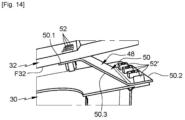
- the compression energy absorption device could be positioned elsewhere in the aircraft. More generally, the compression energy absorption device is configured to be positioned between first and second spaced-apart elements 32, 34, more precisely between first and second spaced-apart contact surfaces F32, F34, and to be subjected to compression forces oriented in a compression direction DC (visible on the Figure 4 ) intersecting with the first and second elements 32, 34.
- a compression direction DC visible on the Figure 4
- the first and second contact surfaces F32, F34 are substantially parallel to each other and substantially perpendicular to the compression direction DC.
- the first and second contact surfaces F32, F34 are not parallel to each other, and one of them is perpendicular to the compression direction DC.
- the first element 32 is chosen from a structure, a fuselage, a fairing or a tank of the aircraft; the second element 34 being different from the first element 32, spaced from the latter and chosen from a structure, a fuselage, a fairing or a tank of the aircraft.
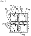
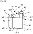
- Each compression energy absorption module 30 comprises several first conduits 36 spaced apart from each other, oriented in the compression direction DC and each having a first cross-section (perpendicular to the compression direction DC) as well as junction walls 38 parallel to the compression direction DC and connecting first conduits 36 so as to delimit, with the latter, at least one second conduit 40 which has a second cross-section (perpendicular to the compression direction DC).
- Each first conduit 36 has a side wall 42 and extends between first and second ends 42.1, 42.2 oriented respectively in the direction of the first and second elements 32, 34.
- the first conduits 36 of the same compression energy absorption module 30 all have the same cross-section.
- the first conduits 36 of the same compression energy absorption module 30 have different cross sections.
- the first cross sections of the first conduits 36 may be prismatic, square, rectangular, triangular, circular or semi-circular.
- the invention is not limited to these geometries for the first cross sections of the first conduits 36.
- a compression energy absorption module 30 comprises first conduits 36 having first cross sections in the shape of a circle or a semicircle which have substantially the same diameter.
- the first conduits 36 have, for example, a first cross-section of between 20 and 200 cm 2 .
- each junction wall 38 is substantially rectangular and extends between first and second edges 38.1, 38.2 oriented respectively in the direction of the first and second elements 32, 34 as well as the third and fourth edges 38.1, 38.2 connected to first conduits 36.
- junction walls 38 are planar. Some junction walls 38 may be non-planar and have at least one hollow shape to at least partially house a first conduit 36 of another compression energy absorption module 30.
- the junction walls 38 of the compression energy absorption modules 30 are oriented in two or three directions so as to obtain a network of orthogrid-type junction walls as illustrated in the figures 5 , 7 , 8 , 12 And 15 has 19 or isogrid type as shown in the Figure 6 .
- This solution allows to obtain a crushing of the first conduits 36 which ensures energy absorption and not a discharge of said first conduits 36.
- the junction walls 38 form an orthogrid type network and are oriented in a first direction parallel to the longitudinal direction and in a second direction perpendicular to the longitudinal direction.
- the compression energy absorption device comprises several compression energy absorption modules 30 positioned symmetrically with respect to the vertical longitudinal plane of symmetry of the aircraft.
- the first ends 42.1 of the first conduits 36 as well as the first edges 38.1 of the joining walls 38 of the same compression energy absorption module 30 are positioned in the same first plane or the same first almost flat surface.
- the second ends 42.2 of the first conduits 36 as well as the second edges 38.2 of the joining walls 38 of the same compression energy absorption module 30 are positioned in the same second plane or the same second almost flat surface.
- the joining walls 38 are connected to the first conduits 36 by any suitable means, such as by welding for example.
- the joining walls 38 and the first conduits 36 of a compression energy absorption module 30 are produced in one piece by an additive manufacturing process for example.
- junction walls 38 and the first conduits 36 of a compression energy absorption module 30 are made of aluminum alloy, in particular from aluminum alloy sheets.
- each second conduit 40 its second cross-section corresponds to an area delimited by the junction walls 38 and a part of the side walls 42 of the first conduits 36 and does not include the first cross-sections of the first conduits 36 bordering it.
- the second cross-section of the second conduit 40 is greater than that(s) of the first conduits 36. According to one configuration, the second cross-section of the second conduit 40 is at least twice greater than the first cross-section of each first conduit 36 bordering the second conduit 40. Such a compression energy absorption module makes it possible to absorb a greater quantity of energy.
- the second cross-section of the second conduit 40 is greater than the sum of the first cross-sections of the first conduits 36 bordering the second conduit 40 and less than 10 times the sum of the first cross-sections of the first conduits 36 bordering the second conduit 40.
- the junction walls 38 and the first conduits 36 of the same compression energy absorption module 30 are arranged so that the second conduit 40 has a prismatic, square, rectangular, triangular or circular cross-section.
- the invention is not limited to these geometries for the cross-sections of the second conduit 40.
- the compression energy absorption module 30 comprises at least one second conduit 40. According to another embodiment, the compression energy absorption module 30 comprises several second conduits 40. According to one arrangement, the second conduits 40 of the same compression energy absorption module 30 are all identical, as illustrated in the Figure 11 .
- the compression energy absorption module 30 comprises at least one second conduit 40 having a second triangular cross-section, the first conduits 36 being positioned at the apexes of the cross-section of each second conduit 40.
- the compression energy absorption module 30 comprises at least a second conduit 40 having a second cross-section bordered by first conduits 36 being spaced from the vertices of the cross-section of each second conduit 40.
- the compression energy absorption module 30 comprises at least one second conduit 40 which has a second cross-section bordered by first cylindrical and/or semi-cylindrical conduits 36.
- the first conduits 36 are positioned at the sides of the second cross-section and spaced from the vertices of this second cross-section.
- the compression energy absorption module 30 comprises, at the sides of the second conduit 40, two or three first cylindrical and/or semi-cylindrical conduits 36.
- the compression energy absorption module 30 comprises at least one second conduit 40 having a second square or rectangular cross-section.
- the compression energy absorption module 30 comprises at the sides of the second conduit 40, two or three first cylindrical and/or semi-cylindrical conduits 36.
- the second conduit 40 has a second cross-section of between 200 and 2000 cm 2 .
- the dimensions and the material(s) of the first conduits 36 and the junction walls 38 are determined so as to obtain a progressive crushing of the first conduits 36, promoting the absorption of energy and not a spillage of the latter.
- the compression energy absorption module 30 comprises at least one first end wall 44 configured to close the first end 42.1 of at least one first conduit 36 as well as at least one second end wall 46 configured to close the second end 42.2 of at least one first conduit 36.
- the first end wall 44 is configured so as to at least partially clear the second conduit 40.
- the second end wall 46 is configured so as to at least partially clear the second conduit 40.
- the compression energy absorption module 30 comprises at least one first end wall 44 configured to close the first end 42.1 of at least one first conduit 36 and at least partially clearing the second conduit 40 as well as at least one second end wall 46 configured to close the second end 42.2 of at least one first conduit 36 and at least partially clearing the second conduit 40.
- the compression energy absorption module 30 comprises one or more first end wall(s) 44 closing the first end 42.1 of all the first conduits 36 and at least partially clearing the second conduit 40 as well as one or more second end wall(s) 46 closing the second end 42.2 of all the first conduits 36 and at least partially clearing the second conduit 40.
- a first end wall 44 is configured to close the first ends 42.1 of several first conduits 36 of the compression energy absorption module 30.
- a second end wall 46 is configured to close the second ends 42.2 of several conduits 36 of the compression energy absorption module 30.
- the first end wall 44 is configured to close the first ends 42.1 of all the first conduits 36 of the compression energy absorption module 30.
- This first end wall 44 forms a frame delimited by an inner edge 44.1 as well as an outer edge 44.2 spaced from the inner edge 44.1 by a sufficient distance to close the first conduits 36 of the compression energy absorption module 30.
- the second end wall 46 is configured to close the second ends 42.2 of all the first conduits 36 of the compression energy absorption module 30.
- This second end wall 46 forms a frame delimited by an inner edge as well as an outer edge spaced from the inner edge by a sufficient distance to close the first conduits 36 of the compression energy absorption module 30.
- each of the first and second end walls 44, 46 can be formed from a single wall or from several juxtaposed walls.
- the first and second end walls 44, 46 are part of the compression energy absorption module 30 and are connected to the first conduits 36 and to the joining walls 38 by any suitable means, such as by welding for example.
- any suitable means such as by welding for example.
- the invention is not limited to this embodiment.
- at least one of the first and second end walls 44, 46 could not be part of the compression energy absorption module 30 and be integral with the first or second element 32, 34 between which said compression energy absorption module 30 is positioned.
- the compression energy absorption device comprises at least one attachment system 48 removably connecting each compression energy absorption module 30 to at least one element among the first and second elements 32, 34 between which said compression energy absorption module 30 is positioned.
- This attachment system 48 is configured to allow rapid assembly or disassembly of the compression energy absorption module 30.
- the compression energy absorption device comprises at least two compression energy absorption modules 30 of which at least one compression energy absorption module comprises at least one common junction wall 39 with another compression energy absorption module 30.
- one of the joining walls 38 of the compression energy absorption device comprises at least one system for attachment to at least one first end wall 44 and to at least one second end wall 46.
- the common joining wall 39 comprises at least one system for attachment to at least one first end wall 44 and to at least one second end wall 46.
- at least one of the joining walls 38 parallel to the common wall 39 comprises attachments to at least one first end wall 44 and to at least one second end wall 46.
- one of the joining walls 38 of the compression energy absorption module comprises at least one attachment system to at least one first end wall 44 and to at least one second end wall 46.
- each compression energy absorption module 30 comprises several attachment systems 48 for connecting it to the fuselage 12 (more particularly to the skin 20 of the fuselage 12) and/or to the ventral fairing 28.
- each compression energy absorption module 30 is connected to only one element among the first and second elements 32, 34.
- the first element 32 being offset upwards relative to the second element 34, each compression energy absorption module is suspended under the first element 32, namely the fuselage 12 or the tank 26.
- each compression energy absorption module 30 is only connected to the fuselage 12 and/or to the tank 26 and is not connected to the ventral fairing 28. According to this arrangement, each compression energy absorption module 30 is suspended under the fuselage 12. Insofar as each compression energy absorption module 30 is only connected to a single element among the fuselage 12 and the ventral fairing 28, it does not ensure any transmission of forces between the fuselage 12 and the ventral fairing 28, which makes it possible to simplify its design.
- each compression energy absorption module 30 is independent of the first and second elements 32, 34 (fuselage 12 or ventral fairing 28) between which it is positioned and connected to at least one of these first and second elements 32, 34 by the removable attachment system(s) 48.
- a removable connection it is meant that each compression energy absorption module 30 can be assembled or disassembled several times, without impacting the characteristics of the first and second elements 32, 34.
- each attachment system 48 is designed to be connected to the first or second element 32, 34 without any modification of the latter.
- each compression energy absorption module 30 is spaced from the first and second elements 32, 34.
- each attachment system 48 comprises an angle iron 50 which has a first wing 50.1 pressed against the first or second element 32, 34 and connected to the latter by at least one first connecting element 52, a second wing 50.2 pressed against the compression energy absorption module 30 and connected to the latter by at least one second connecting element 52' as well as a core 50.3 connecting the first and second wings 50.1, 50.2 so as to form a single Z-shaped part.
- At least one of the first and second connecting elements 52, 52' is removable and is in the form of a bolt for example.
- the invention is not limited to this embodiment for the attachment systems 48.
- the attachment systems could have a C-shaped section.
Landscapes
- Engineering & Computer Science (AREA)
- Mechanical Engineering (AREA)
- Aviation & Aerospace Engineering (AREA)
- General Engineering & Computer Science (AREA)
- Vibration Dampers (AREA)
- Connection Of Plates (AREA)
Applications Claiming Priority (1)
| Application Number | Priority Date | Filing Date | Title |
|---|---|---|---|
| FR2314132A FR3156752A1 (fr) | 2023-12-14 | 2023-12-14 | Aéronef comprenant au moins un dispositif démontable d’absorption d’énergie par compression |
Publications (1)
| Publication Number | Publication Date |
|---|---|
| EP4570648A1 true EP4570648A1 (de) | 2025-06-18 |
Family
ID=90363417
Family Applications (1)
| Application Number | Title | Priority Date | Filing Date |
|---|---|---|---|
| EP24218929.8A Pending EP4570648A1 (de) | 2023-12-14 | 2024-12-11 | Flugzeug mit mindestens einer abnehmbaren druckenergieabsorptionsvorrichtung |
Country Status (4)
| Country | Link |
|---|---|
| US (1) | US20250196989A1 (de) |
| EP (1) | EP4570648A1 (de) |
| CN (1) | CN120156681A (de) |
| FR (1) | FR3156752A1 (de) |
Families Citing this family (1)
| Publication number | Priority date | Publication date | Assignee | Title |
|---|---|---|---|---|
| EP4574648A1 (de) * | 2023-12-22 | 2025-06-25 | Airbus Operations, S.L.U. | Flugzeugrumpfabschnitt |
Citations (4)
| Publication number | Priority date | Publication date | Assignee | Title |
|---|---|---|---|---|
| EP1426289A1 (de) | 2002-12-04 | 2004-06-09 | Kawasaki Jukogyo Kabushiki Kaisha | Crashresistente Hubschrauberzelle und der dabei eingesetzte Stossdämpfer |
| US20090184200A1 (en) * | 2008-01-18 | 2009-07-23 | The Boeing Company | Vibration damping for wing-to-body aircraft fairing |
| EP2505490A1 (de) * | 2011-03-28 | 2012-10-03 | Airbus Opérations SAS | Stoßdämpfer |
| US9637212B2 (en) | 2014-04-10 | 2017-05-02 | The Boeing Company | Aircraft body mounted energy absorbing rub strip |
Family Cites Families (8)
| Publication number | Priority date | Publication date | Assignee | Title |
|---|---|---|---|---|
| US4593870A (en) * | 1983-09-09 | 1986-06-10 | Bell Helicopter Textron Inc. | Energy absorbing composite aircraft structure |
| DE4313592C2 (de) * | 1993-04-26 | 2000-02-17 | Daimler Chrysler Aerospace | Großraumflugzeug |
| DE602005011634D1 (de) * | 2005-10-21 | 2009-01-22 | Agusta Spa | Verformbare Bodenunterstruktur für einen Hubschrauber |
| US8376275B2 (en) * | 2006-12-08 | 2013-02-19 | The Boeing Company | Energy absorbing structure for aircraft |
| US9163369B2 (en) * | 2009-04-07 | 2015-10-20 | Valmount Highway Technology Limited | Energy absorption device |
| JP5129827B2 (ja) * | 2010-02-12 | 2013-01-30 | 三菱重工業株式会社 | 衝撃吸収構造体及び衝撃吸収構造体の製造方法、並びに、移動体 |
| US10704638B2 (en) * | 2016-04-26 | 2020-07-07 | Ford Global Technologies, Llc | Cellular structures with twelve-cornered cells |
| EP4574648A1 (de) * | 2023-12-22 | 2025-06-25 | Airbus Operations, S.L.U. | Flugzeugrumpfabschnitt |
-
2023
- 2023-12-14 FR FR2314132A patent/FR3156752A1/fr active Pending
-
2024
- 2024-12-11 CN CN202411813996.8A patent/CN120156681A/zh active Pending
- 2024-12-11 US US18/976,689 patent/US20250196989A1/en active Pending
- 2024-12-11 EP EP24218929.8A patent/EP4570648A1/de active Pending
Patent Citations (5)
| Publication number | Priority date | Publication date | Assignee | Title |
|---|---|---|---|---|
| EP1426289A1 (de) | 2002-12-04 | 2004-06-09 | Kawasaki Jukogyo Kabushiki Kaisha | Crashresistente Hubschrauberzelle und der dabei eingesetzte Stossdämpfer |
| US20090184200A1 (en) * | 2008-01-18 | 2009-07-23 | The Boeing Company | Vibration damping for wing-to-body aircraft fairing |
| EP2505490A1 (de) * | 2011-03-28 | 2012-10-03 | Airbus Opérations SAS | Stoßdämpfer |
| US9637212B2 (en) | 2014-04-10 | 2017-05-02 | The Boeing Company | Aircraft body mounted energy absorbing rub strip |
| EP3129220B1 (de) * | 2014-04-10 | 2020-09-09 | The Boeing Company | Am flugzeugkörper montiertes energieabsorbierendes reibband |
Also Published As
| Publication number | Publication date |
|---|---|
| FR3156752A1 (fr) | 2025-06-20 |
| CN120156681A (zh) | 2025-06-17 |
| US20250196989A1 (en) | 2025-06-19 |
Similar Documents
| Publication | Publication Date | Title |
|---|---|---|
| EP3674204B1 (de) | Zwei aneinander befestigte flügel eines luftfahrzeugs | |
| FR3040076A1 (fr) | Ensemble moteur pour aeronef comprenant une structure primaire de mat d'accrochage equipee d'une extension de caisson comprenant deux parties en forme globale d'arceau | |
| FR3065441A1 (fr) | Ensemble pour aeronef comprenant une structure primaire de mat d'accrochage fixee a un caisson de voilure a l'aide d'une liaison boulonnee | |
| FR2914616A1 (fr) | Soubassement de vehicule automobile | |
| FR3098793A1 (fr) | Ensemble propulseur comprenant une attache moteur avant améliorée et aéronef comprenant au moins un tel ensemble propulseur | |
| EP4294706B1 (de) | Untergestellstruktur für ein kraftfahrzeug mit einem seitlichen verstärkungsteil | |
| FR3073824A1 (fr) | Ensemble pour aeronef comprenant une structure primaire de mat d'accrochage fixee a un caisson de voilure par des attaches partiellement enterrees dans la structure primaire | |
| EP4570648A1 (de) | Flugzeug mit mindestens einer abnehmbaren druckenergieabsorptionsvorrichtung | |
| FR3023250A1 (fr) | Traverse transversale de renfort amelioree a rupture programmee | |
| EP4570647A1 (de) | Vorrichtung zur absorption von energie durch kompression, luftfahrzeug, das mindestens eine solche vorrichtung umfasst | |
| WO2007066026A1 (fr) | Mur de cloisonnement pour carénage ventral d'aéronef et aéronef muni d'un carénage ventral | |
| EP1571079B1 (de) | Rumpfholm für ein Flugzeug und Flügelmittelkasten mit einem solchen Rumpfholm | |
| EP3699091B1 (de) | Primärstruktur eines flugzeugtriebwerkträgers, die mindestens eine querversteifung mit zwei diagonal angeordneten streben umfasst, und luftfahrzeug mit einer solchen primärstruktur | |
| FR3113484A1 (fr) | Ensemble propulseur d’aéronef comprenant des bielles d’une attache moteur avant reliées directement à un renfort transversal avant d’une structure primaire d’un mât d’aéronef | |
| FR3052745A1 (fr) | Mat d'aeronef comprenant au moins un cadre lateral en forme de treillis et aeronef comprenant ledit mat | |
| EP3057852B1 (de) | Karosseriestruktur für ein kraftfahrzeug mit einer wärmekraftmaschine oder ein elektromotorfahrzeug | |
| FR3100226A1 (fr) | Ensemble propulseur d’aéronef comprenant une attache moteur arrière à faible encombrement transversal et aéronef comprenant au moins un tel ensemble propulseur | |
| FR2887522A1 (fr) | Ensemble pour aeronef comprenant un element de voilure ainsi qu'un mat d'accrochage | |
| FR3159588A1 (fr) | Dispositif d’absorption d’énergie par compression comprenant des tubes d’absorption de forme étoilée, aéronef comportant au moins un tel dispositif | |
| FR3105151A1 (fr) | Structure arriere de caisse de vehicule automobile a plancher polymere et support de batterie | |
| FR3013285A1 (fr) | Structure de pare-chocs de vehicule et vehicule correspondant | |
| EP4177157B1 (de) | Flugzeug mit gelenkig verbundenen und im kabinenboden integrierten schienen | |
| FR2984273A1 (fr) | Support de plancher d'aeronef | |
| EP4613649A1 (de) | Primärstruktur eines flugzeugpylons mit dreieckigem querschnitt, flugzeug mit mindestens einer solchen primärstruktur | |
| FR3136224A1 (fr) | Aéronef comprenant une attache voilure pour aile épaisse |
Legal Events
| Date | Code | Title | Description |
|---|---|---|---|
| PUAI | Public reference made under article 153(3) epc to a published international application that has entered the european phase |
Free format text: ORIGINAL CODE: 0009012 |
|
| STAA | Information on the status of an ep patent application or granted ep patent |
Free format text: STATUS: REQUEST FOR EXAMINATION WAS MADE |
|
| STAA | Information on the status of an ep patent application or granted ep patent |
Free format text: STATUS: EXAMINATION IS IN PROGRESS |
|
| 17P | Request for examination filed |
Effective date: 20241211 |
|
| AK | Designated contracting states |
Kind code of ref document: A1 Designated state(s): AL AT BE BG CH CY CZ DE DK EE ES FI FR GB GR HR HU IE IS IT LI LT LU LV MC ME MK MT NL NO PL PT RO RS SE SI SK SM TR |
|
| 17Q | First examination report despatched |
Effective date: 20250521 |