EP4570660A1 - Support d'article polyvalent - Google Patents
Support d'article polyvalent Download PDFInfo
- Publication number
- EP4570660A1 EP4570660A1 EP24213394.0A EP24213394A EP4570660A1 EP 4570660 A1 EP4570660 A1 EP 4570660A1 EP 24213394 A EP24213394 A EP 24213394A EP 4570660 A1 EP4570660 A1 EP 4570660A1
- Authority
- EP
- European Patent Office
- Prior art keywords
- seat back
- arm
- back holder
- mount
- recess
- Prior art date
- Legal status (The legal status is an assumption and is not a legal conclusion. Google has not performed a legal analysis and makes no representation as to the accuracy of the status listed.)
- Pending
Links
Images


Classifications
-
- B—PERFORMING OPERATIONS; TRANSPORTING
- B64—AIRCRAFT; AVIATION; COSMONAUTICS
- B64D—EQUIPMENT FOR FITTING IN OR TO AIRCRAFT; FLIGHT SUITS; PARACHUTES; ARRANGEMENT OR MOUNTING OF POWER PLANTS OR PROPULSION TRANSMISSIONS IN AIRCRAFT
- B64D11/00—Passenger or crew accommodation; Flight-deck installations not otherwise provided for
- B64D11/06—Arrangements of seats, or adaptations or details specially adapted for aircraft seats
- B64D11/0638—Arrangements of seats, or adaptations or details specially adapted for aircraft seats with foldable tables, trays or cup holders
-
- B—PERFORMING OPERATIONS; TRANSPORTING
- B60—VEHICLES IN GENERAL
- B60N—SEATS SPECIALLY ADAPTED FOR VEHICLES; VEHICLE PASSENGER ACCOMMODATION NOT OTHERWISE PROVIDED FOR
- B60N3/00—Arrangements or adaptations of other passenger fittings, not otherwise provided for
- B60N3/10—Arrangements or adaptations of other passenger fittings, not otherwise provided for of receptacles for food or beverages, e.g. refrigerated
- B60N3/102—Arrangements or adaptations of other passenger fittings, not otherwise provided for of receptacles for food or beverages, e.g. refrigerated storable or foldable in a non-use position
Definitions
- the present disclosure relates generally to holders, and, more particularly, to multi-purpose holders on the back of seats.
- Aircraft cabins typically include a seat back-mounted tray.
- aircraft economy seats do not typically have the stowage options and space available to premium class seats.
- Passengers may try to look for non-optimal options for cramming their belongings for storage, such as under the seat.
- the seat back holder may include a mount.
- the seat back holder may include a body coupled to the mount. The body may be configured to repeatably rotate around an axis between a mated position adjacent to the mount and a deployed position via a pivoting mechanism of the seat back holder.
- the body may include a plate defining a recess configured to receive an object.
- the plate may include a first arm and a second arm on opposing sides of the recess.
- the body may include a void defined by, and passing through, at least one of the first arm or the second arm.
- the first arm and the second arm may each include a tab extending up from an inner-top surface of the body.
- each of the tabs may include a magnet configured to mate to a corresponding mount magnet on the mount.
- the recess may be curved and thereby configured to receive a bottle neck of a bottle.
- the seat back holder may have a width that is less than 8 inches wide and the body may have a length less than 6 inches.
- the body may include at least one of nylon material or thermoplastic material.
- the pivoting mechanism may include a shaft.
- the pivoting mechanism may include at least one spring configured to bias the body towards the mated position from the deployed position.
- a body for a seat back holder is disclosed in accordance with one or more illustrative embodiments of the present disclosure.
- the body may be configured to repeatably rotate around an axis between a mated position and a deployed position via a pivoting mechanism.
- the body may include a plate defining a recess configured to receive an object.
- embodiments herein are directed to a item holder (e.g., seat back holder) configured to be mounted to the back of a seat (e.g., aircraft seat) and simultaneously hold a variety of items while only taking up a relatively small amount of space compared to conventional fold down trays.
- Embodiments may leverage space available adjacent to the meal table tray to provide an option which is compact and which provides multiple stowing options such as for a bottle, eyeglasses, a hat, a strapped bag, a display device such as a cell phone, and/or more.
- Embodiments herein may serve as a one stop solution for those passengers who are interested in keeping/parking a few of their belongings such as phones, headphones, caps, handbags, spectacles and beverage/water bottles during a long-haul flight in economy class.
- Benefits may include: helping the user to free themself by stowing their belongings rather than keeping them in cabin luggage or under the baggage bar; helping the user to achieve a comfort profile while watching the mobile platforms; staying in the deployed position using the weight of the stowed items themselves; and/or providing a relatively low cost and easily retrofittable design that may only require minimal changes to the seat back shell.
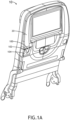
- FIG. 1A illustrates a system 10 comprising a seat back 20 coupled to a seat back holder 100 in a mated position, in accordance with one or more embodiments of the present disclosure.
- the mated position may include the body 104 being mated, adjacent, coupled, and/or the like to the mount 102.
- they may both be configured to be aligned in a vertical orientation, parallel to the seat back 20 by default.
- the seat back holder 100 may include a mount 102 and a body 104.
- the mount 102 may be configured to mounted (e.g., be fastened via holes not shown, glued, and/or the like) to the seat back 20.
- the body 104 may be coupled to the mount 102.
- the body 104 and/or mount 102 may include any material, such as materials suitable for 3D printing.
- the body 104 may include at least one of nylon material or thermoplastic material.
- the seat back 20 itself may include a seat back recess for installing the seat back holder 100 to allow it to be more flush with the seat back 20. This may also allow for upgrading and/or replacement when broken.
- the mount 102 may be integrated into the seat back 20, such as the mount 102 being an integral, permanent (non-replaceable) designed portion of the entire seat back 20.
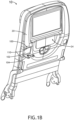
- FIG. 1B illustrates the seat back holder 100 in a deployed position (e.g., for use by a user who pulls it down), in accordance with one or more embodiments of the present disclosure.
- the mount 102 may include mount magnets 110 for holding the body 104 in place in a mated position.
- the seat back holder 100 may be configured to be located in one or more locations of the seat back 20.
- the seat back holder 100 may be in a first location 22 that is adjacent and/or above and center-left of a tray.
- the seat back holder 100 may be in a (second) location 24 that is adjacent and/or centered above a tray.
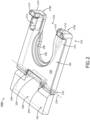
- FIG. 2 illustrates a view of a seat back holder 100, in accordance with one or more embodiments of the present disclosure.
- the body 104 may be configured to repeatably rotate (back and forth as it is pulled down for selective use) around an axis 220. This rotation may occur between a mated position adjacent to the mount and a deployed position via a pivoting mechanism 226 of the seat back holder 100.
- the body 104 may comprise a plate 200 that defines a recess 222.
- the recess 222 may be configured to receive an object 508, which may be at a front of the body 104 for receiving the object 508 at the front, such as towards a center of the plate 200.
- the plate 200 may include a first arm 218a and a second arm 218b. These arms 218a, 218b may be located on opposing sides of the recess 222.
- the body 104 of the seat back holder may include a void 214, which may be configured to hold eyeglasses or any other object that fits.
- the void 214 may be defined by, and pass through, at least one of the first arm 218a or the second arm 218b.
- the void 214 may be a hole passing through the second arm 218b, which may be on the right side.
- the first arm 218a and the second arm 218b of the seat back holder may each include a tab 210. These tabs 210 may extend up from the inner-top surface 216 of the body 104. Each of the tabs 210 may be configured to stop an object (e.g., cell phone) from sliding off the inner-top surface 216. This may be useful for mounting a cell-phone, or other display device with a display for hands-free storage, and/or viewing.
- an object e.g., cell phone
- Each of the tabs 210 of the seat back holder may include a magnet 212.
- the magnet 212 may be configured to mate to a corresponding mount magnet 110 on the mount 102, such as may prevent the body 104 from falling down unintended.
- the recess 222 of the seat back holder may be curved, such as including a curved surface 208.
- the curved surface 208 may be configured to receive, support, and hold a bottle neck of a bottle 508.
- the recess 222 may include a front curved surface 206 adjacent to the curved surface 208.
- the pivoting mechanism 226 may include at least one spring 204.
- the springs 204 may provide a relatively low spring force which is configured to be overcome by a weight of an item that is stowed.
- the spring may include a torsion spring configured to provide a torsion force within 3 times the force needed to move the body 104 up from a level/horizontal angle relative to gravity when on a flat runway, which may be at or near the deployed position. This may be higher than a maximum force needed to resist gravity when no item is on the body 104.
- the pivoting mechanism 226 may include a shaft 202 for rotating.
- the pivoting mechanism 226 may include springs 204 (e.g., one on each side of the mount 102).
- the springs 204 may be configured to bias the body 104 to rotate towards the mated position from the deployed position.
- the pivoting mechanism 226 may be configured to rotate any angle range, such as between 30 degree and 100 degrees.
- the tabs 210 may be at a first front end 224 of the body 104, opposite an end of the pivoting mechanism 226.
- the mated position may include an inner-top surface 216 of the body 104 being mated, adjacent, coupled, proximate, and/or the like to an inner mount surface of the mount 102.
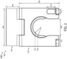
- FIG. 3 illustrates a top view of a seat back holder 100, in accordance with one or more embodiments of the present disclosure.
- the seat back holder 100 may be less than 8 inches in width 302 and the body 104 may be less than 6 inches in body length 306.
- any one of the dimensions for any component (e.g., body 104) herein may be used in any embodiment, individually and/or in combination with multiple or all of any other dimensions. However, such dimensions are not necessarily limiting and a person of skill in the art will understand that concepts and components herein may extend to other dimensions, shapes, configurations and the like. For conciseness, any dimension may be extended in any embodiment to be within 50% of any dimension herein, although even then, the dimensions listed are not necessarily limited to within 50% in every embodiment. As an illustrative example, an "element of height 1.0 inches" may include embodiments of the element with a height between 0.5 to 1.5 inches.
- One or more of following dimensions may be used, alone or in combination (within 50% of these dimensions): a width 302 of 2.25 inches, a mount length 304 of 0.85 inches, a body length 306 of 2.50 inches, an arm width 314 of 0.7 inches, a recess front entrance width 308 of 1 inch, a 30 of inches, a void width 312 of 0.3 inches, and/or a void length 310 of 0.5 inches.
- the front curved surface 206 may be any size, such as within 50% of recess radius 316 of 0.5 inches, and an upper level recess radius 318 of 0.65 inches.
- FIG. 4 illustrates a front view of a body 104 of a seat back holder 100, in accordance with one or more embodiments of the present disclosure.
- One or more of following dimensions may be used, alone or in combination (within 50% of these dimensions): a total seat back holder height 404 of 0.5 inches, and/or a plate thickness 402 of 0.25 inches.
- FIG. 5A illustrates an example use case 500 of a seat back holder 100 supporting a bottle 508 (e.g., standard bottle with a bottle neck and twist-off cap) and a display device 506 (e.g., mobile cell phone), in accordance with one or more embodiments of the present disclosure.
- FIG. 5B illustrates an example use case 502 of a seat back holder 100 supporting a bottle 508 and eyeglasses 510, in accordance with one or more embodiments of the present disclosure.
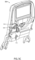
- FIG. 5C illustrates an example use case 504 of a seat back holder 100 supporting eyeglasses 510 and a strapped bag 512 (e.g., purse), in accordance with one or more embodiments of the present disclosure.
- a strapped bag 512 e.g., purse
- a letter following a reference numeral is intended to reference an embodiment of the feature or element that may be similar, but not necessarily identical, to a previously described element or feature bearing the same reference numeral (e.g., 1, 1a, 1b).
- reference numeral e.g. 1, 1a, 1b
- Such shorthand notations are used for purposes of convenience only and should not be construed to limit the disclosure in any way unless expressly stated to the contrary.
- any reference to “in embodiments”, “one embodiment” or “some embodiments” means that a particular element, feature, structure, or characteristic described in connection with the embodiment is included in at least one embodiment disclosed herein.
- the appearances of the phrase “in some embodiments” in various places in the specification are not necessarily all referring to the same embodiment, and embodiments may include one or more of the features expressly described or inherently present herein, or any combination or sub-combination of two or more such features, along with any other features which may not necessarily be expressly described or inherently present in the instant disclosure.
- embodiments of the methods disclosed herein may include one or more of the steps described herein. Further, such steps may be carried out in any desired order and two or more of the steps may be carried out simultaneously with one another. Two or more of the steps disclosed herein may be combined in a single step, and in some embodiments, one or more of the steps may be carried out as two or more sub-steps. Further, other steps or sub-steps may be carried in addition to, or as substitutes to one or more of the steps disclosed herein.
Landscapes
- Engineering & Computer Science (AREA)
- Physics & Mathematics (AREA)
- Thermal Sciences (AREA)
- Transportation (AREA)
- Mechanical Engineering (AREA)
- Aviation & Aerospace Engineering (AREA)
- Vehicle Step Arrangements And Article Storage (AREA)
Applications Claiming Priority (2)
| Application Number | Priority Date | Filing Date | Title |
|---|---|---|---|
| IN202311085802 | 2023-12-15 | ||
| US18/614,243 US20250197008A1 (en) | 2023-12-15 | 2024-03-22 | Multipurpose item holder |
Publications (1)
| Publication Number | Publication Date |
|---|---|
| EP4570660A1 true EP4570660A1 (fr) | 2025-06-18 |
Family
ID=93563569
Family Applications (1)
| Application Number | Title | Priority Date | Filing Date |
|---|---|---|---|
| EP24213394.0A Pending EP4570660A1 (fr) | 2023-12-15 | 2024-11-15 | Support d'article polyvalent |
Country Status (1)
| Country | Link |
|---|---|
| EP (1) | EP4570660A1 (fr) |
Citations (8)
| Publication number | Priority date | Publication date | Assignee | Title |
|---|---|---|---|---|
| US1606064A (en) * | 1926-11-09 | Bottle or article holder | ||
| US1757521A (en) * | 1928-05-24 | 1930-05-06 | William H Gebhards | Milk-bottle holder |
| US2791392A (en) * | 1953-01-26 | 1957-05-07 | Charles A Black | Bottle holder |
| DE3626901A1 (de) * | 1986-08-08 | 1988-02-11 | Porsche Ag | Haltevorrichtung fuer ein trinkgefaess, wie einen becher, eine dose oder dergleichen |
| US20050035254A1 (en) * | 2003-08-11 | 2005-02-17 | Moyer Scott A. | Cam activated extendable cupholder |
| DE102008061110A1 (de) * | 2008-12-09 | 2010-06-10 | GM Global Technology Operations, Inc., Detroit | Vorrichtung zum lösbaren Halten eines Gegenstandes insbesondere für Flüssigkeitsbehälter in Fahrzeugen |
| DE102014117549A1 (de) * | 2013-11-29 | 2015-06-03 | Recaro Aircraft Seating Gmbh & Co. Kg | Flugzeugsitzvorrichtung |
| KR20230057617A (ko) * | 2021-10-22 | 2023-05-02 | 김용은 | 다용도 홀더 |
-
2024
- 2024-11-15 EP EP24213394.0A patent/EP4570660A1/fr active Pending
Patent Citations (8)
| Publication number | Priority date | Publication date | Assignee | Title |
|---|---|---|---|---|
| US1606064A (en) * | 1926-11-09 | Bottle or article holder | ||
| US1757521A (en) * | 1928-05-24 | 1930-05-06 | William H Gebhards | Milk-bottle holder |
| US2791392A (en) * | 1953-01-26 | 1957-05-07 | Charles A Black | Bottle holder |
| DE3626901A1 (de) * | 1986-08-08 | 1988-02-11 | Porsche Ag | Haltevorrichtung fuer ein trinkgefaess, wie einen becher, eine dose oder dergleichen |
| US20050035254A1 (en) * | 2003-08-11 | 2005-02-17 | Moyer Scott A. | Cam activated extendable cupholder |
| DE102008061110A1 (de) * | 2008-12-09 | 2010-06-10 | GM Global Technology Operations, Inc., Detroit | Vorrichtung zum lösbaren Halten eines Gegenstandes insbesondere für Flüssigkeitsbehälter in Fahrzeugen |
| DE102014117549A1 (de) * | 2013-11-29 | 2015-06-03 | Recaro Aircraft Seating Gmbh & Co. Kg | Flugzeugsitzvorrichtung |
| KR20230057617A (ko) * | 2021-10-22 | 2023-05-02 | 김용은 | 다용도 홀더 |
Similar Documents
| Publication | Publication Date | Title |
|---|---|---|
| US8934063B2 (en) | In-flight entertainment system | |
| US9468302B2 (en) | Armrest expansion device | |
| EP2799338B1 (fr) | Table à plateau configurable | |
| US10414313B2 (en) | Hidden foldable tray table | |
| EP3313691B1 (fr) | Ensemble bras de support | |
| US20170283067A1 (en) | Tray Table Deployable from Lower Seatback Area | |
| EP2981464B1 (fr) | Structure de support à fixer à une tablette pour un siège passager, tablette pour un siège passager, et siège passager | |
| US12280873B2 (en) | Portable electronic device holder for seat | |
| US20110126739A1 (en) | Portable, Collapsible, Workstation Tray Table Apparatus | |
| US9776721B2 (en) | Retention of objects relative to an airplane cabin window frame | |
| CN205468698U (zh) | 组合式杯架和存储箱 | |
| EP3230162B1 (fr) | Support de dispositif rétractable pour siège d'aéronef | |
| US20130062382A1 (en) | Holder Apparatus For Beverage Containers And Other Objects For Use With An Airplane Cabin Window Frame Assembly And Installation Method For Same | |
| US10391951B2 (en) | Support systems for portable electronic devices | |
| US10744921B2 (en) | Portable electronic device holder for tray tables | |
| US10532816B2 (en) | Amenities modules | |
| WO2020263262A1 (fr) | Surface de support pouvant être déployée et formée à partir d'une enveloppe supérieure | |
| US20110240810A1 (en) | Cup Holder | |
| US8668258B2 (en) | Arm rest | |
| EP4570660A1 (fr) | Support d'article polyvalent | |
| US20250197008A1 (en) | Multipurpose item holder | |
| US12269394B2 (en) | Adjustable device holder | |
| US12172581B2 (en) | Deployable personal entertainment device holder | |
| JP6166477B2 (ja) | 機内持ち込み乗客シート | |
| US20180271242A1 (en) | Combination travel viewing platform and protective carrying case for smart phones and tablets |
Legal Events
| Date | Code | Title | Description |
|---|---|---|---|
| PUAI | Public reference made under article 153(3) epc to a published international application that has entered the european phase |
Free format text: ORIGINAL CODE: 0009012 |
|
| STAA | Information on the status of an ep patent application or granted ep patent |
Free format text: STATUS: THE APPLICATION HAS BEEN PUBLISHED |
|
| AK | Designated contracting states |
Kind code of ref document: A1 Designated state(s): AL AT BE BG CH CY CZ DE DK EE ES FI FR GB GR HR HU IE IS IT LI LT LU LV MC ME MK MT NL NO PL PT RO RS SE SI SK SM TR |
|
| STAA | Information on the status of an ep patent application or granted ep patent |
Free format text: STATUS: REQUEST FOR EXAMINATION WAS MADE |
|
| 17P | Request for examination filed |
Effective date: 20251124 |
|
| STAA | Information on the status of an ep patent application or granted ep patent |
Free format text: STATUS: EXAMINATION IS IN PROGRESS |
|
| 17Q | First examination report despatched |
Effective date: 20260311 |