EP4570951A1 - Procédé de fabrication d'une électrode poreuse - Google Patents
Procédé de fabrication d'une électrode poreuse Download PDFInfo
- Publication number
- EP4570951A1 EP4570951A1 EP23216901.1A EP23216901A EP4570951A1 EP 4570951 A1 EP4570951 A1 EP 4570951A1 EP 23216901 A EP23216901 A EP 23216901A EP 4570951 A1 EP4570951 A1 EP 4570951A1
- Authority
- EP
- European Patent Office
- Prior art keywords
- particles
- slurry
- polymeric binder
- porous electrode
- binder material
- Prior art date
- Legal status (The legal status is an assumption and is not a legal conclusion. Google has not performed a legal analysis and makes no representation as to the accuracy of the status listed.)
- Pending
Links
Images

Classifications
-
- C—CHEMISTRY; METALLURGY
- C25—ELECTROLYTIC OR ELECTROPHORETIC PROCESSES; APPARATUS THEREFOR
- C25B—ELECTROLYTIC OR ELECTROPHORETIC PROCESSES FOR THE PRODUCTION OF COMPOUNDS OR NON-METALS; APPARATUS THEREFOR
- C25B1/00—Electrolytic production of inorganic compounds or non-metals
- C25B1/01—Products
- C25B1/02—Hydrogen or oxygen
- C25B1/04—Hydrogen or oxygen by electrolysis of water
-
- C—CHEMISTRY; METALLURGY
- C25—ELECTROLYTIC OR ELECTROPHORETIC PROCESSES; APPARATUS THEREFOR
- C25B—ELECTROLYTIC OR ELECTROPHORETIC PROCESSES FOR THE PRODUCTION OF COMPOUNDS OR NON-METALS; APPARATUS THEREFOR
- C25B11/00—Electrodes; Manufacture thereof not otherwise provided for
- C25B11/02—Electrodes; Manufacture thereof not otherwise provided for characterised by shape or form
- C25B11/03—Electrodes; Manufacture thereof not otherwise provided for characterised by shape or form perforated or foraminous
- C25B11/031—Porous electrodes
-
- C—CHEMISTRY; METALLURGY
- C25—ELECTROLYTIC OR ELECTROPHORETIC PROCESSES; APPARATUS THEREFOR
- C25B—ELECTROLYTIC OR ELECTROPHORETIC PROCESSES FOR THE PRODUCTION OF COMPOUNDS OR NON-METALS; APPARATUS THEREFOR
- C25B11/00—Electrodes; Manufacture thereof not otherwise provided for
- C25B11/04—Electrodes; Manufacture thereof not otherwise provided for characterised by the material
-
- C—CHEMISTRY; METALLURGY
- C25—ELECTROLYTIC OR ELECTROPHORETIC PROCESSES; APPARATUS THEREFOR
- C25B—ELECTROLYTIC OR ELECTROPHORETIC PROCESSES FOR THE PRODUCTION OF COMPOUNDS OR NON-METALS; APPARATUS THEREFOR
- C25B11/00—Electrodes; Manufacture thereof not otherwise provided for
- C25B11/04—Electrodes; Manufacture thereof not otherwise provided for characterised by the material
- C25B11/042—Electrodes formed of a single material
-
- C—CHEMISTRY; METALLURGY
- C25—ELECTROLYTIC OR ELECTROPHORETIC PROCESSES; APPARATUS THEREFOR
- C25B—ELECTROLYTIC OR ELECTROPHORETIC PROCESSES FOR THE PRODUCTION OF COMPOUNDS OR NON-METALS; APPARATUS THEREFOR
- C25B11/00—Electrodes; Manufacture thereof not otherwise provided for
- C25B11/04—Electrodes; Manufacture thereof not otherwise provided for characterised by the material
- C25B11/042—Electrodes formed of a single material
- C25B11/048—Organic compounds
-
- H—ELECTRICITY
- H01—ELECTRIC ELEMENTS
- H01M—PROCESSES OR MEANS, e.g. BATTERIES, FOR THE DIRECT CONVERSION OF CHEMICAL ENERGY INTO ELECTRICAL ENERGY
- H01M4/00—Electrodes
- H01M4/02—Electrodes composed of, or comprising, active material
- H01M4/62—Selection of inactive substances as ingredients for active masses, e.g. binders, fillers
- H01M4/621—Binders
- H01M4/622—Binders being polymers
-
- H—ELECTRICITY
- H01—ELECTRIC ELEMENTS
- H01M—PROCESSES OR MEANS, e.g. BATTERIES, FOR THE DIRECT CONVERSION OF CHEMICAL ENERGY INTO ELECTRICAL ENERGY
- H01M4/00—Electrodes
- H01M4/02—Electrodes composed of, or comprising, active material
- H01M2004/021—Physical characteristics, e.g. porosity, surface area
Definitions
- the present invention is related to a method of producing a porous electrode, such as a porous electrode comprising an electrochemically active material.
- the present invention is further related to a porous electrode, in particular as obtained by methods of the invention.
- Water electrolysis is an electrochemical process that involves the decomposition of water into its constituent elements, hydrogen and oxygen, using an external electrical energy source. It is a promising technology with a wide range of applications, including hydrogen production for clean fuel, energy storage, and industrial processes. Water electrolysis plays an important role in the development of sustainable energy solutions. As a clean and renewable process, it enables the production of hydrogen, a versatile energy carrier that can be used in fuel cells, industrial processes, and as a clean transportation fuel. When coupled with renewable energy sources like solar and wind, water electrolysis offers an efficient method for energy storage and grid balancing, addressing the intermittency of renewables.
- Electrolysis is carried out in an electrolysis cell.
- An electrolysis cell consists of a membrane, an anode and a cathode which are immersed in an electrolyte. When an electric current is applied through an external power source, redox reactions occur at the electrodes.
- solid electrolytes include proton exchange membranes, anion exchange membrane and solid oxide ceramic electrolytes.
- liquid electrolytes include aqueous alkaline solutions and aqueous acidic solutions.
- PEM electrolysis In proton exchange membrane electrolysis, a proton exchange membrane (PEM) separates the anode and cathode compartments, and conducts protons. PEM electrolysis has gained importance due to its ability to operate at relatively low temperatures and pressures. The PEM electrolysis technology offers fast response times, high efficiency, and good controllability. However, the reliance on expensive platinum-based catalysts poses cost challenges for widespread adoption.
- Solid oxide ceramic electrolytes are used in solid oxide electrolysis cells (SOECs), which operate at high temperatures.
- SOECs solid oxide electrolysis cells
- the high-temperature operation allows for efficient heat integration with other industrial processes.
- SOECs require robust materials that can withstand these high temperatures.
- an aqueous solution comprising a strong acid such as sulphuric acid and hydrochloric acid is used as the electrolyte.
- a strong acid such as sulphuric acid and hydrochloric acid
- managing concentrated acid electrolytes poses corrosion problems, and the technical solutions are expensive.
- alkaline electrolysis an aqueous solution comprising a strong alkaline electrolyte solution such as potassium hydroxide is used.
- Alkaline electrolysis is one of the earliest and most mature electrolysis technologies. It typically operates at relatively elevated temperatures (60-90 °C) and pressures up to 30 bar.
- typically used electrodes include nickel-based electrodes and iron-based electrodes. The process is characterized by its relatively low capital cost, long-term stability, and scalability, making it suitable for large-scale hydrogen production.
- Electrodes for electrolysis cells used in industrial alkaline electrolysis systems include electrodes based on nickel deposited on steel, such as steel meshes coated with nickel, and solid nickel, such as nickel stretched metal, nickel wire meshes and nickel foams.
- these electrodes tend to have limited catalytic activity, i.e. limited conversion rates of water into hydrogen and oxygen at a given power input to the cell, and are often either rigid and/or brittle.
- Freestanding ⁇ m-thin nanomesh electrodes exceeding 100x current density enhancement for high-throughput electrochemical applications N. Plankensteiner, R. Rupp et al., Materials Today Energy, vol. 30, 2022, 101172 discloses the fabrication of a freestanding metal electrodes having a thickness of a few micrometers, for use in water electrolysis.
- the electrode is a three-dimensional (3D) porous nanomesh consisting of a 3D-network of regular interconnected nanowires.
- the nanomesh has a high surface area and a high porosity of between 85 % and 97 %.
- a porous support structure is required to ensure that the nanowire-network is mechanically stable while maintaining its accessibility from all sides to allow for water and gas transport.
- WO99/45604 discloses a method for preparing an electrode film, comprising applying a mixture comprising an anodic or cathode active material, a polymer and a carrier solvent to a supporting material, and contacting the mixture with a non-solvent of the polymer to extract at least a portion of the carrier solvent from the mixture, thereby forming the electrode film.
- a plasticizer is used to facilitate the formation of pores in the electrode film.
- the electrode film is laminated to a current collector for use in an electrochemical cell.
- the supporting material can be a current collector onto which the mixture is directly applied.
- WO2012001061 discloses a method of making a gas diffusion electrode, comprising casting a first suspension of electrically conductive material particles in a first binder solution, followed by casting a second suspension comprising hydrophobic material particles in a second finder solution on the first layer. Both layers are then subjected to phase inversion, thereby obtaining the gas diffusion electrode comprising porous layers, wherein the second layer is a water-repellent layer. Alternatively, the first layer can be subjected to phase inversion prior to casting the second layer.
- the porous hydrophobic layer provides hydrophobic channels for gas transport to the first layer.
- the electrically conductive particles can be metal particles or carbon particles.
- the gas diffusion electrode can be used in a membrane electrode assembly.
- a disadvantage of the foregoing method is the need for a hydrophobic layer, which renders the process more complex and expensive.
- WO2014020151 discloses a method of producing a solid electrode suitable for use in electrolysis of water in a liquid electrolyte medium.
- the method comprises preparing a solution by dissolving a solid ion-conducting polymeric binder in a volatile solvent, wherein the polymeric binder is selected so as to allow diffusion of the gas produced during electrolysis of water.
- a catalyst material powder and advantageously comprising one or more of Ni, Co, Pt, Ir, Mo, Cr Fe, V, Mn, Ru, Pd, C, Ti, W, Si, Bi, P, Nb, Zr, Ta and Os, their alloys and their oxides is added to the solution.
- the solution is then deposited on an electrically conductive support or current collector, and the solvent is removed.
- the porous conductive metallic support or current collector is part of the obtained electrode.
- a disadvantage of ion conductive membranes is that they are expensive and chemically unstable in alkaline solution at high temperatures.
- a further disadvantage is the need for a porous conductive metallic support or current collector onto which the solution is applied and which forms part of the electrode to obtain sufficient mechanical strength to allow handling and use of the electrode.
- such an additional compound increases the cost of the electrode and renders the electrode rigid.
- the present invention aims to overcome one or more of the above drawbacks. It is an aim of the invention to provide methods of obtaining a porous electrode, in particular a porous electrode comprising a porous matrix comprising a polymeric binder material, and particles comprising an electrochemically active material, which is less complex. It is a further aim to provide methods of producing porous electrodes that are self-standing, i.e. methods which exclude the need for a supportive compound being incorporated or added to the porous electrode. It is a further aim to provide methods which are less expensive than existing methods.
- Another aim of the present invention is to provide a porous electrode, in particular a porous electrode comprising a porous matrix comprising a polymeric binder material, and particles comprising an electrochemically active material, which is self-standing. It is a further aim to provide porous electrodes which are flexible. Yet a further aim is to provide porous electrodes which, in use, have an excellent electrochemical performance and efficiency, excellent mass transport properties, ionic diffusion, and/or lifetime.
- a self-standing product and “self-supporting product” are used, interchangeably, in the present disclosure for products which can be used without the need of a supporting structure, for example which can be manipulated, handled, stored, transported and used without the need of a supporting structure.
- a self-standing or a self-supporting product is a product that has sufficient mechanical strength and/or mechanical integrity to be used on its own, without requiring any supporting material to provide mechanical reinforcement or support to maintain the structural integrity and shape of the product.
- flexible electrode is used in the present disclosure for electrodes which can be bent, folded, or rolled up, and can return to their original shape without having any visible damage.
- the porous electrode produced by the method comprises or substantially consists of a porous matrix and particles comprising or substantially consisting of an electrochemically active material.
- the porous matrix comprises or substantially consists of a polymeric binder material.
- the method comprises preparing a slurry, shaping the slurry into a green body, and subjecting the green body to phase inversion, thereby obtaining the porous electrode.
- the slurry comprises a solvent, a polymeric binder material and particles comprising or substantially consisting of an electrochemically active material.
- the polymeric binder material is at least partially, preferably substantially entirely, dissolved in the solvent, for example at least 50 % of the polymeric binder material is dissolved in the solvent, such as at least 75 %, at least 80 %, preferably at least 90 %, more preferably at least 95 %, at least 98 %, most preferably at least 99 %, or 100%.
- a total amount of polymeric binder material and particles in the slurry is between 32 % and 80 % by weight, preferably between 35 % and 75 % by weight, more preferably between 35 % and 70 % by weight, based on the total weight of the slurry.
- a self-standing or self-supporting porous electrode is obtained, in particular being flexible as well, and advantageously excluding the need to incorporate or provide a supportive substrate, such as a mesh or a grid, into the porous electrode.
- the weight ratio of the polymeric binder material to the particles in the slurry is between 2:98 and 50:50, preferably between 5:95 and 50:50, more preferably between 10:90 and 50:50, for example between 30:70 and 50:50, or between 40:60 and 50:50.
- the polymeric binder material comprises or substantially consists of a non-ion conductive polymer.
- non-ion conductive polymers include polysulfone (PSU), polyethersulfone, polyvinylidene fluoride, poly(acrylonitrile), polyethylene-co-vinylalcohol, polycarbonate, polyimide, polyamide, polyamide-imide, polyether imide, ionomers, N-ionomers, cellulose acetate, and copolymers of two or more thereof.
- the slurry comprises between 1 % and 25 % by weight of the polymeric binder material, preferably between 1% and 20 % by weight, based on the total weight of the slurry.
- the slurry comprises between 10 % and 80 % by weight of particles comprising or substantially consisting of an electrochemically active metal, preferably between 15 % and 75 % by weight, more preferably between 15 % and 70 % by weight, based on the total weight of the slurry.
- electrochemically active metal or “electrochemically active material” as used herein, is used to refer to the capacity of a material, including, without being limited thereto, a metallic solid, a metal oxide or a metal dichalcogenide, to participate in electrochemical reactions in which electrons are exchanged between chemical substances.
- the electrochemically active material comprises or substantially consists of an electrochemically active metal selected from the group consisting of nickel, tin, copper, iron, manganese, cobalt, zinc, titanium, bismuth, selenium, and noble metals.
- the electrochemically active material in particular the electrochemically active metal, is present in the particles as one or a combination of a metallic solid, a metal oxide, or a metal dichalcogenide.
- the particles have an average particle size between 1 nm and 250 ⁇ m, preferably between 5 nm and 200 ⁇ m, more preferably between 10 nm and 100 ⁇ m.
- the average particle size can be determined using any a method known to the skilled artisan, including for example laser diffraction or electron microscopy such as Scanning Electron Microscopy (SEM).
- SEM Scanning Electron Microscopy
- the average particle size of the particles in the slurry is measured by means of SEM.
- the particles comprising or substantially consisting of the electrochemically active material have a multimodal, in particular a bimodal particle size distribution.
- a multimodal particle size distribution implies that fractions with different ranges in (average) particle sizes are used in the manufacturing of the porous electrodes with the methods as herein disclosed.
- one fraction of the particles has a size in a first size range, for example the micrometer range, and a second fraction of the particles has a size a second size range, for example in the nanometer range.
- the nanoparticles provide a high electrochemically active surface area but are more expensive
- the larger particles in the micrometer range ensure good electrochemical contact and percolation and are less expensive. Consequently, a combination of nanoparticles and particles in the micrometer range, i.e. particles having a bimodal particle size distribution, allows to combine the advantages of both size ranges of particles, and to reduce the cost when compared to using only nanoparticles,
- the particles comprising or substantially consisting of the electrochemically active material have a bimodal particle size distribution.
- between 25 % and 75 % of the particles have a size between 1 ⁇ m and 250 ⁇ m, preferably between 5 ⁇ m and 200 ⁇ m, more preferably between 5 ⁇ m and 150 ⁇ m, and between 75 % and 25 % of the particles have a size between 1 nm and 750 nm, preferably between 5 nm and 500 nm, more preferably between 10 nm and 250 nm.
- the particles consist of a mixture of a fine fraction and a coarse fraction, wherein: the fine fraction has an average particle size between 5 nm and 500 nm (as measured by laser diffraction or SEM) and the coarse fraction has an average particle size between 1 ⁇ m and 250 ⁇ m (as measured by laser diffraction or SEM), wherein the fine fraction is between 25% and 75% by weight of the particles and the coarse fraction is between 25 % and 75 % by weight.
- the solvent has a boiling point of at least 175 °C, preferably at least 180 °C, such as at least 190 °C at an atmospheric pressure of 1 bar.
- the slurry can further comprise between 0.5 % and 15 % by weight of a pore forming agent, preferably between 1 % and 10 % by weight, based on the total weight of the slurry.
- a pore forming agent preferably between 1 % and 10 % by weight, based on the total weight of the slurry. It will be understood that the optional use of a pore forming agent, and the amount thereof, depends on the composition of the slurry, on the structure of the slurry components, and on the degree of porosity of the porous electrode that is to be obtained or realised.
- shaping of the slurry into a green body can be performed by methods known in the art comprises one or a combination of electrospinning, casting, or 3D-printing of the slurry.
- phase inversion of the green body comprises exposing it to, e.g. contacting it with, a non-solvent for the polymeric binder material.
- a non-solvent for the polymeric binder material This induces demixing of the green body into a polymeric binder material rich phase and a polymeric binder material poor phase.
- the solubility of the polymeric binder material in the solvent is reduced and the polymeric binder material precipitates, so that a solid phase with specific porous morphology is formed, thereby obtaining the porous electrode comprising or substantially consisting of a porous matrix comprising or substantially consisting of the polymeric binder material, and the particles comprising or substantially consisting of an electrochemically active material.
- the solvent comprises a polar aprotic solvent and the non-solvent for the polymeric binder material comprises a polar protic solvent.
- the porous electrode is advantageously made, i.e. prepared, produced or manufactured, by a method according to the first aspect of the invention.
- the porous electrode comprises or substantially consists of a porous matrix and particles comprising or substantially consisting of an electrochemically active material, wherein the porous matrix comprises or substantially consists of a polymeric binder material.
- the polymeric binder material and the particles comprising an electrochemically active material are as described hereinabove.
- the porous electrode comprises between 2 % and 50 % by weight of polymeric binder material, preferably between 2 % and 45 % by weight, more preferably between 5 % and 40 % by weight, based on the total weight of the porous electrode.
- the porous electrode further comprises between 50 % and 98 % by weight of the particles, preferably between 55 % and 98 %, more preferably between 60 % and 95 %, based on the total weight of the porous electrode.
- the porous electrode has a porosity equal to or higher than 40 %, preferably at least 50 %, more preferably at least 60 %, wherein the porosity is measured by mercury porosimetry.
- the porous electrode has a porosity between 40 % and 85 %, preferably between 50 % and 80 %, more preferably between 60 % and 80 %.
- the pores of the porous electrode have an average pore size between 0.05 ⁇ m and 5 ⁇ m, preferably between 0.075 ⁇ m and 2.5 ⁇ m, more preferably between 0.1 ⁇ m and 1 ⁇ m, as determined by means of capillary flow porometry.
- the porous electrode has an ex-situ gas permeability between 0.50 and 50 L/min/cm 2 /bar, preferably between 0.60 and 30 L/min/cm 2 /bar, more preferably between 0.70 and 30 L/min/cm 2 /bar.
- a water electrolyser as set out in the appended claims.
- the water electrolyser comprises the porous electrode according to the second aspect of the invention, or a porous electrode obtained by a method according to the first aspect of the invention.
- Fig. 1 schematically shows the production method 1 of a porous electrode, wherein the porous electrode comprises a porous matrix comprising a polymeric binder material, and particles comprising an electrochemically active material.
- the method 1 comprises an operation 2 of preparing a slurry, an operation 3 of shaping the slurry into a green body, and an operation 4 of phase inversion of the green body.
- the method 1 further optionally comprises an operation 5 of drying the porous electrode, and/or one or more post-treatment operations 6.
- the slurry comprises a polymeric binder material and particles comprising or substantially consisting of an electrochemically active material in a solvent.
- the polymeric binder material is substantially completely dissolved in the solvent.
- the slurry comprises between 1 % and 25 % by weight of the polymeric binder material, preferably between 1% and 20 % by weight, based on the total weight of the slurry.
- the polymeric binder material comprises or substantially consists of a phase inversion polymer, i.e. a polymer suitable for undergoing phase inversion.
- suitable polymeric binder materials include polysulfone, polyethersulfone, polyvinylidene fluoride, poly(acrylonitrile), polyethylene-co-vinylalcohol, polycarbonate, polyimide, polyamide, polyamide-imide, polyether imide, ionomers, N-ionomers, cellulose acetate, and copolymers of two or more thereof.
- the polymeric binder material has an average molecular weight of at least 10000 g/mol, preferably at least 20000 g/mol, more preferably at least 25000 g/mol, most preferably at least 30000 g/mol.
- the polymeric binder material can comprise or substantially consist of an inert (i.e. non-electrically conductive) phase inversion polymer, an electrically conductive phase inversion polymer, or a copolymer comprising a combination of the two.
- an electrically conductive phase inversion polymer When the polymeric binder material comprises or substantially consists of an electrically conductive phase inversion polymer, it can contribute to the electrical conductivity of the porous electrode.
- suitable electrically conductive polymers include polypyrrole (PPy), polyaniline (PAni), polythiophene (PTh), and poly(3,4-ethylenedioxythiophene) (PEDOT).
- PEDOT is used as phase inversion polymer in combination with another polymer, such as polystyrene sulfonate (PSS).
- the slurry comprises between 10 % and 80 % by weight of particles comprising an electrochemically active material, preferably between 15 % and 75 % by weight, more preferably between 15 % and 70 % by weight, based on the total weight of the slurry.
- the inventors have discovered that for slurries comprising less than 10 % by weight of such particles, the metal loading in the produced porous electrode is insufficient to provide the porous electrode with a sufficient electrochemical activity and/or a sufficient electrical connectivity between the particles. In other words, slurries comprising less than 10 % by weight of particles lead to porous electrodes having inferior properties.
- the particles comprising or substantially consisting of an electrochemically active material are selected so that they do not react with the solvent.
- the electrochemically active material comprises of substantially consists of an electrochemically active metal selected from the group consisting of nickel, tin, copper, iron, manganese, cobalt, zinc, titanium, bismuth, selenium, and noble metals.
- a particularly preferred electrochemically active metal is nickel.
- the electrochemically active material, particularly the electrochemical active metal is present in the particles as one or a combination of a metallic solid, a metal oxide, or a metal dichalcogenide, for example a selenide or a sulphide.
- Non-limiting examples include ZnO, BiSe, CuS, CuO and (Cu,Ag)O x S y .
- the particles comprise two or more electrochemically active materials, for example in the form of core-shell particles, clusters on the particles, stabilized single atoms on the particles, and a particle having a layered structure.
- the particles can have various shapes, such as, without being limited thereto, a spherical shape or a cylindrical shape (e.g. a filament or a rod).
- the slurry can comprise particles having various shapes.
- the particles have a bimodal particle size distribution.
- the bimodal particle size distribution is obtained by a mixture of fine particles and coarse particles.
- the fine particles advantageously have an average size of below 1 ⁇ m, such as 750 nm or less, preferably 500 nm or less (i.e., nanoparticles according to the IUPAC classification).
- the coarse particles advantageously have an average size of at least 1 ⁇ m, such as 5 ⁇ m or more.
- the bimodal particle size distribution comprises between 25 % and 75 % of the particles, preferably between 40 % and 60 %, such as about 50 %, having a size between 1 ⁇ m and 250 ⁇ m, preferably between 5 ⁇ m and 200 ⁇ m, more preferably between 5 ⁇ m and 150 ⁇ m, and between 75 % and 25 % of the particles, preferably between 60 % and 40 %, such as about 50 %, having a size between 1 nm and 750 nm, preferably between 5 nm and 500 nm, more preferably between 10 nm and 250 nm.
- the inventors have surprisingly discovered that using particles having a bimodal particle size distribution, and in particular obtained by a mixture of fine and coarse particles, allows to obtain a porous electrode having both an increased electrochemically active surface area and an excellent electrical connectivity, when compared to porous electrodes comprising only fine particles or only coarse particles.
- the slurry comprises between 10 % by weight and 68 % by weight of a solvent, preferably between 15 % by weight and 60 % by weight, more preferably between 20 % by weight and 55 % by weight, most preferably between 20 % and 50 % by weight, based on the total weight of the slurry.
- the solvent comprises or substantially consists of a dialkyl carbonate, a cycloaliphatic ether, a liquid pyrrolidone, an aliphatic ketone, or liquid piperidines, or combinations thereof.
- the dialkyl carbonate can be linear or branched.
- Non-limiting examples of dialkyl carbonates include ethylene carbonate, propylene carbonate, diethyl carbonate, diallylcarbonate, methyl propyl carbonate, methyl isopropyl carbonate, methyl butyl carbonate, methyl isobutyl carbonate, methyl pentyl carbonate and methyl hexyl carbonate.
- Non-limiting examples of cycloaliphatic ethers include oxirane, tetrahydrofuran, dioxane, dioxolane and dioxepane.
- Non-limiting examples of liquid pyrrolidones include N-methylpyrrolidinone (NMP), N-ethyl-pyrrolidinone (NEP) and 2-pyrrolidone.
- Non-limiting examples of aliphatic ketones include acetone, methyl ethyl ketone, diethyl ketone, methyl propyl ketone, methyl isopropyl ketone, methyl butyl ketone, methyl isobutyl ketone, methyl sec-butyl ketone and methyl tert-butyl ketone.
- liquid piperidines include formyl piperidine, N-methylpiperidine, N-ethylpiperidine and N-propylpiperidine.
- the solvent is a non-volatile solvent.
- a non-volatile solvent is meant a solvent having a boiling point of at least 150 °C, preferably at least 175 °C, more preferably at least 180 °C at an atmospheric pressure of 1 bar.
- non-volatile solvents examples include NMP, NEP, acetamide, dimethylsulphoxide (DMSO), formyl piperidine, s-carprolactam, ⁇ -butyrolactone, ethylene carbonate, propylene carbonate, methyl butyl carbonate, methyl isobutyl carbonate, methyl pentyl carbonate, methyl hexyl carbonate, 2-pyrrolidone, N-methylpiperidine, N-ethylpiperidine, N-propylpiperidine, ⁇ -valerolacetone, ⁇ -caprolactone and ⁇ -decalactone.
- DMSO dimethylsulphoxide
- the porous electrodes obtained by the methods of the present disclosure are self-standing (i.e. self-supporting). Consequently, the methods of the invention advantageously do not comprise a step of providing (e.g. attaching to, incorporating into) a supporting material, such as a supportive electronically conductive compound (e.g. a mesh, a grid, or a plate) for the porous electrode, the supporting material becoming an integral part of the porous electrode.
- a supportive electronically conductive compound e.g. a mesh, a grid, or a plate
- the inventors have discovered that when the weight ratio of the polymeric binder material to the particles in the slurry is outside of the aforementioned ranges and the slurry comprises less than 32 % by weight of total amount of polymeric binder material and particles, based on the total weight of the slurry, the porous electrode obtained from the slurry does not have sufficient electrochemically active material to function as a proper electrode.
- the weight ratio of the polymeric binder material to the particles in the slurry is less than the 20:80 of the aforementioned ranges and the slurry comprises more than 80 % by weight of polymeric binder material and particles, based on the total weight of the slurry, there will be insufficient binder for shaping the electrodes, leading to mechanically unstable electrodes.
- the weight ratio of the polymeric binder material to the particles in the slurry is less than the 10:90 of the aforementioned ranges and the slurry comprises more than 80 % by weight of polymeric binder material and particles, based on the total weight of the slurry, and is more in particular the case when the weight ratio of the polymeric binder material to the particles in the slurry is less than the 5:95 of the aforementioned ranges and the slurry comprises more than 80 % by weight of polymeric binder material and particles, based on the total weight of the slurry.
- the slurry can comprise further additives, such as for example a pore forming agent.
- the slurry comprises up to 10 % by weight of pore forming agent, such as 7.5 % by weight, or 5 % by weight, based on the total weight of the slurry.
- a particularly preferred pore forming agent is polyvinylpyrrolidone (PVP).
- the slurry can be prepared by methods known in the art.
- a first mixture is prepared by dissolving the polymeric binder material in a first portion of the solvent.
- a second mixture is prepared by adding the particles to the remainder of the solvent. Then, the first solution is added to the second mixture, or vice versa, thereby obtaining the slurry. If present, the pore forming agent is advantageously added to the second mixture.
- the polymeric binder material and the particles, and, if present, the pore forming agent are added simultaneously or one after the other to the solvent, thereby obtaining the slurry.
- the operation 3 of shaping the slurry into a green body can be performed by means of techniques known in the art.
- Particularly suitable techniques include casting, e.g. by extrusion, doctor blade casting or tape casting, electrospinning and additive manufacturing, e.g. 3D-printing.
- phase inversion induces pores to the obtained electrode.
- the phase inversion can be performed by processes known in the art.
- a preferred phase inversion process comprises liquid induced phase inversion (LIPS), vapour induced phase inversion (VIPS), or a combination of LIPS and VIPS.
- the liquid and the vapour which may be a same or different compound are non-solvents to the polymeric binder material.
- a non-solvent which may be in liquid phase and/or in vapor phase
- the solubility of the solvent is further reduced and the polymeric binder material precipitates, thereby obtaining a matrix comprising the polymeric binder material, in which the particles comprising the electrochemically active material are dispersed.
- the non-solvent comprises or substantially consists of a polar protic solvent.
- suitable non-solvents for the polymeric binder materials of the invention include water, an alcohol, an acid, or combinations thereof.
- Particularly preferred non-solvents include water and mixtures of NMP and water, for example having a volume ratio of NMP to water between 0:100 (100% water) and 75:25, for example 50:50.
- the phase inversion is induced by immersing the green body in the non-solvent and/or by contacting the electrode green body with a vapour of the non-solvent.
- the non-solvent is atomised onto the green body.
- phase inversion allows to control of the porosity and pore size of the porous electrode.
- the phase inversion operation 4 comprises thermally induced phase inversion.
- Thermally induced phase inversion comprises the use of a solvent into which the polymer is dissolved at elevated temperatures, while the polymer is insoluble in the solvent at lower temperatures.
- the slurry is prepared 2 and shaped 3 at elevated temperature.
- the egreen body is then cooled to a temperature at which the polymeric binder material is insoluble in the solvent, thereby precipitating the polymeric binder material and obtaining the porous electrode.
- the porous electrode structure can further be dried in an optional operation 5.
- the optional drying removes any remaining solvent and, if the phase inversion operation 4 was performed by means of a non-solvent for the polymeric binder material, any remaining non-solvent.
- the porous electrode is dried by exposing it to an elevated temperature (heating) and/or to a reduced pressure.
- the drying operation 5 comprises heating the porous electrode structure to a temperature below the maximum continuous service temperature of the polymeric binder material as defined by the Underwriter Laboratory (UL 746B) Relative Thermal Index (RTI).
- the maximum continuous service temperature of the polymeric binder material is the maximum acceptable temperature above which the mechanical properties or the electrical properties of the polymeric binder material are significantly degrading over the reasonable lifetime of the porous electrode. Consequently, by heating to a temperature below the maximum continuous service temperature of the polymeric binder material, damage to the polymeric binder material in the porous electrode is avoided.
- the porous electrode can also be subjected to one or more further post-treatment operations 6.
- a post-treatment operation 6 upon performing a post-treatment operation 6, the contact between the particles comprising or substantially consisting of the electrochemically active material is improved, thereby improving the electrical conductivity of the porous electrode.
- the post-treatment improves the immobilisation of the particles comprising or substantially consisting of the electrochemically active material in the porous matrix of the porous electrode, thereby reducing the risk of leaching of the electrochemically active material from the porous electrode.
- the optional post-treatment operation 6 is performed at a temperature below the maximum continuous service temperature of the polymeric binder material as defined by the Underwriter Laboratory (UL 746B) Relative Thermal Index (RTI).
- UL 746B Underwriter Laboratory
- RTI Relative Thermal Index
- Non-limiting examples of post-treatment operations 6 include electroplating, immersion, thermal annealing and pressing/calendaring the porous electrode, for example with further components of the electrode, such as an electrode active material and/or a current collector.
- the porous electrode of the present invention comprises or substantially consists of a porous matrix, which comprises or substantially consists of a polymeric binder material, and particles comprising or substantially consisting of an electrochemically active material.
- the particles are embedded in the matrix.
- the polymeric binder material and the particles are advantageously as described hereinabove.
- the porous electrode comprises between 50 % and 98 % by weight of the particles and between 2 % and 50 % by weight of polymeric binder material, based on the total weight of the porous electrode.
- the porous electrode is advantageously a self-standing electrode.
- the inventors have discovered that when the self-standing porous electrode of the present disclosure is connected to a current collector, an improved electrochemical performance and efficiency is obtained compared to porous electrodes which require a supportive structure, i.e. which are not self-standing. Without wishing to be bound by any theory, the inventors believe that the self-standing properties allow an improved electrical integration of the current collector, thereby improving the electrochemical performance and efficiency of the porous electrode.
- the porous electrode has a porosity equal to or higher than 40 %, preferably at least 50 %, more preferably at least 60 %, as measured by mercury porosimetry.
- the porous electrode has a porosity of at most 90 %, preferably at most 80 %, as measured by mercury porosimetry.
- a porosity higher than 90 % leads to porous electrodes having insufficient mechanical strength, and are thus very prone to structural damage.
- a porosity below 30 % is found to be insufficient for providing a sufficient accessibility to the electrochemically active material.
- a porous electrode having a porosity between 30 % and 90 % include, without being limited thereto:
- the average pore size of the porous electrode is between 0.01 ⁇ m and 10 ⁇ m, preferably between 0.02 ⁇ m and 5 ⁇ m, more preferably between 0.05 ⁇ m and 1 ⁇ m, as determined by capillary flow porometry.
- the porous electrode has a microporous volume of at least 20 %, preferably at least 25 %, more preferably at least 30 %, such as at least 40 % or at least 50 % of the microporous volume of the particles comprising or substantially consisting of the electrochemically active material, wherein the microporous volume is determined by the t-plot method on the argon isotherms at 87 K.
- microporous volume is meant the total volume of micropores in an article, e.g. the porous electrode and the particles.
- Porous electrodes having such a microporous volume allow the diffusion of water and other reactants into the electrode material, and the diffusion of gas out of the electrode material. Consequently, the porous electrode is suitable for use in a water electrolyser.
- the porous electrode is flexible, which allows the electrodes to be cut and assembled into cell and stacks of different shape and structures.
- film shaped electrodes according to the invention are fully bendable, i.e. can be bent to a bending radius near to 0°, which entails bending the film's opposite ends together as they come closer to one another, as seen in Figs. 6A to 6C .
- Figs. 6A to 6C Afterwards, upon removing or stopping the bending pressure applied to the electrodes, they will come back to its original (flat) shape (see Fig. 6D ).
- the porous electrode has a thickness of at least 30 ⁇ m, such as at least 50 ⁇ m, or at least 100 ⁇ m, preferably at least 150 ⁇ m, more preferably at least 200 ⁇ m, most preferably at least 250 ⁇ m.
- the thickness of the porous electrode is at most 2000 ⁇ m, preferably at most 1500 ⁇ m, more preferably at most 1000 ⁇ m, most preferably at most 750 ⁇ m, for example at most 500 ⁇ m.
- the porous electrode has an ex-situ gas permeability of between 0.001 and 1000 L/(min*cm 2 *bar), preferably between 0.01 and 500 L/(min*cm 2 *bar), for example between 0.05 and 250 L/(min*cm 2 *bar), between 0.1 and 100 L/(min*cm 2 *bar), more preferably between 0.2 and 50 L/(min*cm 2 *bar),, most preferably between 0.5 and 25 L(min*cm 2 *bar), as measured by capillary flow porometer.
- the porous electrode has a volumetric surface area (VSA) of at least 0.02 m 2 /cm 3 , preferably at least 0.03 m 2 /cm 3 , more preferably at least 0.04 m 2 /cm 3 , such as at least 0.05 m 2 /cm 3 , or at least 0.075 m 2 /cm 3 , as measured by mercury porosimetry.
- VSA volumetric surface area
- the porous electrode has an electrochemical surface area (ECSA) of at least 8 cm 2 , as determined using a H-cell water electrolyser with a 1 M KOH solution as both catholyte and anolyte and a Fumasep ® FBM single-film bipolar membrane as a separator.
- ECSA electrochemical surface area
- Ni particles in Table 1 are nanoparticles (having a size of at most 500 nm, in particular Ni particles having an average particle size of 100 nm) and microparticles (in particular Ni powder with an average particle size of 50 ⁇ m). They were added as only nanoparticles, only microparticles and as a mixture having a weight ratio of nanoparticles to microparticles of 50/50.
- Table 1 Compositions of different slurries Slurry No.
- Ni particles Type of Ni particles PSU (g) NMP (mL) PVP (g) 1 14 micro 6 30 0 2 14 micro 6 30 0 3 14 micro 6 30 1 4 14 micro 6 30 1 5 16 micro 4 26,67 1 6 16 micro 4 26,67 1 7 18 micro 2 16 1 8 18 micro 2 16 1 9 19 micro 1 10 1 10 18 micro +nano 2 16 1 11 19 micro 1 10 1 12 18 micro + nano 2 16 1 13 19 micro 1 10 1 14 18 nano 2 16 1 15 19 nano 1 10 1 16 19 micro 1 10 1
- the slurries were prepared as follows: the PSU and the PVP, if any, were dissolved in half the volume of NMP by rotating the mixture for 2 min at 2000 rpm using a Thinky planetary centrifugal mixer (Thinky Corporation, U.S.A.). Then, half of the amount of nickel particles was added and the mixture was rotated a further 2 min at 2000 rpm. The remaining amount of nickel particles was then added, and the mixture was rotated again for 2 minutes at 2000 rpm. The remaining volume of NMP was then added, followed by rotating the slurry for 2 minutes at 2000 rpm. The slurry was then degassed for 1.5 min at 900 rpm.
- the slurries were then poured onto a doctor blade and casted on a clean glass plate with a defined gap (for example a 200 ⁇ m gap for slurries Nos. 2 and 3) and at a speed of 0.25 m/min. It is known in the art that the casting knife thickness defines the final electrode thickness.
- the glass plates with the casted slurries i.e. the electrode green bodies
- the glass plate with casted slurry number 4 was placed in a coagulation bath containing 75/25 vol.% NMP/water, at room temperature for 30 minutes to induce phase inversion.
- the obtained porous electrodes were then immersed in reverse osmosis water overnight, followed by heating them in water at 80 °C to remove any remaining solvent or PVP.
- Table 2 shows the thickness of the obtained porous electrodes.
- Fig. 2 shows one of the obtained porous electrodes, which can be manipulated and rolled up, in other words which is self-supporting and flexible.
- Table 2 porous electrode thickness Slurry No. Thickness porous electrode ( ⁇ m) 1 200 2 100 3 100 4 100 5 160 6 500 7 100 8 500 9 260 10 280 11 160 12 210 13 120 14 210 15 210 16 480
- the porous electrodes obtained from slurries Nos. 7, 11, 12, 14 and 15 were then characterized in terms of density (bulk density and apparent density), porosity, average pore size ( Avg pore size ), total cumulative volume ( Total CV ) and total specific surface area ( Total SSA ) .
- the total cumulative volume is a measure of the total pore volume in the electrode. The results are presented in Table 3.
- the porosity, the density, the total cumulative volume and the total specific surface area were measured by means of mercury porosimetry.
- the average pore size was measured by means of capillary flow porometry, using FC-40 as the wetting agent.
- Table 3 density, porosity, average pore size, total cumulative volume and total specific surface area of various porous electrodes of the invention Slurry No.
- the high total cumulative volume (CV) values confirm the porous nature of the electrodes prepared. Such total cumulative volume values are expected to play a positive role in enhancing the mass transport during water electrolysis operation.
- the high gas permeability values of the porous electrode are due to the porous nature of the materials. This is expected to have an enhanced gas bubble removal from the active material sites during electrochemical application.
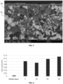
- Fig. 3 shows the scanning electron microscopy (SEM) -image of the cross-section of the porous electrode obtained from slurry No. 8, showing a matrix of the PSU polymeric binder 10 comprising the nickel particles 11.
- VSA volumetric surface area
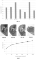
- Fig. 4 shows the VSA results, from which it is clear that all porous electrodes of the invention that were tested (i.e. from slurries Nos. 7, 12, 13 and 15) have a significantly higher volumetric surface area than the nickel foam reference. It is also reported in the literature that nickel foams exhibit a volumetric surface area in the range of 0.001-0.008 m 2 /cm 3 .
- the overpotential at 5 mA/cm 2 was determined for porous electrodes obtained from slurries Nos. 1, 6, 7 and 8, and for three references by means of the OCP and EIS as described hereinabove .
- the references were the nickel foam presented hereinabove, as well as a nickel mesh (400 mesh, 73 ⁇ m thickness, 30 ⁇ m pore size, available from Heanjia super metals Co., Ltd) and a nickel spring (knitted wire mesh, nickel 2.4066 wire diameter 0.16mm twice, from Rhodius GmbH i. Ins).
- the results are presented in Fig.
- the overpotential values of the porous electrodes of the invention are significantly lower than those of the reference electrodes, with the lowest value obtained when the particles are a mixture of nanoparticles and microparticles (slurry No. 9).
- An H-cell water electrolyser was used to evaluate the electrochemical surface area (ECSA) and activity of the several of the porous electrodes.
- ECSA electrochemical surface area
- an H-cell was built using a 1 M KOH solution as both catholyte and anolyte and a Fumasep ® FBM single-film bipolar membrane as a separator.
- An Ag/AgCI reference electrode or RHE electrode was inserted close to the working electrode.
- a metallic Ni filter with an area of about 3 cm 2 was used as the counting electrode.
- the working electrode was clamped by a stainless-steel electrode holder with an area of approximately 1.5 cm 2 immersed in the electrolyte.
- OCP Open-circuit potential
- EIS electrochemical impedance spectroscopy
- the potential range was a 0.1 V window centered on the OCP of the system to measure the non-Faradaic current response in the CV measurement.
- CV measurements were performed in static solution by sweeping the potential across this region from the more positive to the negative potential and back at 8 different scan rates: 5, 10, 25, 50, 100, 200, 400 and 800 mV/s. Scanning started after a 10-second waiting period and was repeated at least 10 times until the CV curve was stable. In this region, all current is assumed to be due to double-layer charging and the double-layer capacitance C can be measured from the charging current density I divided by the scanning rates.
- the electrochemical surface area (ECSA) of the electrode is calculated from the double-layer capacitance C divided by the specific capacitance of the sample or the capacitance of an atomically smooth planar surface of the material per unit area under identical electrolyte conditions.
- the impact of the size of the nickel particles on the ECSA value is analysed by comparing the porous electrodes obtained from slurries Nos. 7 (micro, thickness 100 ⁇ m), 12 (micro + nano, thickness 210 ⁇ m) and 14 (nano, thickness 210 ⁇ m), all having the same weight of particles, PSU, NMP and PVP. It is clear that the best result is obtained for porous electrodes comprising nickel particles having a bimodal particle size distribution, i.e. comprising both fine and coarser particles ("micro+nano").
- the ECSA value for the porous electrode obtained with only nanoparticles is significantly lower than for the porous electrode obtained with only microparticles. It is believed that when only nanoparticles are used, a larger amount (weight) of particles is required to obtain a sufficient electrical connection between the particles.
- the impact of the thickness of the porous electrodes is analysed by comparing porous electrodes obtained from slurries Nos. 5 (thickness 160 ⁇ m) and 6 (thickness 500 ⁇ m), as well as from slurries 9 (thickness 260 ⁇ m) and 13 (thickness 120 ⁇ m), wherein the slurries Nos. 9 and 13 comprise a higher weight of nickel particles and a lower amount of PSU and solvent than the slurries Nos. 5 and 6. It is clear that a higher thickness leads to a higher ECSA value.
Landscapes
- Chemical & Material Sciences (AREA)
- Chemical Kinetics & Catalysis (AREA)
- Electrochemistry (AREA)
- Engineering & Computer Science (AREA)
- Materials Engineering (AREA)
- Metallurgy (AREA)
- Organic Chemistry (AREA)
- General Chemical & Material Sciences (AREA)
- Inorganic Chemistry (AREA)
- Battery Electrode And Active Subsutance (AREA)
Priority Applications (2)
| Application Number | Priority Date | Filing Date | Title |
|---|---|---|---|
| EP23216901.1A EP4570951A1 (fr) | 2023-12-14 | 2023-12-14 | Procédé de fabrication d'une électrode poreuse |
| PCT/EP2024/085111 WO2025125113A1 (fr) | 2023-12-14 | 2024-12-06 | Procédé de production d'une électrode composite poreuse |
Applications Claiming Priority (1)
| Application Number | Priority Date | Filing Date | Title |
|---|---|---|---|
| EP23216901.1A EP4570951A1 (fr) | 2023-12-14 | 2023-12-14 | Procédé de fabrication d'une électrode poreuse |
Publications (1)
| Publication Number | Publication Date |
|---|---|
| EP4570951A1 true EP4570951A1 (fr) | 2025-06-18 |
Family
ID=89223095
Family Applications (1)
| Application Number | Title | Priority Date | Filing Date |
|---|---|---|---|
| EP23216901.1A Pending EP4570951A1 (fr) | 2023-12-14 | 2023-12-14 | Procédé de fabrication d'une électrode poreuse |
Country Status (2)
| Country | Link |
|---|---|
| EP (1) | EP4570951A1 (fr) |
| WO (1) | WO2025125113A1 (fr) |
Citations (6)
| Publication number | Priority date | Publication date | Assignee | Title |
|---|---|---|---|---|
| WO1999045604A1 (fr) | 1998-03-04 | 1999-09-10 | Valence Technology, Inc. | Procedes d'obtention d'elements electrochimiques a l'aide de techniques d'extraction de solvants |
| KR100798429B1 (ko) * | 2007-08-09 | 2008-01-28 | 공주대학교 산학협력단 | 고비표면적의 다공성 전극의 제조 방법 |
| WO2012001061A1 (fr) | 2010-06-29 | 2012-01-05 | Vito Nv | Électrode de diffusion de gaz, son procédé de fabrication, ensemble d'électrode à membrane comprenant ladite électrode et son procédé de production |
| WO2014020151A1 (fr) | 2012-08-03 | 2014-02-06 | Centre National De La Recherche Scientifique | Electrodes composites pour l'electrolyse de l'eau |
| US20170373284A1 (en) * | 2016-06-23 | 2017-12-28 | Government Of The United States As Represented By The Secretary Of The Air Force | Bendable, creasable, and printable batteries with enhanced safety and high temperture stability - methods of fabrication, and methods of using the same |
| JP7230640B2 (ja) * | 2019-03-28 | 2023-03-01 | 三菱マテリアル株式会社 | 多孔質体電極およびそれを備えた水電解セル |
-
2023
- 2023-12-14 EP EP23216901.1A patent/EP4570951A1/fr active Pending
-
2024
- 2024-12-06 WO PCT/EP2024/085111 patent/WO2025125113A1/fr active Pending
Patent Citations (6)
| Publication number | Priority date | Publication date | Assignee | Title |
|---|---|---|---|---|
| WO1999045604A1 (fr) | 1998-03-04 | 1999-09-10 | Valence Technology, Inc. | Procedes d'obtention d'elements electrochimiques a l'aide de techniques d'extraction de solvants |
| KR100798429B1 (ko) * | 2007-08-09 | 2008-01-28 | 공주대학교 산학협력단 | 고비표면적의 다공성 전극의 제조 방법 |
| WO2012001061A1 (fr) | 2010-06-29 | 2012-01-05 | Vito Nv | Électrode de diffusion de gaz, son procédé de fabrication, ensemble d'électrode à membrane comprenant ladite électrode et son procédé de production |
| WO2014020151A1 (fr) | 2012-08-03 | 2014-02-06 | Centre National De La Recherche Scientifique | Electrodes composites pour l'electrolyse de l'eau |
| US20170373284A1 (en) * | 2016-06-23 | 2017-12-28 | Government Of The United States As Represented By The Secretary Of The Air Force | Bendable, creasable, and printable batteries with enhanced safety and high temperture stability - methods of fabrication, and methods of using the same |
| JP7230640B2 (ja) * | 2019-03-28 | 2023-03-01 | 三菱マテリアル株式会社 | 多孔質体電極およびそれを備えた水電解セル |
Non-Patent Citations (3)
| Title |
|---|
| HARKS PETER-PAUL R M L ET AL: "Immersion precipitation route towards high performance thick and flexible electrodes for Li-ion batteries", JOURNAL OF POWER SOURCES, ELSEVIER, AMSTERDAM, NL, vol. 441, 17 October 2019 (2019-10-17), XP085864457, ISSN: 0378-7753, [retrieved on 20191017], DOI: 10.1016/J.JPOWSOUR.2019.227200 * |
| N. PLANKENSTEINERR. RUPP ET AL., MATERIALS TODAY ENERGY, vol. 30, 2022, pages 101172 |
| RUIGEN DINGSHENGSHENG CUI ET AL., CATALYST SCIENCE & TECHNOLOGY, 2017 |
Also Published As
| Publication number | Publication date |
|---|---|
| WO2025125113A1 (fr) | 2025-06-19 |
Similar Documents
| Publication | Publication Date | Title |
|---|---|---|
| Xu et al. | Recent advances in hybrid sodium–air batteries | |
| US9105907B2 (en) | Material for an electrochemical device | |
| CN110023542B (zh) | 碱水电解用复极式电解槽以及氢制造方法 | |
| EP3933069A1 (fr) | Séparateur pour l'électrolyse de l'eau alcaline | |
| EP2827412A1 (fr) | Microtubes constitués de nanotubes de carbone | |
| EP3919654A1 (fr) | Diaphragme d'électrolyse d'eau alcaline avec électrode, son procédé de production et dispositif d'électrolyse de l'eau | |
| US9988727B2 (en) | Composite electrodes for the electrolysis of water | |
| US20230047140A1 (en) | Electrodes comprising liquid/gas diffusion layers and systems and methods for making and using the same | |
| CN112144076A (zh) | 一体化膜电极及其制备方法和应用 | |
| WO2023280760A1 (fr) | Séparateur pour l'électrolyse alcaline d'eau | |
| EP4367290A1 (fr) | Séparateur pour électrolyse d'une solution aqueuse alcaline | |
| KR20230150210A (ko) | 분리막 및 이를 포함하는 전기화학 전환 셀 | |
| JP2025514058A (ja) | セパレータおよびこれを含む電気化学転換セル | |
| EP4367289A1 (fr) | Séparateur pour électrolyse d'une solution aqueuse alcaline | |
| EP4570951A1 (fr) | Procédé de fabrication d'une électrode poreuse | |
| EP4570952A1 (fr) | Procédé de préparation d'électrodes poreuses métalliques à haute performance | |
| Abdel-Karim | Nanoporous metallic foams for energy applications: electrochemical approaches for synthesizing and characterization | |
| US20250023059A1 (en) | Electrodes comprising liquid/gas diffusion layers and systems and methods for making and using the same | |
| US20240068116A1 (en) | Microporous asymmetric organic/inorganic composite membrane | |
| WO2025248230A1 (fr) | Assemblage membrane-électrodes pour électrolyseur d'eau | |
| CN120359259A (zh) | 用于电解的阴离子交换聚合物和膜 |
Legal Events
| Date | Code | Title | Description |
|---|---|---|---|
| PUAI | Public reference made under article 153(3) epc to a published international application that has entered the european phase |
Free format text: ORIGINAL CODE: 0009012 |
|
| STAA | Information on the status of an ep patent application or granted ep patent |
Free format text: STATUS: THE APPLICATION HAS BEEN PUBLISHED |
|
| AK | Designated contracting states |
Kind code of ref document: A1 Designated state(s): AL AT BE BG CH CY CZ DE DK EE ES FI FR GB GR HR HU IE IS IT LI LT LU LV MC ME MK MT NL NO PL PT RO RS SE SI SK SM TR |
|
| STAA | Information on the status of an ep patent application or granted ep patent |
Free format text: STATUS: THE APPLICATION IS DEEMED TO BE WITHDRAWN |