EP4571017A1 - Adaptateur de pied de mât pour mâts de caténaires - Google Patents
Adaptateur de pied de mât pour mâts de caténaires Download PDFInfo
- Publication number
- EP4571017A1 EP4571017A1 EP24218151.9A EP24218151A EP4571017A1 EP 4571017 A1 EP4571017 A1 EP 4571017A1 EP 24218151 A EP24218151 A EP 24218151A EP 4571017 A1 EP4571017 A1 EP 4571017A1
- Authority
- EP
- European Patent Office
- Prior art keywords
- mast
- adapter
- fastening
- overhead line
- support surface
- Prior art date
- Legal status (The legal status is an assumption and is not a legal conclusion. Google has not performed a legal analysis and makes no representation as to the accuracy of the status listed.)
- Pending
Links
Images

Classifications
-
- E—FIXED CONSTRUCTIONS
- E04—BUILDING
- E04H—BUILDINGS OR LIKE STRUCTURES FOR PARTICULAR PURPOSES; SWIMMING OR SPLASH BATHS OR POOLS; MASTS; FENCING; TENTS OR CANOPIES, IN GENERAL
- E04H12/00—Towers; Masts or poles; Chimney stacks; Water-towers; Methods of erecting such structures
- E04H12/34—Arrangements for erecting or lowering towers, masts, poles, chimney stacks, or the like
- E04H12/347—Arrangements for setting poles in the ground
-
- E—FIXED CONSTRUCTIONS
- E02—HYDRAULIC ENGINEERING; FOUNDATIONS; SOIL SHIFTING
- E02D—FOUNDATIONS; EXCAVATIONS; EMBANKMENTS; UNDERGROUND OR UNDERWATER STRUCTURES
- E02D27/00—Foundations as substructures
- E02D27/32—Foundations for special purposes
- E02D27/42—Foundations for poles, masts or chimneys
-
- E—FIXED CONSTRUCTIONS
- E02—HYDRAULIC ENGINEERING; FOUNDATIONS; SOIL SHIFTING
- E02D—FOUNDATIONS; EXCAVATIONS; EMBANKMENTS; UNDERGROUND OR UNDERWATER STRUCTURES
- E02D27/00—Foundations as substructures
- E02D27/32—Foundations for special purposes
- E02D27/42—Foundations for poles, masts or chimneys
- E02D27/425—Foundations for poles, masts or chimneys specially adapted for wind motors masts
-
- E—FIXED CONSTRUCTIONS
- E04—BUILDING
- E04H—BUILDINGS OR LIKE STRUCTURES FOR PARTICULAR PURPOSES; SWIMMING OR SPLASH BATHS OR POOLS; MASTS; FENCING; TENTS OR CANOPIES, IN GENERAL
- E04H12/00—Towers; Masts or poles; Chimney stacks; Water-towers; Methods of erecting such structures
- E04H12/22—Sockets or holders for poles or posts
- E04H12/2207—Sockets or holders for poles or posts not used
- E04H12/2215—Sockets or holders for poles or posts not used driven into the ground
-
- E—FIXED CONSTRUCTIONS
- E04—BUILDING
- E04H—BUILDINGS OR LIKE STRUCTURES FOR PARTICULAR PURPOSES; SWIMMING OR SPLASH BATHS OR POOLS; MASTS; FENCING; TENTS OR CANOPIES, IN GENERAL
- E04H12/00—Towers; Masts or poles; Chimney stacks; Water-towers; Methods of erecting such structures
- E04H12/22—Sockets or holders for poles or posts
- E04H12/2253—Mounting poles or posts to the holder
- E04H12/2261—Mounting poles or posts to the holder on a flat base
-
- E—FIXED CONSTRUCTIONS
- E04—BUILDING
- E04H—BUILDINGS OR LIKE STRUCTURES FOR PARTICULAR PURPOSES; SWIMMING OR SPLASH BATHS OR POOLS; MASTS; FENCING; TENTS OR CANOPIES, IN GENERAL
- E04H12/00—Towers; Masts or poles; Chimney stacks; Water-towers; Methods of erecting such structures
- E04H12/22—Sockets or holders for poles or posts
- E04H12/2284—Means for adjusting the orientation of the post or pole
-
- E—FIXED CONSTRUCTIONS
- E04—BUILDING
- E04H—BUILDINGS OR LIKE STRUCTURES FOR PARTICULAR PURPOSES; SWIMMING OR SPLASH BATHS OR POOLS; MASTS; FENCING; TENTS OR CANOPIES, IN GENERAL
- E04H12/00—Towers; Masts or poles; Chimney stacks; Water-towers; Methods of erecting such structures
- E04H12/22—Sockets or holders for poles or posts
- E04H12/2253—Mounting poles or posts to the holder
- E04H12/2276—Clamping poles or posts on a stub
Definitions
- the invention relates to a use of a mast base adapter and a method for erecting an overhead line mast.
- Signal masts are generally smaller than overhead line masts. Signal masts carry signals important for railway operations or the necessary devices.
- Overhead line masts are used to mount overhead lines, from which a train can draw power. Overhead line masts must be more stable, among other things, because the power lines can be exposed to wind and because the entire overhead line system is heavy.
- So-called foundations are used to secure the masts, which form the connection between the ground and the mast.
- concrete foundations are used. These are formed by driving a pile into the ground next to a railway line and digging a pit, which is then filled with concrete to form the head of the previously installed pile. A mast is then inserted into the uncured concrete and aligned. Once the concrete has hardened, the mast is also connected to the ground. These days, threaded bolts are usually inserted into the concrete to which the mast is attached, with only the bolts protruding from the concrete. The connection between the mast and the foundation can be easily removed to allow for the trouble-free removal of a damaged mast or one requiring maintenance.
- driven pipe foundations are increasingly being used.
- a driven pipe also known as a driven pile, is driven into the ground.
- An adapter is then attached to the upper end of the driven pipe, to which the mast is attached.
- a corresponding mast base adapter is available, for example, from the DE 20 2004 015 733 U1
- This mast base adapter consists of a sleeve and a head plate connected to the sleeve.
- the sleeve serves to connect to the piling pipe, and the head plate provides means for attaching a signal mast.
- the signal mast can be attached to the head plate.
- the object of the present invention is to provide a foundation for overhead lines that can be manufactured using simple means.
- the use according to the invention relates to a mast base adapter comprising a fastening tube and an adapter plate.
- the fastening tube is designed to be fastened to a ramming pipe inserted into the ground.
- the adapter plate has a first and a second support surface, which lie opposite one another and are preferably flat and parallel.
- the first support surface is welded to the end of the fastening tube, wherein the fastening tube is preferably cylindrical and aligned with the first support surface such that a fastening tube axis and the first support surface are arranged at right angles.
- the second support surface has means for fastening an overhead line mast and has a length of at least 680 mm along a first side.
- the basic structure of the mast base adapter largely corresponds to the structure of mast base adapters as they are known from the DE 20 2004 015 733 U1
- the mast base adapter according to the invention has a particularly large side length of the support surface of the second adapter plate of at least 680 mm.
- the second support surface is designed to support a base plate of a overhead line mast, for which purpose it is flat and level in a preferred embodiment.
- mast base adapters Due to the forces acting on overhead line masts, the use of mast base adapters in conjunction with pile-driving pipes for the foundation of overhead line masts has not been considered until now. However, by designing mast base adapters with a large adapter plate, the invention makes it possible to use mast base adapters for the foundation of overhead line masts as well.
- the advantage of using a mast base adapter for the foundation of an overhead line mast in conjunction with a pile-driving pipe is that such a foundation can be constructed on site using simple means.
- the mast base adapter simply needs to be placed on the upper part of a pile-driving pipe and secured to it.
- the overhead line mast can then be easily placed on the mast base adapter and secured to it using the fasteners.
- the use according to the invention thus provides the advantage of a pile-driving pipe foundation with a mast base adapter for overhead line masts.
- Another embodiment of the use relates to an adapter plate that has a length of at least 540 mm along a second side of the second support surface.
- the first and second adapter plates are rectangular and parallel.
- both support surfaces are oriented to each other such that they overlap when viewed from above on one of the adapter plates.
- Such an adapter plate is particularly easy to manufacture because it It simply needs to be cut out of a suitably large sheet metal. Furthermore, it can be easily connected to a corresponding base plate of the overhead line mast.
- the mounting tube has a mounting tube diameter of at least 400 mm, preferably at least 406 mm or 457 mm, and a mounting tube length of at least 490 mm, preferably at least 530 mm. These dimensions are sufficiently large to allow the mast base adapter to be connected to ramming tubes that are large enough to absorb the forces typical of overhead line masts.
- the fastening elements are through-holes or threaded bolts protruding from the second support surface of the adapter plate.
- screws inserted through the through-holes and secured with a nut, or nuts screwed onto the protruding threaded bolts are used to create a connection between the base plate of the overhead line mast and the mast base adapter.
- the through-hole it extends from the second to the first support surface.
- Another design provides four fastening elements. With relatively low manufacturing effort, four fastening elements allow for uniform and sufficient force transmission between the mast base adapter and the overhead line mast.
- the four fastening elements are arranged in a rectangle.
- the rectangle has two rectangular sides, the first of which is at least 400 mm long and the second of which is is at least 500 mm.
- the rectangle side lengths are 500 mm and 400 mm or 650 mm and 450 mm.
- struts are welded to the first support side and to the mounting tube.
- the method according to the invention for establishing the foundation of an overhead line mast comprises, in a first step, providing an overhead line mast with a base plate, a driving pipe, and a mast base adapter.
- the mast base adapter comprises a fastening pipe and an adapter plate, wherein the fastening pipe is designed to be fastened to a driving pipe.
- the adapter plate has a first support surface to which the fastening pipe is welded, and a second support surface opposite the first.
- the first support surface has fastening means for fastening the overhead line mast and has a length of at least 680 mm along a first side.
- the driving pipe is inserted into the ground.
- the mast base adapter is applied to the driving pipe.
- the mast base adapter is aligned.
- the mast base adapter is fastened to the driving pipe. Preferably, screws are used for this purpose, which are inserted through through holes in the fastening pipe and driving pipe and secured with nuts.
- the overhead line mast is mounted on the mast base adapter by positioning the base plate on the adapter plate.
- the overhead line mast is aligned relative to the mast base adapter. A gap between the overhead line mast and the mast base adapter is filled with mortar. This preferably aligns the overhead line mast so that it is perpendicular to the ground.
- the base plate of the overhead line mast is attached to the fasteners of the mast base adapter, thus securing the overhead line mast to the mast base adapter.
- the method according to the invention makes it possible to provide a secure foundation for an overhead line mast using simple means. It should be noted that inserting the pile-driving pipe into the ground is relatively simple compared to creating a concrete-filled pit. The same applies to the installation of the mast base adapter.
- the mast base adapter according to the invention has a longer first side of the second, upper support surface than conventional mast base adapters, thus providing a sufficiently large support surface for a base plate of an overhead line mast, enabling it to absorb the high forces that occur in an overhead line mast.
- the decisive factor in the method according to the invention for erecting an overhead line mast is that, on the one hand, the overhead line mast can be mounted sufficiently firmly using simple means so that the corresponding forces occurring during operation can be transmitted, and on the other hand, that it can also be correctly aligned. Without correct alignment, increased stress during operation is to be expected, which impairs long-term durability. Incorrect alignment can also result in a power line attached to the overhead line mast being at the incorrect distance from a track below. This could result in a train not collecting current correctly.
- metal sheets are used to align masts on mast base adapters; these sheets are placed between the mast base adapter and the base plate of the overhead line mast.
- the invention uses mortar to align the overhead line mast. While the mortar hardens, correct alignment can be achieved using simple means. Once the mortar has hardened in the space between the base plate of the overhead line mast and the adapter plate, both correct alignment of the overhead line mast and sufficient force transmission are guaranteed.
- Fig. 1 shows a perspective view of a mast base adapter 1.
- the mast base adapter 1 has a cylindrical mounting tube 2 and an adapter plate 3.
- the adapter plate 3 is welded to one end of the mounting tube 2, with the adapter plate 3 being placed on the mounting tube 2 with a first support surface.
- the adapter plate 3 has a rectangular shape. It is aligned on the mounting tube such that the center of the rectangle lies on the center line of the mounting tube 2.
- the second support surface of the adapter plate 3, which faces away from the mounting tube 2, has four through-holes 4.
- the through-holes 4 are located near the corners of the rectangle.
- a catenary mast can be attached to them.
- the catenary mast has a base plate, which also has holes that follow the same pattern as the through-holes. After the catenary mast has been aligned accordingly, screws are inserted from below through the holes in the base plate and the adapter plate and secured with nuts, thus attaching the catenary mast to the mast base adapter.
- Fig. 2 shows a mast base adapter 5.
- the mast base adapter 5 is constructed similarly to the mast base adapter 1. However, the mast base adapter 5 does not have through-holes. Instead, it has four threaded bolts 6 arranged in the corners of the rectangle. To attach a catenary mast to the mast base adapter 5, the threaded bolts 6 are inserted through corresponding holes in the base plate of the catenary mast. Nuts can then be applied from above, and after tightening, a connection is achieved between the mast base adapter and the catenary mast.
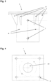
- Fig. 3 shows the mast base adapter 1 from a side view. It can be seen that the fastening tube 2 has through holes 7. After the fastening tube 2 has been pushed onto a ramming tube, the through holes 7 allow the mast base adapter 1 to be fastened to the ramming tube. For this purpose, a screw is pushed through the through holes 7 and a corresponding through hole in the ramming tube and then secured with a nut.
- the threaded holes 8 are used to align the mast base adapter 1 on the ramming tube. Grub screws can be screwed through them to align the mast base adapter 1 before the annular gap between the ramming tube and the fastening tube 2 is filled with grout.
- struts 9 can be seen, which support the adapter plate 3 against the fastening tube 2.
- the struts 9 have a triangular shape, with one side of the triangle being connected to the first support surface of the adapter plate 3 and another side of the triangle being connected to the outer surface of the fastening tube 2.
- Fig. 4 shows the mast base adapter 1 from a top view.
- the through holes 4 are located near the corners of the rectangular adapter plate 3.
- the adapter plate 3 has a central through hole 10.
- the diameter of the through hole 10 is smaller than the diameter of the mounting tube 2.
- the through hole 10 serves to allow nuts to be passed through it, which can then be screwed onto screws that pass through the Through hole 7 and the corresponding hole of the ramming pipe were inserted.
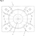
- Fig. 5 shows the mast base adapter 1 from a bottom view. It can be seen that the struts 9 are distributed in pairs of two around the circumference of the mounting tube 2. The angular spacing between the pairs is larger than that between the struts 9 belonging to a respective pair. Each pair is aligned toward one of the through-holes 4. Furthermore, it is clearly visible that the centrally located through-hole 10 is smaller than the diameter of the mounting tube 2.
Landscapes
- Engineering & Computer Science (AREA)
- Architecture (AREA)
- Civil Engineering (AREA)
- Structural Engineering (AREA)
- Life Sciences & Earth Sciences (AREA)
- General Life Sciences & Earth Sciences (AREA)
- Mining & Mineral Resources (AREA)
- Paleontology (AREA)
- General Engineering & Computer Science (AREA)
- Foundations (AREA)
Applications Claiming Priority (1)
| Application Number | Priority Date | Filing Date | Title |
|---|---|---|---|
| DE102023134215.0A DE102023134215A1 (de) | 2023-12-06 | 2023-12-06 | Mastfußadapter für Oberleitungsmasten |
Publications (1)
| Publication Number | Publication Date |
|---|---|
| EP4571017A1 true EP4571017A1 (fr) | 2025-06-18 |
Family
ID=93841874
Family Applications (1)
| Application Number | Title | Priority Date | Filing Date |
|---|---|---|---|
| EP24218151.9A Pending EP4571017A1 (fr) | 2023-12-06 | 2024-12-06 | Adaptateur de pied de mât pour mâts de caténaires |
Country Status (2)
| Country | Link |
|---|---|
| EP (1) | EP4571017A1 (fr) |
| DE (1) | DE102023134215A1 (fr) |
Citations (3)
| Publication number | Priority date | Publication date | Assignee | Title |
|---|---|---|---|---|
| DE202004015733U1 (de) | 2004-10-02 | 2004-12-23 | BBL Bahnbau Lüneburg GmbH | Vorrichtung zur Gründung von Signalmasten |
| WO2022229481A1 (fr) * | 2021-04-30 | 2022-11-03 | Road Steel Engineering, S.L. | Dispositif de liaison pour poteau de structure de support de l'équipement de voies de circulation, et structure de support de l'équipement de voies de circulation comprenant ledit dispositif de liaison |
| EP3613926B1 (fr) * | 2018-08-22 | 2023-04-26 | European Trans Energy GmbH | Mât en acier |
-
2023
- 2023-12-06 DE DE102023134215.0A patent/DE102023134215A1/de active Pending
-
2024
- 2024-12-06 EP EP24218151.9A patent/EP4571017A1/fr active Pending
Patent Citations (3)
| Publication number | Priority date | Publication date | Assignee | Title |
|---|---|---|---|---|
| DE202004015733U1 (de) | 2004-10-02 | 2004-12-23 | BBL Bahnbau Lüneburg GmbH | Vorrichtung zur Gründung von Signalmasten |
| EP3613926B1 (fr) * | 2018-08-22 | 2023-04-26 | European Trans Energy GmbH | Mât en acier |
| WO2022229481A1 (fr) * | 2021-04-30 | 2022-11-03 | Road Steel Engineering, S.L. | Dispositif de liaison pour poteau de structure de support de l'équipement de voies de circulation, et structure de support de l'équipement de voies de circulation comprenant ledit dispositif de liaison |
Also Published As
| Publication number | Publication date |
|---|---|
| DE102023134215A1 (de) | 2025-06-12 |
Similar Documents
| Publication | Publication Date | Title |
|---|---|---|
| EP1735533B2 (fr) | Procede permettant d'eriger une tour aussi bien que une eolienne | |
| EP1735506B1 (fr) | Procede permettant d'eriger une tour | |
| EP3004467B1 (fr) | Fondation en béton et procédé de fabrication d'une fondation en béton pour une tour d'éolienne ainsi que dispositif de positionnement de gaines dans une fondation en béton | |
| EP2744955A2 (fr) | Procédé et dispositif permettant la transition entre une partie de tour en acier et une partie de tour en béton précontraint | |
| DE102019007619B4 (de) | Verankerung mit Verankerungsvorrichtung und Verfahren zur Herstellung der Verankerung | |
| DE102016217793A1 (de) | Vorrichtung zur Verbindung einer Rammpfahlgründung mit einem Tragwerk und Verfahren zum Herstellen einer solchen Verbindung | |
| EP2159354A1 (fr) | Dispositif de fixation de poteaux pour parois de protection | |
| EP1870534A2 (fr) | Structure de raidissement, élément de fixation et procédé destiné au raidissement du cadre de support d'un coffrage de plafond | |
| DE102023134215A1 (de) | Mastfußadapter für Oberleitungsmasten | |
| DE202023107239U1 (de) | Mastfußadapter für Oberleitungsmasten | |
| EP1927698A2 (fr) | Dispositif de fixation pour mâts de signalisation | |
| DE102009024889A1 (de) | Bohrfundament mit zylindrischem Grundkörper | |
| DE4435489C2 (de) | Verfahren und Vorrichtung zum Auswechseln eines Hauptdiagonalstabes | |
| EP3760476B1 (fr) | Dispositif de fixation, en particulier d'un bras en forme de tige à un mât, agencement doté d'un dispositif et procédé de fabrication d'un tel agencement | |
| EP2430245A2 (fr) | Cage de fondation, fondation et procédé de création d'une fondation | |
| DE202023103836U1 (de) | Positioniervorrichtung | |
| EP4248017B1 (fr) | Fondation pour tour d'une station de transmission ou pour la construction d'une ligne aérienne | |
| EP3078778A1 (fr) | Fondation pour eolienne | |
| DE102024107581B4 (de) | Vorrichtung und Verfahren zur Tiefengründung von Fundamenten für Lärm- und Sichtschutzbauten | |
| AT520550B1 (de) | Adaptervorrichtung für einen Rammpfahl | |
| DE4435488A1 (de) | Verfahren und Vorrichtung zum Auswechseln eines Knotenbleches | |
| DE102023005363A1 (de) | Tragbauteil mit Gründungsrohr für einen Strommast und Verfahren zum Einbringen des Gründungsrohres | |
| DE202022100086U1 (de) | Befestigungsvorrichtung für Signal- und Beleuchtungsmasten für den Schienenverkehr | |
| DE102021212813A1 (de) | Stütz- oder Tragvorrichtung | |
| EP4589076A1 (fr) | Dispositif pour armer de manière récupérable des suspensions à terre armée |
Legal Events
| Date | Code | Title | Description |
|---|---|---|---|
| PUAI | Public reference made under article 153(3) epc to a published international application that has entered the european phase |
Free format text: ORIGINAL CODE: 0009012 |
|
| STAA | Information on the status of an ep patent application or granted ep patent |
Free format text: STATUS: THE APPLICATION HAS BEEN PUBLISHED |
|
| AK | Designated contracting states |
Kind code of ref document: A1 Designated state(s): AL AT BE BG CH CY CZ DE DK EE ES FI FR GB GR HR HU IE IS IT LI LT LU LV MC ME MK MT NL NO PL PT RO RS SE SI SK SM TR |
|
| STAA | Information on the status of an ep patent application or granted ep patent |
Free format text: STATUS: REQUEST FOR EXAMINATION WAS MADE |
|
| 17P | Request for examination filed |
Effective date: 20251215 |