EP4571020A1 - Serrure à pêne pivotant - Google Patents
Serrure à pêne pivotant Download PDFInfo
- Publication number
- EP4571020A1 EP4571020A1 EP24216722.9A EP24216722A EP4571020A1 EP 4571020 A1 EP4571020 A1 EP 4571020A1 EP 24216722 A EP24216722 A EP 24216722A EP 4571020 A1 EP4571020 A1 EP 4571020A1
- Authority
- EP
- European Patent Office
- Prior art keywords
- bolt
- edge
- housing
- lock
- locking
- Prior art date
- Legal status (The legal status is an assumption and is not a legal conclusion. Google has not performed a legal analysis and makes no representation as to the accuracy of the status listed.)
- Pending
Links
Images


Classifications
-
- E—FIXED CONSTRUCTIONS
- E05—LOCKS; KEYS; WINDOW OR DOOR FITTINGS; SAFES
- E05C—BOLTS OR FASTENING DEVICES FOR WINGS, SPECIALLY FOR DOORS OR WINDOWS
- E05C9/00—Arrangements of simultaneously actuated bolts or other securing devices at well-separated positions on the same wing
- E05C9/18—Details of fastening means or of fixed retaining means for the ends of bars
- E05C9/1825—Fastening means
- E05C9/1833—Fastening means performing sliding movements
- E05C9/1841—Fastening means performing sliding movements perpendicular to actuating bar
-
- E—FIXED CONSTRUCTIONS
- E05—LOCKS; KEYS; WINDOW OR DOOR FITTINGS; SAFES
- E05B—LOCKS; ACCESSORIES THEREFOR; HANDCUFFS
- E05B17/00—Accessories in connection with locks
- E05B17/20—Means independent of the locking mechanism for preventing unauthorised opening, e.g. for securing the bolt in the fastening position
- E05B17/2007—Securing, deadlocking or "dogging" the bolt in the fastening position
- E05B17/2015—Securing, deadlocking or "dogging" the bolt in the fastening position with wedging action
-
- E—FIXED CONSTRUCTIONS
- E05—LOCKS; KEYS; WINDOW OR DOOR FITTINGS; SAFES
- E05C—BOLTS OR FASTENING DEVICES FOR WINGS, SPECIALLY FOR DOORS OR WINDOWS
- E05C9/00—Arrangements of simultaneously actuated bolts or other securing devices at well-separated positions on the same wing
- E05C9/18—Details of fastening means or of fixed retaining means for the ends of bars
- E05C9/1825—Fastening means
- E05C9/1875—Fastening means performing pivoting movements
Definitions
- the invention relates to a lock for a door or window with a pivot bolt. Such locks are already known.
- Swing bolts are considered particularly secure locking devices because they engage behind a locking edge of the bolt engagement, thus safely absorbing the horizontal displacement forces exerted on the sash during a break-in attempt.
- an attempt is made to force the bolt engagements out of their locking engagement with the bolt by deforming the sash or the sash stile perpendicular to the rebate using a tool.
- the sometimes hook-shaped swing bolts prevent this and do not allow the distance between the rebates to increase.
- the sash can then be vertically loaded using similar means to cause the swing bolt to strike the bolt engagement and swing back.
- a direct attack on the swing bolt with the aim of swinging it back into its unlocked position is also possible. This pushing back is often done with brute force.
- Various options have already been considered to prevent these attacks from being successful.
- the DE 10341442 A1 discloses a lock with a pivot bolt that pivots forward from a lock housing in its locked position under the influence of a spring.
- the pivot bolt is pivoted back into the lock housing via a drive rod slide.
- a blocking element is provided in the lock housing, which supports the pivot bolt in its locked position to prevent it from pivoting back.
- the swivel bolt is first raised and the locking projection is moved past the longitudinal end of the opening.
- the first disclosed embodiment requires an auxiliary slide to move the swivel bolt.
- the second embodiment provides a lever linkage that lowers the swivel bolt. Therefore, both solutions provide several moving components, which requires complex assembly.
- a swing bolt drive has become known in which the control cam in the connecting rod slide of a secondary lock is L-shaped, and a control pin of the swing bolt, in the locked position, engages a leg of the control cam running parallel to the direction of travel of the connecting rod. This prevents the swing bolt from being pushed back. This leg is designed to be short so as not to reduce the available stroke of the connecting rod.
- the EP 0578004 A2 discloses a push-back lock, which is to be activated by the engagement of a control pin.
- the control pin is guided in a slotted guide in the lock cover and the lock base and is carried along this guide by the drive rod.
- the control pin engages both in the slotted guide and in a drive recess running perpendicular to the faceplate and the direction of movement of the drive rod.
- the slotted guide is designed in such a way that it forms a slotted guide at an obtuse angle to the drive recess. running section. When the pivot bolt is pushed back, the control pin therefore blocks the pivot bolt.
- This design requires precise coordination of the cam in the lock base and the lock cover, as well as the drive rod.
- the EP 0411271 A1 shows a swing bolt lock in which the swing bolt has an S-shaped slotted guide, into which a control pin of a connecting rod slide engages.
- the slotted guide is positioned relative to the pivot axis of the swing bolt so that the pivoting movement is triggered when the slider passes through the slotted guide.
- the ends of the slotted guide run parallel to the direction of travel of the connecting rod, so that the swing bolt is fixed in the locking and locking positions.
- the locking position within the meaning of the invention is reached when the drive rod has assumed a locking end position and the locking elements driven by the drive rod assume their engagement position with the frame-side locking engagement elements.
- the object of the invention is therefore to make it more difficult to push back the bolt and to achieve a simple and secure lock against pushing back the swivel bolt.
- the invention provides a housing edge running perpendicular to the faceplate of the housing, which edge lies in the return pivoting direction of the hook mouth with respect to the pivot axis of the swivel bolt and, in the locking position, projects into the interior of the housing at a short distance from a body edge of the swivel bolt.
- the hook jaw is designed with a swivel bolt edge aligned approximately parallel to the faceplate when in the locking position. This allows the swivel bolt to be displaced toward the housing edge parallel to the faceplate when a force is applied to the bolt during a break-in.
- a further development provides for the swivel bolt to have a circular arc contour running concentrically to the pivot axis, to which a tangentially running body edge is connected.
- the circular arc contour can thus be pivoted past the housing edge to achieve the locking position.
- a particularly simple design involves attaching the housing edge to a lock cover. This simplifies production, as only the lock cover needs to be attached.
- the housing edge can be attached to a component anchored in the lock cover.
- This additional component allows for a flat design of the lock cover and a sharp-edged design of the housing edge.
- the secondary lock case 1 shown is connected to a main lock case in a known manner by means of a faceplate 2 and a drive rod 3.
- a drive rod slide 4 is provided in the secondary lock case 1 which is coupled to the drive rod 3 and can be controlled by the main lock case via a handle and/or key.
- a link follower 5 is attached to the connecting rod slide 4.
- the link follower 5 is assigned to the pivot bolt 6 and engages in a contour 7 provided on the rear side of the pivot bolt 6.
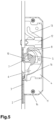
- the link follower 5 has a triangular shape and is in the open position Fig. 5 on an edge 8 running parallel to the faceplate 2. If the drive rod slide 4 is moved from the open position to Fig. 5 into the locking position Fig. 4 switched, the link follower 5 moves relative to the pivot bolt 6, which is mounted exclusively for rotation on the axis 9.
- a locking bolt 12 is slidably mounted in the housing 11 next to the pivot bolt 6.
- the locking bolt 12 engages with a pin (not visible here) in an S-shaped guide 13.
- the pivot bolt 6 and the locking bolt 12 form a locking mechanism of a secondary case 1.
- the secondary case 1 is provided in addition to the main lock case (not shown) of a locking device and forms a locking point located remote therefrom.
- the housing 11 consists of a housing case 14, which forms a shallow tray, and a lock cover 14', which essentially consists of a flat plate.
- the faceplate 2 closes the housing 11 in the direction of a rebate surface to which the locking device is mounted and forms a front closure.
- the housing case 14 and lock cover 14' are designed as stamped and bent parts.
- the pivot bolt 6 and the locking bolt 12 absorb pressure forces that arise when the leaf to which the locking device is attached is pressed against the frame to which the locking engagement elements associated with the locking device are attached.
- the locking device In addition to these forces, the locking device must also be capable of absorbing forces exerted during a break-in attempt. In addition to forces perpendicular to the plane of the drawing, these include forces generated by tools driven between the sash and frame with the aim of expanding the access space. If sufficient space is opened up by drilling in the sash and/or frame or by the aforementioned tools, an attempt is made to relocate the bolts (swing bolt 6 and locking pin 12). To do this, for example, a torque can be applied to the swing bolt 6, which in the drawings causes a counterclockwise movement.
- the link follower 5 has a small lever arm compared to a tool that engages the hook mouth 15.
- the anti-return device consists of a housing edge 16 running perpendicular to the faceplate 2 of the housing 11, which, with respect to the axis 9 of the swivel bolt 6, lies in the swing-back direction R of the hook jaw 15 and, in the locked position, protrudes into the interior of the housing 11 at a short distance 17 from a body edge 18 of the swivel bolt 6.
- the body edge 18 is an extension of a circular arc contour 19.
- the circular arc contour 19 runs concentrically to the axis 9.
- the body edge 18 adjoins the circular arc contour 19 as a tangent and extends beyond the intersection point 20 of the vertical central axis 21 with the circular arc contour 19.
- the body edge 18, slightly related to an imaginary concentric extension of the circular arc contour 19 extends beyond the radius of the circular arc contour 19.
- the distance 22 of the housing edge 16 from the axis 9 is thereby reduced in the last swivel range.
- the design does not impede the pivoting movement of the pivot bolt 6. If a force is applied to the pivot bolt 6 with the intention of pushing it back, the axis 9 shifts downward in the drawing. This causes the body edge 18 to rest on the housing edge 16. The displacement of the axis 9 need only be small. Any further backward pivoting movement is counteracted by the support. If further force is applied, the axis 9 shifts more significantly, which means that the support cannot be removed.
- the hook jaw 15 is provided with a pivot bolt edge aligned approximately parallel to the faceplate 2 in the locked position. In the locked position, this pivot bolt edge engages behind a locking edge of the locking engagement, and the parallel alignment of the pivot bolt edge allows the pivot bolt 6 to be displaced parallel to the faceplate 2. Pivoting of the pivot bolt 2 due to the locking engagement is prevented, which promotes a blunt force introduction into the housing edge.
- the hook jaw 15 is open upwards, and the pivot bolt 6 rotates clockwise in the locked position. Locking can also be performed in a similar manner in the opposite direction to the described direction.
- the illustrated embodiment provides that the housing edge 16 is attached to a lock cover 14'.
- the housing edge 16 is formed by an embossed portion 24, which deforms the lock cover 14' in sections toward the pivot bolt.
- an additional component to be mounted can also be provided.
Landscapes
- Engineering & Computer Science (AREA)
- Mechanical Engineering (AREA)
- Hinges (AREA)
- Lock And Its Accessories (AREA)
Applications Claiming Priority (1)
| Application Number | Priority Date | Filing Date | Title |
|---|---|---|---|
| DE202023107341.7U DE202023107341U1 (de) | 2023-12-12 | 2023-12-12 | Schloss mit Schwenkriegel |
Publications (1)
| Publication Number | Publication Date |
|---|---|
| EP4571020A1 true EP4571020A1 (fr) | 2025-06-18 |
Family
ID=89809173
Family Applications (1)
| Application Number | Title | Priority Date | Filing Date |
|---|---|---|---|
| EP24216722.9A Pending EP4571020A1 (fr) | 2023-12-12 | 2024-12-02 | Serrure à pêne pivotant |
Country Status (2)
| Country | Link |
|---|---|
| EP (1) | EP4571020A1 (fr) |
| DE (1) | DE202023107341U1 (fr) |
Families Citing this family (1)
| Publication number | Priority date | Publication date | Assignee | Title |
|---|---|---|---|---|
| DE202024102203U1 (de) | 2024-04-30 | 2024-05-23 | Kfv Karl Fliether Gmbh & Co. Kg | Kulissenfolger |
Citations (11)
| Publication number | Priority date | Publication date | Assignee | Title |
|---|---|---|---|---|
| DE3427713A1 (de) | 1984-07-27 | 1986-02-06 | Fa. Wilhelm Karrenberg, 5620 Velbert | Mehrtourig schliessendes treibstangenschloss |
| EP0411271A1 (fr) | 1989-06-22 | 1991-02-06 | Karl Fliether GmbH & Co. KG | Serrure pour bielle motrice avec une serrure supplémentaire qui est contrôlée par une serrure centrale |
| EP0578004A2 (fr) | 1992-07-10 | 1994-01-12 | Carl Fuhr GmbH & Co. | Crémone-serrure avec pêne pivotant manoeuvré par une broche qui suit une coulisse |
| DE10341442A1 (de) | 2003-09-09 | 2005-03-31 | Aug. Winkhaus Gmbh & Co. Kg | Treibstangenschloss |
| EP1544391A2 (fr) | 2003-12-19 | 2005-06-22 | Aug. Winkhaus GmbH & Co. KG | Crémone |
| DE102005002296B3 (de) | 2005-01-17 | 2006-09-07 | Roto Frank Ag | Fenster, Tür oder dergleichen sowie Treibstangenbeschlag mit einem Verriegelungs-Schwenkelement |
| EP1199428B1 (fr) * | 2000-10-18 | 2007-07-18 | Gretsch-Unitas GmbH Baubeschläge | Crémone-serrure |
| EP1790802B1 (fr) | 2005-09-27 | 2011-05-25 | Aug. Winkhaus GmbH & Co. KG | Crémone |
| DE202018003080U1 (de) | 2018-07-03 | 2018-08-06 | Kfv Karl Fliether Gmbh & Co. Kg | Schloss mit Schwenkriegel |
| DE202018103048U1 (de) * | 2018-05-30 | 2019-09-03 | Gretsch-Unitas GmbH Baubeschläge | Schloss |
| EP3795783B1 (fr) | 2019-09-18 | 2023-08-09 | WILKA SCHLIESSTECHNIK GmbH | Fermeture secondaire pour un verrouillage à points multiples |
-
2023
- 2023-12-12 DE DE202023107341.7U patent/DE202023107341U1/de active Active
-
2024
- 2024-12-02 EP EP24216722.9A patent/EP4571020A1/fr active Pending
Patent Citations (13)
| Publication number | Priority date | Publication date | Assignee | Title |
|---|---|---|---|---|
| DE3427713A1 (de) | 1984-07-27 | 1986-02-06 | Fa. Wilhelm Karrenberg, 5620 Velbert | Mehrtourig schliessendes treibstangenschloss |
| EP0411271A1 (fr) | 1989-06-22 | 1991-02-06 | Karl Fliether GmbH & Co. KG | Serrure pour bielle motrice avec une serrure supplémentaire qui est contrôlée par une serrure centrale |
| EP0578004A2 (fr) | 1992-07-10 | 1994-01-12 | Carl Fuhr GmbH & Co. | Crémone-serrure avec pêne pivotant manoeuvré par une broche qui suit une coulisse |
| EP1199428B1 (fr) * | 2000-10-18 | 2007-07-18 | Gretsch-Unitas GmbH Baubeschläge | Crémone-serrure |
| DE10341442A1 (de) | 2003-09-09 | 2005-03-31 | Aug. Winkhaus Gmbh & Co. Kg | Treibstangenschloss |
| EP1544391A2 (fr) | 2003-12-19 | 2005-06-22 | Aug. Winkhaus GmbH & Co. KG | Crémone |
| DE102005002296B3 (de) | 2005-01-17 | 2006-09-07 | Roto Frank Ag | Fenster, Tür oder dergleichen sowie Treibstangenbeschlag mit einem Verriegelungs-Schwenkelement |
| EP1790802B1 (fr) | 2005-09-27 | 2011-05-25 | Aug. Winkhaus GmbH & Co. KG | Crémone |
| DE202018103048U1 (de) * | 2018-05-30 | 2019-09-03 | Gretsch-Unitas GmbH Baubeschläge | Schloss |
| DE202018003080U1 (de) | 2018-07-03 | 2018-08-06 | Kfv Karl Fliether Gmbh & Co. Kg | Schloss mit Schwenkriegel |
| EP3591145A1 (fr) | 2018-07-03 | 2020-01-08 | KFV Karl Fliether GmbH & Co. KG | Serrure à verrou pivotant |
| EP3722542A1 (fr) | 2018-07-03 | 2020-10-14 | KFV Karl Fliether GmbH & Co. KG | Serrure à verrou pivotant |
| EP3795783B1 (fr) | 2019-09-18 | 2023-08-09 | WILKA SCHLIESSTECHNIK GmbH | Fermeture secondaire pour un verrouillage à points multiples |
Also Published As
| Publication number | Publication date |
|---|---|
| DE202023107341U1 (de) | 2024-01-10 |
Similar Documents
| Publication | Publication Date | Title |
|---|---|---|
| DE2839070A1 (de) | Schloss, insbesondere fuer tueren von automobilen | |
| DE19631451B4 (de) | Gleitblech und elektrischer Türöffner mit einem solchen Gleitblech | |
| EP0769600A2 (fr) | Charnière de porte pour véhicule à moteur combinée constructivement avec un arrêt de porte | |
| EP4571020A1 (fr) | Serrure à pêne pivotant | |
| EP0634543A1 (fr) | Serrure à combinaison avec bouton tournant, disque à cames et un levier | |
| EP0361001B1 (fr) | Serrure à crochet | |
| EP0799957A2 (fr) | Barre anti-panique réversible pour portes de secours | |
| EP1243729A2 (fr) | Dispositif de verrouillage à tige d'actionnement pour une fenêtre, une porte ou similaire | |
| EP2843169B1 (fr) | Porte coulissante avec système de support | |
| EP3426867B1 (fr) | Serrure | |
| EP1298269B1 (fr) | Mécanisme d'actionnement, notamment serrure pour une crémone et crémone comportant un tel mécanisme d'actionnement | |
| DE10360225B3 (de) | Elektrisch betätigbarer Türöffner | |
| DE3334298C3 (de) | Verschluß für Fenster, Türen oder dergleichen | |
| DE3636236A1 (de) | Panikverschluss fuer zweifluegelige tueren | |
| DE69800295T2 (de) | Treibstangenbeschlag oder Treibstangenverschluß für Tür, Fenster oder dergl. | |
| EP3591145A1 (fr) | Serrure à verrou pivotant | |
| DE102009026452B4 (de) | Auslösehebel mit einer ein öffnendes Moment für die Drehfalle erzeugenden Kontur bei Mehrklinken-Gesperre | |
| DE69807608T2 (de) | Schliessvorrichtung, insbesondere Einsteckschloss mit einer Falle, für eine Fenstertür oder dergleichen | |
| EP0167767B1 (fr) | Dispositif de verrouillage comportant au moins un verrou et des moyens de condamnation | |
| EP4573251A1 (fr) | Dispositif de décalage permettant le décalage forcé d'un battant, en particulier d'un battant coulissant, d'une fenêtre ou d'une porte | |
| DE69807801T2 (de) | Verriegelungsvorrichtung, insbesondere Einsteckschloss für den Flügel einer Tür oder eines Fensters | |
| EP2712381B1 (fr) | Serrure de porte de véhicule automobile | |
| DE202009008450U1 (de) | Treibstangenschloss | |
| EP1024240B1 (fr) | Dispositif de verrouillage | |
| DE202024102203U1 (de) | Kulissenfolger |
Legal Events
| Date | Code | Title | Description |
|---|---|---|---|
| PUAI | Public reference made under article 153(3) epc to a published international application that has entered the european phase |
Free format text: ORIGINAL CODE: 0009012 |
|
| STAA | Information on the status of an ep patent application or granted ep patent |
Free format text: STATUS: THE APPLICATION HAS BEEN PUBLISHED |
|
| AK | Designated contracting states |
Kind code of ref document: A1 Designated state(s): AL AT BE BG CH CY CZ DE DK EE ES FI FR GB GR HR HU IE IS IT LI LT LU LV MC ME MK MT NL NO PL PT RO RS SE SI SK SM TR |
|
| STAA | Information on the status of an ep patent application or granted ep patent |
Free format text: STATUS: REQUEST FOR EXAMINATION WAS MADE |
|
| 17P | Request for examination filed |
Effective date: 20250905 |