EP4571037A1 - Installation de protection solaire dotée d'une unité de commande fixée au moteur - Google Patents
Installation de protection solaire dotée d'une unité de commande fixée au moteur Download PDFInfo
- Publication number
- EP4571037A1 EP4571037A1 EP23217263.5A EP23217263A EP4571037A1 EP 4571037 A1 EP4571037 A1 EP 4571037A1 EP 23217263 A EP23217263 A EP 23217263A EP 4571037 A1 EP4571037 A1 EP 4571037A1
- Authority
- EP
- European Patent Office
- Prior art keywords
- control unit
- drive motor
- sun protection
- protection system
- sleeve
- Prior art date
- Legal status (The legal status is an assumption and is not a legal conclusion. Google has not performed a legal analysis and makes no representation as to the accuracy of the status listed.)
- Pending
Links
Images

Classifications
-
- E—FIXED CONSTRUCTIONS
- E06—DOORS, WINDOWS, SHUTTERS, OR ROLLER BLINDS IN GENERAL; LADDERS
- E06B—FIXED OR MOVABLE CLOSURES FOR OPENINGS IN BUILDINGS, VEHICLES, FENCES OR LIKE ENCLOSURES IN GENERAL, e.g. DOORS, WINDOWS, BLINDS, GATES
- E06B9/00—Screening or protective devices for wall or similar openings, with or without operating or securing mechanisms; Closures of similar construction
- E06B9/56—Operating, guiding or securing devices or arrangements for roll-type closures; Spring drums; Tape drums; Counterweighting arrangements therefor
- E06B9/68—Operating devices or mechanisms, e.g. with electric drive
- E06B9/72—Operating devices or mechanisms, e.g. with electric drive comprising an electric motor positioned inside the roller
-
- H—ELECTRICITY
- H01—ELECTRIC ELEMENTS
- H01R—ELECTRICALLY-CONDUCTIVE CONNECTIONS; STRUCTURAL ASSOCIATIONS OF A PLURALITY OF MUTUALLY-INSULATED ELECTRICAL CONNECTING ELEMENTS; COUPLING DEVICES; CURRENT COLLECTORS
- H01R13/00—Details of coupling devices of the kinds covered by groups H01R12/70 or H01R24/00 - H01R33/00
- H01R13/62—Means for facilitating engagement or disengagement of coupling parts or for holding them in engagement
- H01R13/639—Additional means for holding or locking coupling parts together, after engagement, e.g. separate keylock, retainer strap
-
- H—ELECTRICITY
- H01—ELECTRIC ELEMENTS
- H01R—ELECTRICALLY-CONDUCTIVE CONNECTIONS; STRUCTURAL ASSOCIATIONS OF A PLURALITY OF MUTUALLY-INSULATED ELECTRICAL CONNECTING ELEMENTS; COUPLING DEVICES; CURRENT COLLECTORS
- H01R13/00—Details of coupling devices of the kinds covered by groups H01R12/70 or H01R24/00 - H01R33/00
- H01R13/64—Means for preventing incorrect coupling
- H01R13/642—Means for preventing incorrect coupling by position or shape of contact members
-
- H—ELECTRICITY
- H02—GENERATION; CONVERSION OR DISTRIBUTION OF ELECTRIC POWER
- H02K—DYNAMO-ELECTRIC MACHINES
- H02K11/00—Structural association of dynamo-electric machines with electric components or with devices for shielding, monitoring or protection
- H02K11/30—Structural association with control circuits or drive circuits
- H02K11/33—Drive circuits, e.g. power electronics
-
- E—FIXED CONSTRUCTIONS
- E06—DOORS, WINDOWS, SHUTTERS, OR ROLLER BLINDS IN GENERAL; LADDERS
- E06B—FIXED OR MOVABLE CLOSURES FOR OPENINGS IN BUILDINGS, VEHICLES, FENCES OR LIKE ENCLOSURES IN GENERAL, e.g. DOORS, WINDOWS, BLINDS, GATES
- E06B9/00—Screening or protective devices for wall or similar openings, with or without operating or securing mechanisms; Closures of similar construction
- E06B9/56—Operating, guiding or securing devices or arrangements for roll-type closures; Spring drums; Tape drums; Counterweighting arrangements therefor
- E06B9/68—Operating devices or mechanisms, e.g. with electric drive
- E06B2009/6809—Control
-
- H—ELECTRICITY
- H02—GENERATION; CONVERSION OR DISTRIBUTION OF ELECTRIC POWER
- H02K—DYNAMO-ELECTRIC MACHINES
- H02K2207/00—Specific aspects not provided for in the other groups of this subclass relating to arrangements for handling mechanical energy
- H02K2207/03—Tubular motors, i.e. rotary motors mounted inside a tube, e.g. for blinds
Definitions
- the invention relates to a sun protection system with a sun protection element which can be moved between a retracted and an extended position by means of a drive motor, wherein the sun protection system has a control unit for controlling and/or supplying current to at least the drive motor, wherein the drive motor has a motor head and an output opposite the motor head.
- a sun protection system with a fabric shaft onto which a curtain can be wound, wherein the fabric shaft is supported on lateral brackets and a drive motor which drives the fabric shaft is supported on a first bracket and projects into an inner cavity of the fabric shaft, wherein a control of the drive motor and/or further electrical consumers is provided, wherein the control is fixed to the second bracket and projects into the cavity of the fabric shaft at the end of the fabric shaft opposite the motor.
- the wiring of the control and motor is problematic with this arrangement, since a cable must be laid either through the fabric shaft or externally along a support or housing.
- a tubular electric drive is known, with a tube in which a first element with a motor and a second element consisting of a control device for the motor are introduced, wherein these elements are electrically connected to one another via an auxiliary connecting piece which is attached to one of the elements and is equipped with plug-in connection means which are electrically connected to the element on which the auxiliary connecting piece is attached, and wherein the other element is provided with complementary plug-in connection means by which this element is connected to the connection means of the auxiliary connecting piece, wherein the auxiliary connecting piece is attached to the element equipped therewith with angular play to enable angular positioning and with axial play to be displaced by the other element, that it has means for angular positioning, and wherein the other element has means for angular positioning which cooperate with the means for angular positioning of the auxiliary connecting piece to achieve the angular positioning of this auxiliary connecting piece.
- the disadvantage here is that the arrangement of an additional auxiliary connecting piece requires a considerable amount of space in a naturally very small
- the object of the invention is to overcome these disadvantages and to provide a sun protection system in which a particularly space-saving and easy-to-install arrangement of drive motor and control system is possible.
- the sun protection system has a control unit for controlling and/or supplying current to at least the drive motor, wherein the drive motor has a motor head and an output opposite the motor head, is that the control unit is directly or indirectly connected in a rotationally fixed manner to is connected to the motor head of the drive motor and that the control unit forms the torque support of the drive motor.
- control unit is flanged directly or indirectly to the motor head of the drive motor.
- the control unit thus forms a torque bridge between the drive motor and a torque-absorbing foundation of the sun protection system.
- an adapter is arranged between the motor head and the control unit, by means of which adapter the control unit is connected to the motor head in a rotationally fixed manner; in particular, the adapter can be connected to the motor head in a form-fitting and/or force-fitting manner and/or by means of a screw connection.
- the rotationally fixed coupling of the control unit to the motor head can be achieved directly or indirectly.
- an adapter can be provided so that a control unit can be coupled to different drive motors via a separate adapter.
- the reaction torque of the drive motor occurring during the movement of the sun protection element is diverted directly or indirectly via the control unit into a fixed element of the sun protection system, to which the control unit is coupled in a rotationally fixed manner in the mounted state.
- control unit is positively and/or non-positively connected to the motor head of the drive motor or an adapter, and/or the control unit is connected to the motor head or an adapter by means of at least one screw connection.
- control unit is positively and/or non-positively connected to the motor head of the drive motor or an adapter, and/or the control unit is connected to the motor head or an adapter by means of at least one screw connection.
- rotationally fixed coupling of the control unit and the motor head or an adapter can also be combined.
- the drive motor is preferably a tubular motor or a block motor.
- the sun protection system is preferably an awning, in particular an articulated arm awning or a vertical shading system or a conservatory awning with an extension profile guided on guide rails or a folding awning, or a slatted roof or a Venetian blind or a roller shutter or a slatted blind.
- the invention can be used with various drive motors such as tubular motors or block motors, a universal application of the invention is also possible for a wide variety of sun protection systems.
- the control unit preferably has a module for receiving and processing radio signals, in particular radio signals according to one or more standardized communication protocols.
- a module for receiving and processing radio signals the control unit can be addressed via radio, allowing the sun protection system to be operated via a radio remote control.
- control unit comprises a module for receiving and processing radio signals according to one or more standardized communication protocols.
- the standardized communication protocol can be Matter, KNX-RF, Z-Wave, or WLAN, or a combination of several communication protocols.
- Such standardized communication protocols make it possible to operate a wide variety of household systems and facilities using standardized protocols, for example via a mobile terminal and a corresponding application on this mobile terminal.
- control unit is designed to control additional consumers in addition to the drive motor by cable and/or radio, in particular lighting devices and/or Heating devices and/or one or more additional drive motors.
- control unit is configured to control additional loads in addition to the drive motor.
- the control of additional loads can be done via cable and/or radio.
- the drive motor of a valance shaft of an articulated-arm awning can be controlled via radio. If the drive motor of the valance shaft of the articulated-arm awning is powered by a rechargeable battery, laying a cable to the drive motor of the valance shaft can be completely dispensed with.
- control unit is configured to supply power to additional loads in addition to the drive motor, in particular lighting devices and/or heating devices and/or one or more additional drive motors.
- control unit is connected to additional loads, and these loads can be supplied with power directly.
- control unit is configured to supply current to one or more sensors in addition to the drive motor and/or the control unit is configured to receive and evaluate the data from one or more sensors and/or to transmit them by cable and/or radio.
- the control unit can therefore be used, in particular, to supply power to one or more sensors, such as light intensity sensors, wind speed sensors, and/or rain sensors, in addition to the drive motor.
- the control unit can also be configured to receive and evaluate the sensor data from one or more sensors and, depending on this sensor data, to control the drive motor of the sun protection system and/or other consumers of the sun protection system.
- control unit can forward the received sensor data via cable and/or radio, for example, to one or more additional sun protection systems.
- the control unit also acts as a signal repeater.
- control unit can be bidirectional, i.e. the control unit can be configured to both receive sensor data and transmit data to one or more sensors.
- the drive motor is preferably a tubular motor that is inserted into a fabric shaft of the sun protection system.
- the output of the drive motor is formed by a race.
- a sleeve is fitted onto the race, by means of which the race, when installed, is rotationally fixedly coupled to the fabric shaft surrounding the sleeve.
- the sleeve preferably forms a positive and/or non-positive connection with the fabric shaft.
- the sleeve has one or more longitudinal slots in the axial direction so that the sleeve is compressed by the fabric shaft when the sleeve is inserted into the fabric shaft.
- a non-rotatable positive connection is created between the sleeve and the race of the drive motor.
- the race on the drive motor has an undercut, whereby the sleeve engages behind the undercut on the race of the drive motor when the sleeve is pushed into the fabric shaft, thereby creating an axial securing of the drive motor in the fabric shaft.
- the sleeve which is compressed and thus slightly deformed when inserted into the fabric shaft, creates a circumferentially effective positive connection with the race of the tubular motor, which forms the output of the tubular motor. This ensures that the sleeve is rotationally fixedly coupled to the race. At the same time, the sleeve is compressed in such a way that the sleeve engages behind an undercut in the race and forms an axial lock for the tubular motor inserted into the fabric shaft. In this case, the sleeve has the dual functions of transmitting the rotation of the race to the fabric shaft and simultaneously axially locking the tubular motor in the fabric shaft.
- the sleeve forms a positive and/or non-positive connection with the fabric shaft.
- a positive connection can be achieved, in particular, by adapting the outer contour of the sleeve to the inner contour of the fabric shaft, which has one or more axially parallel recesses on the inside.
- a non-positive connection can be formed between the fabric shaft and the sleeve, which is compressed by the fabric shaft when inserted into the fabric shaft, whereby the sleeve and fabric shaft are coupled to one another in a rotationally fixed manner.
- the sleeve overlaps the control unit in the assembled state, wherein the sleeve arranged on the race of the drive motor is freely rotatable relative to the control unit.
- the sun protection system is an awning with a fabric shaft and a shading element wound thereon, wherein the fabric shaft is mounted in fabric shaft bearings so as to be rotatable about its axis and the shading element can be unwound from the fabric shaft when the shading element is extended in the extension direction of the shading element and wherein the shading element is wound up on the fabric shaft when the shading element is retracted, wherein the fabric shaft is driven by an electric motor by means of the drive motor in the form of a tubular motor which is inserted axially into the fabric shaft at one end and wherein the fabric shaft can be rotated at least in the extension direction of the Shading element is mounted so that it can move back and forth and at least one support is assigned to the fabric shaft, against which the fabric bale rests at least when the shading element is fully wound up.
- the position of the fabric shaft can be adjusted to the diameter of the fabric bale wound on the fabric shaft, so that the fabric shaft can be supported even when the shading element is partially or completely unwound.
- the ends of the fabric shaft can be supported by sliding blocks that slide in guides on bearing supports.
- This arrangement ensures the fabric shaft's ability to move in a simple, low-wear manner without requiring extensive assembly effort.
- torque can be dissipated via the sliding block, which can be moved back and forth but is secured against rotation in the guide.
- the fabric shaft can be movable back and forth in the direction of an extension profile, whereby the fabric shaft can be mounted at its ends in sliding blocks that slide in guides of bearing supports.
- This means that the fabric shaft is mounted in a floating manner.
- the fabric roll which changes its diameter when the awning is extended and retracted, is wound onto the fabric shaft and always rests against a support such as a support surface.
- This floating bearing technology can be used for awnings that extend horizontally or at an angle to the horizontal, as well as for vertical shading.
- the awning has a housing that accommodates the roller tube, which is closed by an extension profile when the shading element is retracted. This not only improves the visual appearance of the awning but also ensures that the awning elements within the closed housing are protected from weather damage and/or dirt.
- the support is adjustable and fixable within an adjustment range, in particular fixable at any point within the adjustment range, in particular the support can be adjustable in the vertical direction and/or in the horizontal direction within the adjustment range.
- the exemplary embodiment shown in the figures illustrates the invention in a sun protection system with a roller shaft 1, such as is used in an awning for winding and unwinding an awning fabric.
- the invention can also be implemented in conjunction with a block motor.
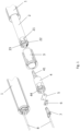
- Figure 1 shows a perspective view of the cloth shaft 1, drive motor 2 and control unit 4 in the assembled state and as an exploded view.
- FIG. 1 shows the control unit 4 in two perspective views.
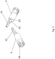
- Figure 3 shows the side view of the roller shaft 1, drive motor 2 and control unit 4 in the assembled state and as an exploded view.
- a drive motor 2 which in the illustrated embodiment is a tubular motor, is inserted into the fabric shaft 1.
- the output of the drive motor 2 is formed by a race 21.
- the end of the drive motor 2 facing away from the fabric shaft 1 is formed by the motor head 22, through which the reaction torque occurring during the movement of the sun protection element is dissipated.
- the sleeve 3 is pushed onto the drive motor 2, which is compressed when inserted into the fabric shaft 1 and forms a positive connection with the race 21 of the drive motor 2.
- This positive connection between the sleeve 3 and the race 21 creates a rotationally fixed connection between the race 21 and the sleeve 3.
- the sleeve 3 is designed and contoured in such a way that, when inserted into the fabric shaft 1, it forms a positive connection with the fabric shaft 1, so that a rotationally fixed connection is also created between the sleeve 3 and the fabric shaft 1.
- the fabric shaft 1 By actuating the drive motor 2 and thus by rotating the race 21, the fabric shaft 1 is rotated accordingly about its longitudinal axis and in this way an awning fabric wound up on the fabric shaft 1 can be unwound or wound up, i.e. the sun protection element can be moved between a retracted and an extended position by means of the drive motor 2.
- the control unit 4 which serves to control and energize the drive motor 2, is connected in a rotationally fixed manner to the motor head 22 of the drive motor.
- the control unit 4 is positively connected to the motor head 22.
- the pins 42, 43 arranged on the front side of the control unit 4 facing the motor head 22 engage in corresponding recesses in the motor head 22.
- the pins 42, 43 are in Figure 2 recognizable.
- control unit 4 The electrical connection of the control unit 4 to the drive motor 2 is made via the plug 41 of the control unit 4, which, when mounted, engages in the socket 23 integrated in the motor head 22.
- the control unit 4 has a module for receiving and processing radio signals according to one or more standardized communication protocols.
- the received radio signals are directly converted by the control unit 4 into control commands for actuating the drive motor 2.
- the control unit 4 can be addressed via radio, allowing the sun protection system to be operated via a radio remote control.
- the power supply to the control unit 4 and, via the control unit 4, also to the drive motor 2 is provided via a plug 7, which is connected to a power supply via cable 8.
- the plug 7 is plugged into a corresponding socket 44 integrated into the control unit 4.
- the axial securing of the plug 7 in the receiving socket 44 is ensured by a strain relief 5.
- This strain relief 5 of the plug 7 is screwed onto the front side of the control unit 4 facing away from the drive motor 2 after the plug 7 has been inserted into the receiving socket 44 in the control unit 4.
- a square 6 is also screwed to the strain relief 5 and the end of the control unit 4 facing away from the drive motor 2.
- the screw connection between the square 6 and the control unit 4 creates a rotationally fixed connection between the square 6 and the control unit 4. Since the control unit 4 is in turn rotationally fixedly coupled to the motor head 22 of the drive motor 2, the control unit thus forms a torque bridge between the drive motor 2 and a torque-absorbing foundation of the sun protection system.
- the reaction torque of the drive motor 2 occurring during the movement of the sun protection element is diverted directly or indirectly via the control unit 4 to a fixed element of the sun protection system, to which the control unit 4 is rotationally fixedly coupled when installed.
- the square 6 is screwed to the control unit 4, by means of which a positive and therefore rotationally fixed connection is established to a torque-absorbing foundation of the sun protection system (not shown in the figures).
- the sleeve 3 is equipped with several longitudinal slots so that the sleeve 3 can be compressed when the arrangement is inserted into the fabric shaft 1 and can be deformed to such an extent that the inner contour of the sleeve 3 creates a form-fitting connection with the outer circumference of the raceway 21, thereby creating a rotationally fixed connection between the raceway 21 of the drive motor 2 and the sleeve 3. which in turn lies positively and non-rotatably in the cloth shaft enclosing the sleeve 3.
- the inner contour of the sleeve 3 engages with a circumferential undercut arranged on the race. This creates axial locking of the entire assembly consisting of sleeve 3, drive motor 2, and control unit 4 in the fabric shaft 1.
- control unit 4 and the motor head 22 of the drive motor 2 are screwed together.
- a positive connection and/or a force connection as well as a screw connection of the control unit 4 and the motor head 22 of the drive motor 2 can also be combined to create a rotationally fixed connection between the control unit 4 and the motor head 22 of the drive motor 2.
Landscapes
- Engineering & Computer Science (AREA)
- Structural Engineering (AREA)
- Microelectronics & Electronic Packaging (AREA)
- Power Engineering (AREA)
- Architecture (AREA)
- Civil Engineering (AREA)
- Operating, Guiding And Securing Of Roll- Type Closing Members (AREA)
Priority Applications (1)
| Application Number | Priority Date | Filing Date | Title |
|---|---|---|---|
| EP23217263.5A EP4571037A1 (fr) | 2023-12-15 | 2023-12-15 | Installation de protection solaire dotée d'une unité de commande fixée au moteur |
Applications Claiming Priority (1)
| Application Number | Priority Date | Filing Date | Title |
|---|---|---|---|
| EP23217263.5A EP4571037A1 (fr) | 2023-12-15 | 2023-12-15 | Installation de protection solaire dotée d'une unité de commande fixée au moteur |
Publications (1)
| Publication Number | Publication Date |
|---|---|
| EP4571037A1 true EP4571037A1 (fr) | 2025-06-18 |
Family
ID=89223413
Family Applications (1)
| Application Number | Title | Priority Date | Filing Date |
|---|---|---|---|
| EP23217263.5A Pending EP4571037A1 (fr) | 2023-12-15 | 2023-12-15 | Installation de protection solaire dotée d'une unité de commande fixée au moteur |
Country Status (1)
| Country | Link |
|---|---|
| EP (1) | EP4571037A1 (fr) |
Citations (2)
| Publication number | Priority date | Publication date | Assignee | Title |
|---|---|---|---|---|
| EP1516410B1 (fr) | 2002-06-27 | 2011-05-11 | Somfy SAS | Actionneur electrique |
| EP3450672A1 (fr) | 2017-08-30 | 2019-03-06 | WAREMA Renkhoff SE | Installation de protection solaire pourvue d'arbre à toile |
-
2023
- 2023-12-15 EP EP23217263.5A patent/EP4571037A1/fr active Pending
Patent Citations (2)
| Publication number | Priority date | Publication date | Assignee | Title |
|---|---|---|---|---|
| EP1516410B1 (fr) | 2002-06-27 | 2011-05-11 | Somfy SAS | Actionneur electrique |
| EP3450672A1 (fr) | 2017-08-30 | 2019-03-06 | WAREMA Renkhoff SE | Installation de protection solaire pourvue d'arbre à toile |
Similar Documents
| Publication | Publication Date | Title |
|---|---|---|
| EP3388610A1 (fr) | Ensemble arbre, dispositif de fermeture ou de protection ainsi que jeu de montage | |
| EP2199484B1 (fr) | Contrôle des appareils électriques par telecommande dans un dispositif d'ombrage | |
| EP0082302B1 (fr) | Dispositif de protection contre le rayonnement solaire et/ou les intempéries | |
| DE4407342C2 (de) | Verdunkelungsvorrichtung mit einer Markise, einer Außenjalousie o. dgl. | |
| EP1069257B1 (fr) | Dispositif de protection solaire commandé par un capteur | |
| EP1091079A2 (fr) | Système de contrôle pour unités d'entraínement à moteur pour un dispositif d'occultation ou d'obscurcissement | |
| EP1914365B1 (fr) | Installation de protection contre le soleil ou la pluie | |
| EP4571037A1 (fr) | Installation de protection solaire dotée d'une unité de commande fixée au moteur | |
| DE20217608U1 (de) | Rohrmotor-Antriebsbaugruppe | |
| EP4368807B1 (fr) | Ensemble de vitrage isolant avec protection solaire ou rideau d'obscurcissement intégré | |
| WO2009100735A1 (fr) | Système d'entraînement électrique pour volet de fenêtre battant ou coulissant | |
| DE102015117707A1 (de) | Antriebsvorrichtung zum Antreiben einer Verdunklungsvorrichtung, insbesondere eines Rollladens oder einer Jalousie | |
| DE29904106U1 (de) | Steuerungssystem einer Verdunkelungs- und/oder Sicherungsanlage | |
| DE4105865A1 (de) | Vorrichtung zum auf- und abwickeln von behaengen, insbesondere markisenstoffen, rollaeden, gittern oder dergleichen | |
| EP4365404B1 (fr) | Ensemble de vitrage isolant avec protection solaire ou rideau d'obscurcissement intégré | |
| DE102015017190B4 (de) | Antriebsvorrichtung zum Antreiben eines Rollladens | |
| DE202007005567U1 (de) | Markise | |
| EP4421263B1 (fr) | Store avec arbre flottant à connexion par enfichage intégrée | |
| DE19544894C1 (de) | Markise mit einem vertikal ausschwenkbaren Arm | |
| DE20214076U1 (de) | Vorrichtung zum Abschirmen eines Raumes | |
| DE202012101593U1 (de) | Antriebsmodul für rollo- oder jalousienartige Verdunklungsanordnungen | |
| DE19809025C2 (de) | Fassadenrollo und Führungsschiene für ein Fassadenrollo | |
| WO2011086084A1 (fr) | Dispositif de store | |
| DE202008016841U1 (de) | Elektrisch betreibbarer Rollladen | |
| EP4365403A2 (fr) | Ensemble de vitrage isolant avec protection solaire ou rideau d'obscurcissement intégré |
Legal Events
| Date | Code | Title | Description |
|---|---|---|---|
| PUAI | Public reference made under article 153(3) epc to a published international application that has entered the european phase |
Free format text: ORIGINAL CODE: 0009012 |
|
| STAA | Information on the status of an ep patent application or granted ep patent |
Free format text: STATUS: THE APPLICATION HAS BEEN PUBLISHED |
|
| AK | Designated contracting states |
Kind code of ref document: A1 Designated state(s): AL AT BE BG CH CY CZ DE DK EE ES FI FR GB GR HR HU IE IS IT LI LT LU LV MC ME MK MT NL NO PL PT RO RS SE SI SK SM TR |
|
| STAA | Information on the status of an ep patent application or granted ep patent |
Free format text: STATUS: REQUEST FOR EXAMINATION WAS MADE |
|
| 17P | Request for examination filed |
Effective date: 20251211 |
|
| GRAP | Despatch of communication of intention to grant a patent |
Free format text: ORIGINAL CODE: EPIDOSNIGR1 |
|
| STAA | Information on the status of an ep patent application or granted ep patent |
Free format text: STATUS: GRANT OF PATENT IS INTENDED |