EP4571111A1 - Akustische haube für einen verdichter und verfahren zur herstellung eines schaumstoffmaterials zur herstellung der akustischen haube - Google Patents
Akustische haube für einen verdichter und verfahren zur herstellung eines schaumstoffmaterials zur herstellung der akustischen haube Download PDFInfo
- Publication number
- EP4571111A1 EP4571111A1 EP23307224.8A EP23307224A EP4571111A1 EP 4571111 A1 EP4571111 A1 EP 4571111A1 EP 23307224 A EP23307224 A EP 23307224A EP 4571111 A1 EP4571111 A1 EP 4571111A1
- Authority
- EP
- European Patent Office
- Prior art keywords
- semi
- acoustic hood
- shell
- density
- shells
- Prior art date
- Legal status (The legal status is an assumption and is not a legal conclusion. Google has not performed a legal analysis and makes no representation as to the accuracy of the status listed.)
- Pending
Links
Images


Classifications
-
- F—MECHANICAL ENGINEERING; LIGHTING; HEATING; WEAPONS; BLASTING
- F04—POSITIVE - DISPLACEMENT MACHINES FOR LIQUIDS; PUMPS FOR LIQUIDS OR ELASTIC FLUIDS
- F04B—POSITIVE-DISPLACEMENT MACHINES FOR LIQUIDS; PUMPS
- F04B39/00—Component parts, details, or accessories, of pumps or pumping systems specially adapted for elastic fluids, not otherwise provided for in, or of interest apart from, groups F04B25/00 - F04B37/00
- F04B39/0027—Pulsation and noise damping means
- F04B39/0033—Pulsation and noise damping means with encapsulations
-
- B—PERFORMING OPERATIONS; TRANSPORTING
- B29—WORKING OF PLASTICS; WORKING OF SUBSTANCES IN A PLASTIC STATE IN GENERAL
- B29B—PREPARATION OR PRETREATMENT OF THE MATERIAL TO BE SHAPED; MAKING GRANULES OR PREFORMS; RECOVERY OF PLASTICS OR OTHER CONSTITUENTS OF WASTE MATERIAL CONTAINING PLASTICS
- B29B17/00—Recovery of plastics or other constituents of waste material containing plastics
- B29B17/0026—Recovery of plastics or other constituents of waste material containing plastics by agglomeration or compacting
- B29B17/0036—Recovery of plastics or other constituents of waste material containing plastics by agglomeration or compacting of large particles, e.g. beads, granules, pellets, flakes, slices
-
- B—PERFORMING OPERATIONS; TRANSPORTING
- B29—WORKING OF PLASTICS; WORKING OF SUBSTANCES IN A PLASTIC STATE IN GENERAL
- B29B—PREPARATION OR PRETREATMENT OF THE MATERIAL TO BE SHAPED; MAKING GRANULES OR PREFORMS; RECOVERY OF PLASTICS OR OTHER CONSTITUENTS OF WASTE MATERIAL CONTAINING PLASTICS
- B29B17/00—Recovery of plastics or other constituents of waste material containing plastics
- B29B17/0026—Recovery of plastics or other constituents of waste material containing plastics by agglomeration or compacting
- B29B17/0042—Recovery of plastics or other constituents of waste material containing plastics by agglomeration or compacting for shaping parts, e.g. multilayered parts with at least one layer containing regenerated plastic
-
- B—PERFORMING OPERATIONS; TRANSPORTING
- B29—WORKING OF PLASTICS; WORKING OF SUBSTANCES IN A PLASTIC STATE IN GENERAL
- B29C—SHAPING OR JOINING OF PLASTICS; SHAPING OF MATERIAL IN A PLASTIC STATE, NOT OTHERWISE PROVIDED FOR; AFTER-TREATMENT OF THE SHAPED PRODUCTS, e.g. REPAIRING
- B29C44/00—Shaping by internal pressure generated in the material, e.g. swelling or foaming ; Producing porous or cellular expanded plastics articles
- B29C44/34—Auxiliary operations
- B29C44/3461—Making or treating expandable particles
-
- F—MECHANICAL ENGINEERING; LIGHTING; HEATING; WEAPONS; BLASTING
- F04—POSITIVE - DISPLACEMENT MACHINES FOR LIQUIDS; PUMPS FOR LIQUIDS OR ELASTIC FLUIDS
- F04C—ROTARY-PISTON, OR OSCILLATING-PISTON, POSITIVE-DISPLACEMENT MACHINES FOR LIQUIDS; ROTARY-PISTON, OR OSCILLATING-PISTON, POSITIVE-DISPLACEMENT PUMPS
- F04C29/00—Component parts, details or accessories of pumps or pumping installations, not provided for in groups F04C18/00 - F04C28/00
- F04C29/06—Silencing
- F04C29/063—Sound absorbing materials
-
- B—PERFORMING OPERATIONS; TRANSPORTING
- B29—WORKING OF PLASTICS; WORKING OF SUBSTANCES IN A PLASTIC STATE IN GENERAL
- B29C—SHAPING OR JOINING OF PLASTICS; SHAPING OF MATERIAL IN A PLASTIC STATE, NOT OTHERWISE PROVIDED FOR; AFTER-TREATMENT OF THE SHAPED PRODUCTS, e.g. REPAIRING
- B29C44/00—Shaping by internal pressure generated in the material, e.g. swelling or foaming ; Producing porous or cellular expanded plastics articles
- B29C44/34—Auxiliary operations
- B29C44/36—Feeding the material to be shaped
- B29C44/38—Feeding the material to be shaped into a closed space, i.e. to make articles of definite length
- B29C44/44—Feeding the material to be shaped into a closed space, i.e. to make articles of definite length in solid form
- B29C44/445—Feeding the material to be shaped into a closed space, i.e. to make articles of definite length in solid form in the form of expandable granules, particles or beads
-
- B—PERFORMING OPERATIONS; TRANSPORTING
- B29—WORKING OF PLASTICS; WORKING OF SUBSTANCES IN A PLASTIC STATE IN GENERAL
- B29K—INDEXING SCHEME ASSOCIATED WITH SUBCLASSES B29B, B29C OR B29D, RELATING TO MOULDING MATERIALS OR TO MATERIALS FOR MOULDS, REINFORCEMENTS, FILLERS OR PREFORMED PARTS, e.g. INSERTS
- B29K2075/00—Use of PU, i.e. polyureas or polyurethanes or derivatives thereof, as moulding material
-
- B—PERFORMING OPERATIONS; TRANSPORTING
- B29—WORKING OF PLASTICS; WORKING OF SUBSTANCES IN A PLASTIC STATE IN GENERAL
- B29K—INDEXING SCHEME ASSOCIATED WITH SUBCLASSES B29B, B29C OR B29D, RELATING TO MOULDING MATERIALS OR TO MATERIALS FOR MOULDS, REINFORCEMENTS, FILLERS OR PREFORMED PARTS, e.g. INSERTS
- B29K2105/00—Condition, form or state of moulded material or of the material to be shaped
- B29K2105/26—Scrap or recycled material
-
- B—PERFORMING OPERATIONS; TRANSPORTING
- B29—WORKING OF PLASTICS; WORKING OF SUBSTANCES IN A PLASTIC STATE IN GENERAL
- B29K—INDEXING SCHEME ASSOCIATED WITH SUBCLASSES B29B, B29C OR B29D, RELATING TO MOULDING MATERIALS OR TO MATERIALS FOR MOULDS, REINFORCEMENTS, FILLERS OR PREFORMED PARTS, e.g. INSERTS
- B29K2995/00—Properties of moulding materials, reinforcements, fillers, preformed parts or moulds
- B29K2995/0001—Properties of moulding materials, reinforcements, fillers, preformed parts or moulds having particular acoustical properties
- B29K2995/0002—Properties of moulding materials, reinforcements, fillers, preformed parts or moulds having particular acoustical properties insulating
-
- B—PERFORMING OPERATIONS; TRANSPORTING
- B29—WORKING OF PLASTICS; WORKING OF SUBSTANCES IN A PLASTIC STATE IN GENERAL
- B29L—INDEXING SCHEME ASSOCIATED WITH SUBCLASS B29C, RELATING TO PARTICULAR ARTICLES
- B29L2031/00—Other particular articles
- B29L2031/751—Mattresses, cushions
Definitions
- the invention relates to an acoustic hood for a compressor, and for example for a scroll compressor.
- Compressors emit significant noise during the operation, which noise significantly impacts the surrounding of the place where a compressor is installed. Therefore many efforts have been made in recent years in order to reduce the overall noise generated by a compressor.
- the noise emitted to the surrounding may be reduced by means of technical devices located inside the compressor (e.g. mufflers) or by means of soundproof structures that are put on a compressor.
- Exemplary soundproof structures for a compressor are disclosed in KR20130046660A and US2005274569A1 .
- such structures comprise multiple parts connected together in order to form an enclosure that surrounds a compressor in the place where it is installed.
- CN205655414U discloses an idea that an air conditioning compressor may have two noise absorbing layers: a sound absorbing layer and a perforated sound insulation layer.
- the two layers are made of different materials, and thus have different acoustic properties.
- CN209512260U discloses a sound insulation soft bag for a compressor of air conditioning unit.
- the sound insulation soft bag comprises stepped joints which are used in order to improve sound sealing effect.
- the object of the present invention is to provide an acoustic hood for a compressor that has improved sound reducing properties comparing to the solutions known from the prior art.
- an object of the present invention is to provide an acoustic hood, for a compressor and for example for a scroll compressor, which has a simple, reliable and cheap structure, while ensuring an increased sound attenuation of the noise emitted by a compressor located inside the acoustic hood.
- such an acoustic hood also named sound attenuating hood, comprises:
- the first and second semi-shells are configured such that, when a compressor located inside the enclosure is running and a sound wave is generated by the compressor, said sound wave undergoes a first absorbing action while passing through the first inner layer of one of the first and second semi-shells and such that, when the sound wave reaches the respective second outer layer, a first part of said sound wave undergoes a second absorbing action while passing through said second outer layer and a second part of said sound wave is reflected back by said second outer layer and undergoes a third absorbing action within the respective first inner layer.
- a sound wave, emitted by the compressor, that reaches the surrounding is significantly reduced by three absorbing actions.
- each of the first and second semi-shells is formed from a multi-layer foam material comprising a first inner layer which is a sound absorbing and insulating layer and a second outer layer which is a sound absorbing and insulating layer and the fact that the first density is lower than the second density, enhances sound attenuation within each of the first and second semi-shells, notably due to the reflection of a part of the sound waves at the interface between the respective first inner layer and second outer layer and the transmission of a part of the sound waves through the respective second outer layer, and in a wider frequency range than other multi-layers foam materials from the prior art.
- the labyrinth seal provided by the at least one stepped lap joint between the first and second semi-shell reduces the acoustic leaks and therefore improves the sound attenuation.
- the acoustic hood according to the present invention ensures an increased sound attenuation of the noise emitted by a compressor located inside the acoustic hood, while having a simple, reliable and cheap structure.
- the acoustic hood may also include one or more of the following features, taken alone or in combination.
- the acoustic hood is semi rigid. Such a configuration of the acoustic hood allows an easy handling of the acoustic hood and an easy mounting of the acoustic hood on the compressor.
- the first and second densities, the first and second thicknesses and the overall structure of the acoustic hood are designed in such way that the acoustic hood is semi rigid.
- the enclosure defines an inner volume configured to receive the compressor.
- the mechanical properties of the first inner layer of the first semi-shell are substantially identical to the mechanical properties of the first inner layer of the second semi-shell, and the mechanical properties of the second outer layer of the first semi-shell are substantially identical to the mechanical properties of the second outer layer of the second semi-shell.
- a thickness ratio between the first thickness and the second thickness is in range between 1 and 6.
- a density ratio between the second density and the first density is in range between 1.5 and 3.6.
- the first thickness is between 20 mm and 60 mm.
- the second thickness is between 10 mm and 20 mm.
- the first density is between 0,1 g/cm 3 and 0,16 g/cm 3 .
- the second density is between 0,24 g/cm 3 and 0,36 g/cm 3 .
- the multi-layer foam material may advantageously be a suitable polyurethane foam material, selected with desired properties relating to density and elasticity (as measured by a ball rebound test).
- the multi-layer foam material is made from polyurethane foam granules, and for example polyurethane recycled foam granules.
- the acoustic hood minimizes waste generation and contributes to reduce resources and energy consumption.
- the polyurethane foam is a rebonded foam made from discarded mattress waste.
- This waste fraction provides a more homogenous density distribution as the mattress fraction mainly consists of polyether based High-Resilience (HR) foams in a typical density range of 25-45 kg/m 3 before rebonding.
- the mattress fraction typically has a high elasticity with a ball rebound of >50%, whereas Post-Industrial rebonded foam often consists of a much wider density spread - both lower and higher than 25-45 kg/m 3 , as well as lower resilience foams some being polyester based. It is however possible and within the scope of the present invention to use these and other types of re-generated foams with the present invention.
- HR-foams are, despite the homogenous density and elasticity, well known for having a mixed cell structure which makes the quality of the cell labyrinth higher and more complex leading to a better sound absorption.
- the positive sound absorbing effect of the mixed cell structure is being further enhanced by shredding the foam waste into granulates where a typical granulate size is ⁇ 6 - 10 mm whereafter the granulates are pressed to a final density as described.
- waste fraction with described cell structure and granulate size in combination with the final density and thickness combinations, is specifically important to sound insulate in the frequency range of 400 Hz and upwards which results in a significant noise reduction on a compressor in the range of 9-11 dB.
- the first semi-shell comprises a side wall and a top wall and the second semi-shell comprises at least one side wall.
- the top wall of the first semi-shell is configured to cover an upper part of the second semi-shell.
- the inlet piping opening and the outlet piping opening are provided on the second semi-shell, and for example on the at least one side wall of the second semi-shell.
- the bottom part is connected with the side wall of the first semi-shell and the at least one side wall of the second semi-shell through a stepped lap joint formed by the bottom part and the first inner layers and the second outer layers of the first and second semi-shells.
- the first semi-shell and the second semi-shell have respectively a dove tail projection and a dove tail seat in order to obtain a dove tail shaped connection between the top wall of the first semi-shell and the at least one side wall of the second semi-shell.
- the top wall includes the dove tail projection.
- the dove tail projection may be arranged on a lower face of the top wall.
- dove tail projection projects from the top wall towards the bottom part.
- the dove tail seat emerges in an upper face of the second semi-shell.
- the acoustic hood has a roof part located on the top wall of the first semi-shell and provided with a sloped surface configured to be angled at an angle in respect to a horizontal plane when the acoustic hood rests on a horizontal surface.
- the angle is in the range from 1 to 10°.
- the roof part is formed integrally with the top wall of the first semi-shell.
- the acoustic hood comprises a control wiring opening emerging in the enclosure and through which a control wiring of the compressor is adapted to extend.
- the control wiring may include a power cable for the compressor.
- the side wall of the first semi-shell is connected with at least one side wall of the second semi-shell via a basically vertical joint.
- the acoustic hood comprises at least one additional opening, for example formed in a side wall of one of the first and second semi-shells, for an optional equipment of the compressor, such as an oil sight glass.
- the first and second semi-shells are tightened together by at least one fastening belt surrounding the first and second semi-shells.
- the at least one fastening belt extends around the side wall of the first semi-shell and the at least one side wall of the second semi-shell.
- the acoustic hood is configured such that, at the at least one stepped lap joint between the first and second semi-shells, the first inner layer of one of the first and second semi-shells is overlapped with the second outer layers of the other one of the first and second semi-shells.
- the acoustic hood further includes a cover installed over the first and second semi-shells, said cover being made from a water tight and UV proof textile assembled by use of ultrasonic welding, which gives watertight connections.
- a cover installed over the first and second semi-shells, said cover being made from a water tight and UV proof textile assembled by use of ultrasonic welding, which gives watertight connections.
- Polyurethane foam is well-known to be degraded overtime when exposed to direct UV, especially the polyether-based types.
- the open cell structure of polyurethane foam allows unwanted water absorption, which decreases the sound insulating properties.
- a cover, made in a watertight and UV proof textile may be installed over the first and second semi-shells.
- the cover is advantagesouly produced by use of ultrasonic welding, which gives water tight connections even when parts of the textile are connected with each other (in contrary to traditional sewing, where the perforation of a needle compromises the water tight properties).
- Advantagously, the cover is furthermore designed to fit tightly over the first and second semi-shells ensuring that no joints are open for acoustic leakage.
- the granulates are shredded to achieve an average granulate diameter size between 6 and 10 mm and the density range of the not bonded granulates is in the range of 25-45 kg/m 3 , and the elasticity of the mattress waste material prior to being shredded is above 50% in a ball rebound test.
- This mixture has shown to be particular advantageous to sound insulate in the frequency range of 400 Hz and upwards which results in a significant noise reduction on a compressor in the range of 9-11 dB when the foam material is used in an acoustic hood as discussed above.
- a prepolymerized MDI is added to the granulate mix in a process chamber, whereafter the granulate mix with the prepolymerized MDI is transferred to a mold, whereafter the granulate mix and the prepolymerized MDI are pressed in the mold to obtain the desired density, while steam is inytroduced into the mold in order to sterilize the granulate mix and accelerate the curing process of the prepolymerized MDI which acts as an adhesive, has proven advantageous.
- a prepolymerized MDI is added to the granulate mix in a mix chamber, whereafter the granulates are poured into a mould.
- a lid is pressing the height to control the final density of the foam and steam is hereafter added, partly to accelerate the curing of the prepolymer, which acts a glue bonding the granulates together (a well-known processing technology), but especially to sterilize the foam and eliminate any bacteria coming from the potentially contaminated discarded mattresses.
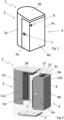
- Figures 1 to 6 show an acoustic hood 2 according to a first embodiment of the present invention.
- the acoustic hood 2 comprises a first semi-shell 3, a second semi-shell 4 and a bottom part 5 that forms an enclosure configured to surround a compressor 6 (see figure 6 ) and for example a scroll compressor such as a refrigeration scroll compressor.
- the enclosure defines an inner volume configured to entirely receive the compressor 6.
- the overall shape and dimensions of the acoustic hood 2 are adapted to the shape and dimensions of the compressor 6 located inside the acoustic hood 2.
- the first semi-shell 3 comprises a side wall 3a and a top wall 3b
- the second semi-shell 4 comprises three rectangular side walls 4a, 4b, 4c configured to be covered by the top wall 3b
- the acoustic hood 2 has a generally cuboid shape with one rounded side wall formed by the side wall 3a.
- the top wall 3b may be formed integrally with the second semi-shell 4 instead of the first semi-shell 3.
- the second semi-shell 4 comprises an inlet piping opening 7 configured to emerge in the enclosure and through which an inlet piping of the compressor 6 is adapted to extend, and also an outlet piping opening 8 configured to emerge in the enclosure and through which an outlet piping of the compressor 6 is adapted to extend.
- the inlet piping opening 7 is formed on the side wall 4a
- the outlet piping opening 8 is formed on the side wall 4b.
- the dimensions and the shapes of the inlet piping opening 7 and the outlet piping opening 8 are designed in such way that the respective inlet and outlet piping are received in them in a tight manner.
- the inlet piping opening 7 and the outlet piping opening 8 may be located on different side walls or on the same side wall or the number of the openings may be different than two.
- the acoustic hood 2 may comprise a control wiring opening (not shown on the drawings) configured to emerge in the enclosure and through which a control wiring, such as electric wires, of the compressor 6 is adapted to extend. Said control wiring opening may for example be formed in the side wall 4b.
- the acoustic hood 2 may also comprise an additional opening, for example formed in a side wall of one of the first and second semi-shells 3, 4, for an optional equipment of the compressor 6, such as an oil sight glass.
- An additional opening for a power cable for the compressor 6 may be located in the bottom part 5 (it is preferred when the compressor 6 is mounted on rails) or in one of the semi -shells 3, 4 (it is preferred when the compressor is mounted to a horizontal plane).
- the inlet piping opening 7 and the outlet piping opening 8 should be carried out with precision, and particularly should have correct dimension and angle (indeed, for example too big hole will compromise the acoustic performance).
- the typical processing method to obtain said openings is a 2D cutting technology, e.g. waterjet cutting or string cutting, which do not allow an angled hole (except if a multi axled waterjet cutter is used, but that is both rare and expensive method to use).
- each of the first and second semi-shells 3, 4 is formed by a multi-layer foam material respectively comprising a first inner layer 9a, 9b having a first density and a first thickness d1 and a second outer layer 11a, 11b having a second density and a second thickness d2.
- the first inner layer 9a, 9b of each of the first and second semi-shells 3, 4 is a sound absorbing and insulating layer
- the second outer layer 11a, 11b of each of the first and second semi-shells 3, 4 is a sound absorbing and insulating layer.
- the multi-layer foam material of each of the first and second semi-shells 3, 4 may be made from polyurethane recycled foam granules.
- the side wall 3a and the top wall 3b of the first semi-shell 3 are formed by the first inner layer 9a and the second outer layer 11a, while the side walls 4a, 4b, 4c of the second semi-shell 4 are formed by the first inner layer 9b and the second outer layer 11b.
- the top wall 3b has a dove tail projection 12 formed by the first inner layer 9a and the second outer layer 11a and projecting from the top wall 3b towards the bottom part 5.
- the second semi-shell 4 includes a dove tail seat 13 defined by the side walls 4a, 4b, 4c and configured to cooperate with the dove tail projection 12 in order to obtain a dove tail shaped connection between the first semi-shell 3 and the second semi-shell 4, and thus a good adjustment and better stability of the acoustic hood 2.
- the dove tail seat 13 emerges in an upper face of the second semi-shell 4.
- the first density is lower than the second density and, and the first thickness d1 is higher than the second thickness d2.
- the first density is between 0,1 g/cm 3 and 0,16 g/cm 3 , for example 0,13 g/cm 3
- the second density is between 0,24 g/cm 3 and 0,36 g/cm 3 , for example 0,3 g/cm 3
- the first thickness d1 may be between 20 mm and 60 mm, for example 40 mm
- the second thickness d2 may be between 10 mm and 20 mm, for example 15 mm.
- a density ratio of the second density to the first density is in range between 1.5 and 3.6, and for example is 2,3, and a thickness ratio of the first thickness d1 to the second thickness d2 is in range between 1 and 6, and for example is 2,7.
- the mechanical properties of the first inner layer 9a of the first semi-shell 3 are substantially identical to the mechanical properties of the first inner layer 9b of the second semi-shell 4, and the mechanical properties of the second outer layer 11a of the first semi-shell 3 are substantially identical to the mechanical properties of the second outer layer 11b of the second semi-shell 4.
- at least one inner/outer layer may have different properties than the other inner/outer layer, for example in order to obtain different sound attenuation in different directions or in order to obtain an acoustic hood 2 with a variable rigidity.
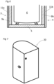
- Figures 3a and 3b shows the structure of the multi-layer foam materials of the first and second semi-shells 3, 4 and the way how the multi-layer foam material of each of the first and second semi-shells 3, 4 attenuates the noise generated by the compressor 6 located inside the acoustic hood 2.
- the first semi-shell 3 is connected with the second semi-shell through vertical stepped lap joints formed by the first inner layers 9a, 9b and the second outer layers 11a, 11b of the first and second semi-shells 3, 4.
- Figures 4 and 5 show cross section views of exemplary embodiments of vertical stepped lap joints between the first and second semi-shells 3, 4, wherein on figure 4 the second outer layer 11a of the first semi-shell 3 overlaps with the first inner layers 9b of the second semi-shell 4 and on figure 5 the first inner layer 9a of the first semi-shell 3 overlaps with the second outer layers 11b of the second semi-shell 4.
- the offset X of the overlapping may be in range from 1 to 20 mm.
- acoustic leaks at the joints between the first inner layer 9a and the second outer layer 11a of the first semi-shell 3 and the first inner layer 9b and the second outer layer 11b of the second semi-shell 4 may be reduced, as a "labyrinth" seal is provided, i.e. a sound wave cannot pass through the multi-layer foam material, at said joints, without a change in the direction of movement.
- a "labyrinth" seal is provided, i.e. a sound wave cannot pass through the multi-layer foam material, at said joints, without a change in the direction of movement.
- the pathway of a sound wave through the multi-layer foam material, at a joint between the first and second semi-shells 3, 4 is not a straight line.
- the bottom part 5 is connected with the side wall 3a of the first semi-shell 3 and the side walls 4a, 4b, 4c of the second semi-shell 4 through a horizontal stepped lap joint formed by the bottom part 5 and the first inner layers 9a, 9b and the second outer layers 11a, 11b of the first and second semi-shells 3, 4.
- the second outer layers 11a, 11b of the first and second semi-shells 3, 4 overlap with the bottom part 5 at said horizontal stepped lap joint.
- the acoustic hood 2 may further includes a cover 20 (shown on figure 7 ) configured to be installed over the first and second semi-shells 3, 4 and being made from a water tight and UV proof textile.
- the cover 20 is advantagesouly produced by use of ultrasonic welding, which gives water tight connections even when parts of the textile are connected with each other (in contrary to traditional sewing, where the perforation of a needle compromises the water tight properties).
- the cover 20 is furthermore designed to fit tightly over the first and second semi-shells 3, 4 ensuring that no joints are open for acoustic leakage.
- FIG. 8 shows a side view of the acoustic hood 2 according to a second embodiment of the present invention.
- the acoustic hood 2 has a roof part 14 located on the top wall 3b of the first semi-shell 3.
- the roof part 14 has a sloped surface 15 which is configured to be angled at an angle A in respect to a horizontal plane when the acoustic hood 2 rests on a horizontal surface.
- the angle A may be in range from 1 to 10°.
- the roof part 14 may have other shapes allowing the water to free fall under the gravity from the acoustic hood 2, or may be formed integrally with the top wall 3b of the first semi-shell 3.
- Figure 9 shows a perspective view of an acoustic hood 2 according to a third embodiment of the present invention.
- the acoustic hood 2 is provided with two fastening belts 16 that surround the first and second semi-shells 3, 4 and tighten the first and second semi-shells 3, 4 together in order to provide a better stabilization for the acoustic hood 2.
- the fastening belts 16 extend around the side walls 3a, 4a, 4b, 4c of the first and second semi-shells 3, 4.
- the acoustic hood 2 may include only one fastening belt 16 or more than two fastening belts 16.
- the acoustic hood 2 may be configured to receive a piston compressor or an oil-free compressor, and may be applied for compressors from other applications than refrigeration, e.g. heat pump applications.
Landscapes
- Engineering & Computer Science (AREA)
- Mechanical Engineering (AREA)
- Environmental & Geological Engineering (AREA)
- General Engineering & Computer Science (AREA)
- Soundproofing, Sound Blocking, And Sound Damping (AREA)
Priority Applications (2)
| Application Number | Priority Date | Filing Date | Title |
|---|---|---|---|
| EP23307224.8A EP4571111A1 (de) | 2023-12-15 | 2023-12-15 | Akustische haube für einen verdichter und verfahren zur herstellung eines schaumstoffmaterials zur herstellung der akustischen haube |
| PCT/EP2024/085908 WO2025125419A1 (en) | 2023-12-15 | 2024-12-12 | An acoustic hood for a compressor |
Applications Claiming Priority (1)
| Application Number | Priority Date | Filing Date | Title |
|---|---|---|---|
| EP23307224.8A EP4571111A1 (de) | 2023-12-15 | 2023-12-15 | Akustische haube für einen verdichter und verfahren zur herstellung eines schaumstoffmaterials zur herstellung der akustischen haube |
Publications (1)
| Publication Number | Publication Date |
|---|---|
| EP4571111A1 true EP4571111A1 (de) | 2025-06-18 |
Family
ID=89542045
Family Applications (1)
| Application Number | Title | Priority Date | Filing Date |
|---|---|---|---|
| EP23307224.8A Pending EP4571111A1 (de) | 2023-12-15 | 2023-12-15 | Akustische haube für einen verdichter und verfahren zur herstellung eines schaumstoffmaterials zur herstellung der akustischen haube |
Country Status (2)
| Country | Link |
|---|---|
| EP (1) | EP4571111A1 (de) |
| WO (1) | WO2025125419A1 (de) |
Citations (9)
| Publication number | Priority date | Publication date | Assignee | Title |
|---|---|---|---|---|
| US5272285A (en) * | 1992-08-20 | 1993-12-21 | Scott Mfg., Inc. | Sound attenuating machinery cover |
| US5588810A (en) * | 1995-09-01 | 1996-12-31 | Bristol Compressors, Inc. | Low noise refrigerant compressor |
| US20040053032A1 (en) * | 2000-07-11 | 2004-03-18 | Rudolf Weingartner | Method for producing foam products |
| US20050274569A1 (en) | 2004-05-14 | 2005-12-15 | Seel Robert V | Compressor sound attenuation enclosure |
| KR20130046660A (ko) | 2011-10-28 | 2013-05-08 | 엘지전자 주식회사 | 압축기의 방음구조 |
| US20130156614A1 (en) * | 2011-12-16 | 2013-06-20 | Emerson Climate Technologies, Inc. | Sound enclosure for enclosing a compressor assembly |
| CN205655414U (zh) | 2016-04-06 | 2016-10-19 | 武汉蓝格包装材料有限公司 | 一种空调压缩机隔音棉 |
| EP3290697A1 (de) * | 2015-04-28 | 2018-03-07 | Daikin Industries, Ltd. | Schalldämmende abdeckung des kompressors für klimaanlage |
| CN209512260U (zh) | 2019-01-12 | 2019-10-18 | 上海环境保护有限公司 | 一种用于空调机组螺杆式压缩机隔声软包 |
-
2023
- 2023-12-15 EP EP23307224.8A patent/EP4571111A1/de active Pending
-
2024
- 2024-12-12 WO PCT/EP2024/085908 patent/WO2025125419A1/en active Pending
Patent Citations (9)
| Publication number | Priority date | Publication date | Assignee | Title |
|---|---|---|---|---|
| US5272285A (en) * | 1992-08-20 | 1993-12-21 | Scott Mfg., Inc. | Sound attenuating machinery cover |
| US5588810A (en) * | 1995-09-01 | 1996-12-31 | Bristol Compressors, Inc. | Low noise refrigerant compressor |
| US20040053032A1 (en) * | 2000-07-11 | 2004-03-18 | Rudolf Weingartner | Method for producing foam products |
| US20050274569A1 (en) | 2004-05-14 | 2005-12-15 | Seel Robert V | Compressor sound attenuation enclosure |
| KR20130046660A (ko) | 2011-10-28 | 2013-05-08 | 엘지전자 주식회사 | 압축기의 방음구조 |
| US20130156614A1 (en) * | 2011-12-16 | 2013-06-20 | Emerson Climate Technologies, Inc. | Sound enclosure for enclosing a compressor assembly |
| EP3290697A1 (de) * | 2015-04-28 | 2018-03-07 | Daikin Industries, Ltd. | Schalldämmende abdeckung des kompressors für klimaanlage |
| CN205655414U (zh) | 2016-04-06 | 2016-10-19 | 武汉蓝格包装材料有限公司 | 一种空调压缩机隔音棉 |
| CN209512260U (zh) | 2019-01-12 | 2019-10-18 | 上海环境保护有限公司 | 一种用于空调机组螺杆式压缩机隔声软包 |
Also Published As
| Publication number | Publication date |
|---|---|
| WO2025125419A1 (en) | 2025-06-19 |
Similar Documents
| Publication | Publication Date | Title |
|---|---|---|
| US7398855B2 (en) | Compressor sound attenuation enclosure | |
| JP4767209B2 (ja) | 防音カバー | |
| EP4571111A1 (de) | Akustische haube für einen verdichter und verfahren zur herstellung eines schaumstoffmaterials zur herstellung der akustischen haube | |
| CN104048367A (zh) | 压缩机减振降噪装置 | |
| TW201717830A (zh) | 具有隔音元件之清潔設備 | |
| CN111247379B (zh) | 制冷循环装置用单元、制冷循环装置及电气设备 | |
| JP2002243211A (ja) | 空気調和機用圧縮機の吸音材 | |
| JP4741889B2 (ja) | 防音換気扇フード | |
| CN204006411U (zh) | 压缩机减振降噪装置 | |
| JP3081080B2 (ja) | 防音ユニット | |
| JP2943676B2 (ja) | 冷蔵庫 | |
| JP3566609B2 (ja) | 厨芥粉砕機を備える流し台 | |
| CN210397025U (zh) | 真空包隔压缩机及空调 | |
| CN219460970U (zh) | 一种底座结构及料理机 | |
| CN118391230A (zh) | 一种降噪结构、压缩机装置及换热设备 | |
| KR101447294B1 (ko) | 압축기의 방음장치 | |
| CN108661477A (zh) | 自动门 | |
| KR102922633B1 (ko) | 방음부스 | |
| CN223498125U (zh) | 隔音减振结构及净水器 | |
| WO2024257702A1 (ja) | 圧縮機用エンクロージャの製造方法 | |
| WO2024257701A1 (ja) | 圧縮機用エンクロージャ及び圧縮機ユニット | |
| CN219810057U (zh) | 燃气热水器 | |
| CN220302324U (zh) | 一种净水增压泵降噪结构及净水装置 | |
| CN216522483U (zh) | 一种具有降噪结构的热泵机组 | |
| JP2007240948A (ja) | 騒音低減装置、送風機 |
Legal Events
| Date | Code | Title | Description |
|---|---|---|---|
| PUAI | Public reference made under article 153(3) epc to a published international application that has entered the european phase |
Free format text: ORIGINAL CODE: 0009012 |
|
| STAA | Information on the status of an ep patent application or granted ep patent |
Free format text: STATUS: THE APPLICATION HAS BEEN PUBLISHED |
|
| AK | Designated contracting states |
Kind code of ref document: A1 Designated state(s): AL AT BE BG CH CY CZ DE DK EE ES FI FR GB GR HR HU IE IS IT LI LT LU LV MC ME MK MT NL NO PL PT RO RS SE SI SK SM TR |
|
| STAA | Information on the status of an ep patent application or granted ep patent |
Free format text: STATUS: REQUEST FOR EXAMINATION WAS MADE |
|
| 17P | Request for examination filed |
Effective date: 20251014 |