EP4571114A2 - Système de compresseur avec refroidissement et procédé de fonctionnement d'un système de compresseur - Google Patents
Système de compresseur avec refroidissement et procédé de fonctionnement d'un système de compresseur Download PDFInfo
- Publication number
- EP4571114A2 EP4571114A2 EP24218453.9A EP24218453A EP4571114A2 EP 4571114 A2 EP4571114 A2 EP 4571114A2 EP 24218453 A EP24218453 A EP 24218453A EP 4571114 A2 EP4571114 A2 EP 4571114A2
- Authority
- EP
- European Patent Office
- Prior art keywords
- cooler
- cooling
- compressor
- housing
- coolant
- Prior art date
- Legal status (The legal status is an assumption and is not a legal conclusion. Google has not performed a legal analysis and makes no representation as to the accuracy of the status listed.)
- Pending
Links
Images


Classifications
-
- F—MECHANICAL ENGINEERING; LIGHTING; HEATING; WEAPONS; BLASTING
- F04—POSITIVE - DISPLACEMENT MACHINES FOR LIQUIDS; PUMPS FOR LIQUIDS OR ELASTIC FLUIDS
- F04C—ROTARY-PISTON, OR OSCILLATING-PISTON, POSITIVE-DISPLACEMENT MACHINES FOR LIQUIDS; ROTARY-PISTON, OR OSCILLATING-PISTON, POSITIVE-DISPLACEMENT PUMPS
- F04C29/00—Component parts, details or accessories of pumps or pumping installations, not provided for in groups F04C18/00 - F04C28/00
- F04C29/04—Heating; Cooling; Heat insulation
-
- F—MECHANICAL ENGINEERING; LIGHTING; HEATING; WEAPONS; BLASTING
- F04—POSITIVE - DISPLACEMENT MACHINES FOR LIQUIDS; PUMPS FOR LIQUIDS OR ELASTIC FLUIDS
- F04C—ROTARY-PISTON, OR OSCILLATING-PISTON, POSITIVE-DISPLACEMENT MACHINES FOR LIQUIDS; ROTARY-PISTON, OR OSCILLATING-PISTON, POSITIVE-DISPLACEMENT PUMPS
- F04C29/00—Component parts, details or accessories of pumps or pumping installations, not provided for in groups F04C18/00 - F04C28/00
- F04C29/04—Heating; Cooling; Heat insulation
- F04C29/042—Heating; Cooling; Heat insulation by injecting a fluid
-
- F—MECHANICAL ENGINEERING; LIGHTING; HEATING; WEAPONS; BLASTING
- F04—POSITIVE - DISPLACEMENT MACHINES FOR LIQUIDS; PUMPS FOR LIQUIDS OR ELASTIC FLUIDS
- F04C—ROTARY-PISTON, OR OSCILLATING-PISTON, POSITIVE-DISPLACEMENT MACHINES FOR LIQUIDS; ROTARY-PISTON, OR OSCILLATING-PISTON, POSITIVE-DISPLACEMENT PUMPS
- F04C18/00—Rotary-piston pumps specially adapted for elastic fluids
- F04C18/08—Rotary-piston pumps specially adapted for elastic fluids of intermeshing-engagement type, i.e. with engagement of co-operating members similar to that of toothed gearing
- F04C18/12—Rotary-piston pumps specially adapted for elastic fluids of intermeshing-engagement type, i.e. with engagement of co-operating members similar to that of toothed gearing of other than internal-axis type
- F04C18/14—Rotary-piston pumps specially adapted for elastic fluids of intermeshing-engagement type, i.e. with engagement of co-operating members similar to that of toothed gearing of other than internal-axis type with toothed rotary pistons
- F04C18/16—Rotary-piston pumps specially adapted for elastic fluids of intermeshing-engagement type, i.e. with engagement of co-operating members similar to that of toothed gearing of other than internal-axis type with toothed rotary pistons with helical teeth, e.g. chevron-shaped, screw type
-
- F—MECHANICAL ENGINEERING; LIGHTING; HEATING; WEAPONS; BLASTING
- F04—POSITIVE - DISPLACEMENT MACHINES FOR LIQUIDS; PUMPS FOR LIQUIDS OR ELASTIC FLUIDS
- F04C—ROTARY-PISTON, OR OSCILLATING-PISTON, POSITIVE-DISPLACEMENT MACHINES FOR LIQUIDS; ROTARY-PISTON, OR OSCILLATING-PISTON, POSITIVE-DISPLACEMENT PUMPS
- F04C23/00—Combinations of two or more pumps, each being of rotary-piston or oscillating-piston type, specially adapted for elastic fluids; Pumping installations specially adapted for elastic fluids; Multi-stage pumps specially adapted for elastic fluids
- F04C23/001—Combinations of two or more pumps, each being of rotary-piston or oscillating-piston type, specially adapted for elastic fluids; Pumping installations specially adapted for elastic fluids; Multi-stage pumps specially adapted for elastic fluids of similar working principle
-
- F—MECHANICAL ENGINEERING; LIGHTING; HEATING; WEAPONS; BLASTING
- F04—POSITIVE - DISPLACEMENT MACHINES FOR LIQUIDS; PUMPS FOR LIQUIDS OR ELASTIC FLUIDS
- F04C—ROTARY-PISTON, OR OSCILLATING-PISTON, POSITIVE-DISPLACEMENT MACHINES FOR LIQUIDS; ROTARY-PISTON, OR OSCILLATING-PISTON, POSITIVE-DISPLACEMENT PUMPS
- F04C23/00—Combinations of two or more pumps, each being of rotary-piston or oscillating-piston type, specially adapted for elastic fluids; Pumping installations specially adapted for elastic fluids; Multi-stage pumps specially adapted for elastic fluids
- F04C23/02—Pumps characterised by combination with, or adaptation to, specific driving engines or motors
-
- F—MECHANICAL ENGINEERING; LIGHTING; HEATING; WEAPONS; BLASTING
- F04—POSITIVE - DISPLACEMENT MACHINES FOR LIQUIDS; PUMPS FOR LIQUIDS OR ELASTIC FLUIDS
- F04C—ROTARY-PISTON, OR OSCILLATING-PISTON, POSITIVE-DISPLACEMENT MACHINES FOR LIQUIDS; ROTARY-PISTON, OR OSCILLATING-PISTON, POSITIVE-DISPLACEMENT PUMPS
- F04C28/00—Control of, monitoring of, or safety arrangements for, pumps or pumping installations specially adapted for elastic fluids
-
- F—MECHANICAL ENGINEERING; LIGHTING; HEATING; WEAPONS; BLASTING
- F04—POSITIVE - DISPLACEMENT MACHINES FOR LIQUIDS; PUMPS FOR LIQUIDS OR ELASTIC FLUIDS
- F04C—ROTARY-PISTON, OR OSCILLATING-PISTON, POSITIVE-DISPLACEMENT MACHINES FOR LIQUIDS; ROTARY-PISTON, OR OSCILLATING-PISTON, POSITIVE-DISPLACEMENT PUMPS
- F04C29/00—Component parts, details or accessories of pumps or pumping installations, not provided for in groups F04C18/00 - F04C28/00
- F04C29/02—Lubrication; Lubricant separation
-
- F—MECHANICAL ENGINEERING; LIGHTING; HEATING; WEAPONS; BLASTING
- F16—ENGINEERING ELEMENTS AND UNITS; GENERAL MEASURES FOR PRODUCING AND MAINTAINING EFFECTIVE FUNCTIONING OF MACHINES OR INSTALLATIONS; THERMAL INSULATION IN GENERAL
- F16N—LUBRICATING
- F16N39/00—Arrangements for conditioning of lubricants in the lubricating system
- F16N39/02—Arrangements for conditioning of lubricants in the lubricating system by cooling
-
- F—MECHANICAL ENGINEERING; LIGHTING; HEATING; WEAPONS; BLASTING
- F04—POSITIVE - DISPLACEMENT MACHINES FOR LIQUIDS; PUMPS FOR LIQUIDS OR ELASTIC FLUIDS
- F04C—ROTARY-PISTON, OR OSCILLATING-PISTON, POSITIVE-DISPLACEMENT MACHINES FOR LIQUIDS; ROTARY-PISTON, OR OSCILLATING-PISTON, POSITIVE-DISPLACEMENT PUMPS
- F04C2240/00—Components
- F04C2240/30—Casings or housings
-
- F—MECHANICAL ENGINEERING; LIGHTING; HEATING; WEAPONS; BLASTING
- F04—POSITIVE - DISPLACEMENT MACHINES FOR LIQUIDS; PUMPS FOR LIQUIDS OR ELASTIC FLUIDS
- F04C—ROTARY-PISTON, OR OSCILLATING-PISTON, POSITIVE-DISPLACEMENT MACHINES FOR LIQUIDS; ROTARY-PISTON, OR OSCILLATING-PISTON, POSITIVE-DISPLACEMENT PUMPS
- F04C2240/00—Components
- F04C2240/80—Other components
- F04C2240/81—Sensor, e.g. electronic sensor for control or monitoring
-
- F—MECHANICAL ENGINEERING; LIGHTING; HEATING; WEAPONS; BLASTING
- F04—POSITIVE - DISPLACEMENT MACHINES FOR LIQUIDS; PUMPS FOR LIQUIDS OR ELASTIC FLUIDS
- F04C—ROTARY-PISTON, OR OSCILLATING-PISTON, POSITIVE-DISPLACEMENT MACHINES FOR LIQUIDS; ROTARY-PISTON, OR OSCILLATING-PISTON, POSITIVE-DISPLACEMENT PUMPS
- F04C2270/00—Control; Monitoring or safety arrangements
- F04C2270/19—Temperature
Definitions
- the present invention relates to a compressor device for compressing a gas to generate compressed gas, in particular compressed air, wherein the compressor device has a cooling device. Furthermore, the present invention relates to a method for operating a compressor device with a cooling device.
- Compressors for compressing a gas to produce compressed gas are also referred to as compressed gas compressors. They are therefore used to generate the compressed gas, often compressed air. This compressed air, or other compressed gas, is specifically intended for subsequent industrial use. The following explanations regarding compressed air also apply to other compressed gases.
- housing coolers can be provided for cooling the compressor housing or a part thereof, which are often also referred to or designed as jacket coolers.
- a cooling medium which is also synonymously known as Coolant, in particular water
- a compressed gas cooler can be provided, which is arranged in part of a piping system that carries the compressed gas, in particular the compressed air.
- a heat exchanger can be provided, through which a cooling medium or coolant, in particular water, also flows.
- Oil is often also required when generating the compressed gas, in particular for lubricating the components of the compressor.
- Such oil is also heated and can be cooled by an oil cooler, which can in particular have a heat exchanger.
- a cooling medium or coolant, in particular water, also flows through this heat exchanger.
- Efficient cooling can be achieved by connecting all of the aforementioned coolers, with several of each cooler being possible, to a primary cooling circuit.
- the coolers can be connected entirely or partially in parallel, so that one cooler does not receive the already heated water from a previous cooler, which would occur in a series circuit.
- the individual coolers receive their cooling water share based on the flow resistance of their parallel branch.
- the coolers each receive an appropriate amount of coolant, especially water.
- valves can be provided and adjusted to manually adjust the coolant flow to each cooling system.
- adjustments can be time-consuming, as a technician must make or change the relevant settings. The result also depends on the individual skills of the technician.
- a further improvement could be individual cooling, with each cooler having its own cooling circuit.
- each cooler having its own cooling circuit.
- such a solution is complex and therefore not necessarily recommended.
- the present invention is therefore based on the object of addressing at least one of the aforementioned problems.
- a solution is to be proposed in which adapted cooling for a compressor device with a cooling device is created in a simple manner.
- an alternative solution to previously known solutions is to be proposed.
- a compressor device comprising a compressor for compressing a gas to generate compressed gas, in particular compressed air, wherein the compressor has at least one compression stage, and comprising a cooling device.
- the cooling device comprises an oil cooler for cooling oil heated by the compressor, at least one compressed gas cooler for cooling the gas completely or partially compressed to form compressed gas, and at least one housing cooler for cooling a housing or part of the housing of the compressor.
- the oil cooler, the at least one compressed gas cooler, and the at least one housing cooler are each configured to achieve cooling by means of a coolant flow comprising a liquid coolant, in particular water.
- At least one housing cooler control means is provided for individually controlling the cooling flow through the housing cooler.
- the compressor device has a cooling controller configured to control the at least one housing cooler control means such that the at least one cooling flow through the at least one housing cooler is controlled independently of the cooling flow through the oil cooler.
- a compressor device comprising a compressor and a cooling device.
- the compressor which can also be synonymously referred to as a compressed gas compressor, is intended to compress a gas to generate compressed gas.
- an air compressor for generating compressed air is proposed. This generates compressed gas or compressed air in a basically known manner.
- a cooling device which has at least one oil cooler, one compressed gas cooler, and one housing cooler.
- the oil cooler is designed to cool oil heated by the compressor.
- the oil can flow from the compressor through a heat exchanger, where it transfers its heat to a liquid coolant, in particular water, i.e., cooling water.
- the compressed gas cooler of which several can be provided, is provided for cooling the compressed gas.
- the compressed gas flows through this compressed gas cooler and in the process gives off heat to a liquid coolant.
- a compressor it is also conceivable for a compressor to have several compression stages, so that after the first compression stage the gas is brought to a first pressure level, which can also be regarded as compressed gas. In this respect, however, the compressed gas is not yet compressed to the final pressure level, so that it can be assumed that the gas is partially compressed.
- a compressed gas cooler can also be provided for this partially compressed gas, which, as already mentioned, can also be referred to simply as compressed gas, and in this case can be arranged between two compressor stages. If there are at least two compressor stages, at least one more compressed gas cooler can be provided after the second compressor stage to cool the compressed gas released by the aforementioned second compressor stage.
- the housing cooler of which several can be provided, is designed to cool a housing or part of the housing of the compressor.
- the compressor housing can essentially be considered the entire physical configuration of the compressor or part thereof. Therefore, it is not just a housing in the sense of a cover for the compressor, but rather the compressor as a physical object.
- a housing cooler can also contain or refer to coolant channels in the housing of a compressor stage.
- the oil cooler, the at least one compressed gas cooler, and the at least one housing cooler are each configured to achieve cooling by a coolant flow consisting of a liquid coolant, in particular water.
- a coolant flow consisting of a liquid coolant, in particular water.
- Each of these coolers thus has at least one flow channel through which the coolant can flow.
- the coolers mentioned are, in principle, coolers, that use a coolant stream from a liquid coolant for cooling, especially coolers that are cooled by water or cooling water. During operation, a coolant stream flows through each cooler.
- At least one housing cooler control means is provided for individually controlling the cooling flow through the housing cooler, allowing individual control. Its control and thus cooling effect can thus operate independently of the other coolers.
- the compressor device has a cooling control which is configured to control the at least one housing cooler control means such that the at least one cooling flow through the at least one housing cooler is controlled independently of the cooling flow through the oil cooler.
- the cooling control means can be configured such that it is implemented as a programmed control in a corresponding process computer and the process computer is operatively connected to the at least one housing cooler control means.
- the housing cooler control means can be designed as a controllable valve or have such a valve.
- the housing cooler control means can also comprise or be a pump, in particular a controllable one. It can be combined with a controllable valve.
- an individually controllable control means is provided for each coolant flow in order to control each coolant flow individually, so that a cooling output for the oil cooler, the at least one compressed gas cooler, and the at least one housing cooler can be individually controlled.
- one of the coolers e.g. the compressed gas cooler
- one of the coolers e.g. the compressed gas cooler
- the respective coolant flow for each of the two or more sub-coolers can be controlled.
- the sub-coolers are connected in parallel.
- the individual control of a coolant flow through each of the sub-coolers can be designed such that the distribution of an overall coolant flow to the sub-coolers is additionally or exclusively controlled.
- Two housing coolers also known as jacket coolers, can also be connected in series or in parallel. If they are connected in parallel, the coolant flow can be divided between these two housing coolers, with only one control device being provided for both housing coolers.
- a primary cooling circuit is provided for all coolers, in which the housing cooler(s) are connected in whole or in part in parallel with other coolers, in particular the oil cooler.
- this does not preclude, for example, two coolers, for example two housing coolers, which can thus be configured as jacket coolers, from being connected in series.
- Such two jacket coolers connected in series can also be considered a common housing cooler.
- Each control device can be designed as a controllable valve, or as a controllable pump, or some control devices are designed as a controllable valve and others as a controllable pump.
- Each control device can be viewed as an individual control device that can be controlled individually. This allows for constant adjustment of the coolant flow to each cooler, allowing each cooler to be operated at its optimal operating point. This means that each cooler can be operated optimally. If, for example, there is an increased cooling demand for the oil cooler, its coolant flow can be increased without also increasing the coolant flow to the other coolers.
- optimal cooling does not necessarily mean that the temperature is cooled down as much as possible.
- the housing can expand or contract depending on the temperature, which can affect its mechanical function, particularly the size of gaps between elements that move relative to one another. It is particularly important that at least one gap between the compressor housing and the rotors and/or between the rotors is kept within an optimal range. Excessive cooling of the housing leads to shrinkage and thus to contact between the rotor and housing or between the rotors, which would permanently increase the gap. If the housing is cooled too little, an unnecessarily large gap is created between the rotor and housing or between the rotors, which would lead to internal backflow of the already compressed gas.
- the oil cooler it's important that the oil temperature maintains the oil viscosity within an optimal range. If the oil is too cold, power consumption increases, and if the oil is too warm, wear increases.
- Cooling the compressed air after the last compressor stage to an optimal level is also important. Insufficient cooling can result in component damage or the compressed air drying system may not function adequately.
- the proposed solution allows to achieve low electrical power consumption and optimal compressed air outlet temperature.
- a high temperature in the total coolant flow or total coolant flow is often desirable.
- the goal is to transfer as much heat as possible to the heating water, which can be coupled with the total coolant flow or total coolant flow or can be used to save fuel costs for heating, for example.
- this requires raising the temperature level accordingly so that the cooling water can be used for heating purposes. This can be somewhat detrimental to compressor cooling, but can be beneficial when heat demand is high. Both of these requirements can be accommodated by decoupled control of the individual coolers.
- the cooling control is configured to control the at least one housing cooler control means such that the at least one cooling flow through the at least one housing cooler is controlled independently of the at least one cooling flow through the at least one compressed gas cooler.
- This provides further decoupling of the housing cooler. This allows the cooler to be more precisely tailored to cooling the housing and, in particular, to achieve an optimal gap width between the rotor and the housing.
- the cooling control is configured such that a cooling flow is controlled individually only for the at least one housing cooler, in particular by means of the housing cooler control means, while cooling flows for the oil cooler and the at least one compressed gas cooler are not controlled or are controlled only via a common control of an overall coolant flow.
- the housing cooling or jacket cooling can be operated at lower temperatures than the oil cooling.
- the housing cooling or jacket cooling can be operated independently of the oil cooling.
- the compressor has at least one rotor for compressing the compressed gas and at least one compressor gap is formed between the housing and the at least one rotor or between two rotors, which has a variable gap thickness, and the cooling control is configured to control the at least one housing cooler control means such that the gap thickness remains within a predeterminable range and/or that the gap thickness is adjusted to a predeterminable target gap thickness.
- the housing cooling is specifically controlled to ensure that the compressor gap (which was also referred to simply as the gap above) is as optimal as possible. It was discovered that by decoupled control of the housing cooler, the gap thickness can be kept within a range suitable for compressor operation.
- the gap thickness can be recorded for this purpose, or the control can be based on empirical values that can be recorded in preliminary tests.
- the gap thickness can also be controlled using other values.
- the gap thickness can be determined from more easily measurable temperatures and based on empirical values.
- the compressor is a dry-compression compressor and/or a screw compressor.
- a screw compressor is one designed to compress the gas, in particular the air to be compressed, through the movement of two intermeshing screws. This allows for a continuous compression process.
- a turbocompressor can also be used as the compressor.
- the cooling control is configured to detect and/or estimate the gap thickness of the compressor and that the at least one housing cooler control means is controlled as a function of the detected or estimated gap thickness.
- this gap thickness be detected, in particular measured, and fed back.
- the control would then be part of a control loop and could also be referred to as a closed-loop control.
- a suitable sensor can be used for this purpose. Although this is associated with considerable costs, it allows the gap thickness to be measured with high accuracy.
- the gap thickness is also possible to determine the gap thickness using a state observer.
- the state observer can use the inlet temperature of a gas to be compressed flowing into a compressor stage and its volume flow as input variables, and the outlet temperature of the gas that has been at least partially compressed in the compressor stage as output variables.
- the gap thickness is then a state of the state observer, and a comparison between the outlet temperature of the state observer and a recorded, corresponding outlet temperature can be used to compare the states of the state observer or its model. It is also possible to simulate relationships using a model calculation and compare the calculated temperatures with the measured temperatures to determine the gap thickness.
- At least one outlet temperature of the gas compressed completely or partially to compressed gas is detected upon exiting the at least one compressor stage, a preset temperature value for the outlet temperature is determined at which an optimal gap thickness is to be expected, wherein the preset temperature value is determined in particular during operation, and the at least one housing cooler control means is controlled such that the outlet temperature is adjusted to the preset temperature value, in particular that the outlet temperature is regulated to the preset temperature value as the target temperature.
- the outlet temperature allows for a fairly accurate prediction of the gap thickness. Relationships between the outlet temperature and gap thickness can be established in preliminary tests.
- the setpoint value can essentially be chosen as the value at which the optimal gap thickness is expected. Therefore, if the outlet temperature is regulated to the setpoint value, the gap thickness can be expected to be approximately at its optimal value.
- the casing size It is therefore also recommended to check the casing size or to cool it in such a way that the casing size remains constant. This is particularly important for the gap thickness and can be reduced to considering the gap thickness. It has been recognized that it is also possible to record the casing size or gap thickness indirectly via the outlet temperature. In the control system that controls the cooling, the theoretical outlet temperature with the correct gap between the rotors and between the rotors and casing is compared with the recorded temperature, and the cooling is controlled based on this. The theoretical outlet temperature with the correct, i.e. optimal, gap thickness between the rotors and between the rotors and casing can be considered as the specified temperature. For screw compressors in particular, and especially for dry-running ones, the gap thickness should be maintained with particular precision. If possible, the gap thickness should approach zero ⁇ m, and in particular permanently approach zero ⁇ m.
- optimal gap thickness and outlet temperature can depend on other variables, particularly the outside temperature and the throughput of compressed gas. Therefore, according to one aspect, it is proposed to determine the default value during ongoing operation. In particular, it is proposed to determine the default value as a function of a coolant temperature and/or an air intake temperature available over the course of a year. Preferably, it is proposed to determine the default value as a function of an outside temperature and/or a throughput of compressed gas.
- a compressor device which is characterized in that the cooling control is configured to control the at least one housing cooler control means as a function of at least one coolant temperature.
- the cooling control is configured to control the at least one housing cooler control means as a function of at least one coolant temperature.
- the housing cooling is controlled in a targeted manner, because the coolant temperature, in particular, can depend on the cooling result by the housing cooling. Therefore, closed-loop control can also be assumed.
- a setpoint value is specified for the coolant temperature. This also allows the coolant to be regulated to a desired temperature.
- a compressor device comprising a compressor for compressing a gas to generate compressed gas, in particular compressed air, and a cooling device.
- the cooling device comprises an oil cooler for cooling oil heated by the compressor, at least one compressed gas cooler for cooling the gas completely or partially compressed to compressed gas, and at least one housing cooler for cooling a housing or part of the housing of the compressor.
- the oil cooler, the at least one compressed gas cooler, and the at least one housing cooler are each configured to achieve cooling by a coolant flow consisting of a liquid coolant, in particular water. Furthermore, the oil cooler and/or at least one of the housing coolers are connected in series with at least one of the compressed gas coolers, so that a coolant flow flows through these series-connected coolers one after the other.
- At least a partial series connection of several different coolers is provided.
- the series connection of the oil cooler and the pressure gas cooler is proposed. This series connection ensures that the coolant receives a high return temperature, allowing a higher water outlet temperature to be achieved in the overall coolant flow. This allows for better utilization of the resulting waste heat.
- the jacket cooling system and the oil cooler can be sufficiently cooled even at high water inlet temperatures.
- the oil cooler and the housing cooler can still be connected in parallel, thus ensuring that the housing cooler can still be controlled independently of the oil cooler.
- the coolant flow flowing through these series-connected coolers first flows through the oil cooler and then flows through the at least one compressed gas cooler, so that the oil cooler is flowed through with a coolant having a lower temperature than the at least one compressed gas cooler.
- This sequence in particular allows a high outlet temperature to be achieved, as the coolant in the pressure gas cooler is raised to a temperature that would not be achievable by the oil cooler.
- a cooling circuit be provided for providing the coolant at a cooling circuit inlet and for taking back the coolant heated by the coolers at a cooling circuit outlet in order to recool the heated coolant or to supply it for further use, in particular to utilize heat from the coolant, and that the compressor device have a cooling control.
- the cooling control is configured to control the compressor device such that the coolant at the cooling circuit outlet has a temperature of 85-95°C, in particular 90°C to 95°C.
- a corresponding control program can be implemented in the cooling control system, which executes corresponding process steps. Furthermore, such a cooling control system is connected to corresponding control means of the coolers, in particular valves, so that the control means can be controlled by the cooling control system. A connection to at least one pump for driving an overall cooling flow can also be provided.
- the cooling control can be integrated into a control loop or form a closed-loop control.
- Temperatures of 85-95°C, especially 90°C to 95°C can be considered high temperatures, and further references to high temperatures, including other aspects, can be specified using these temperature values. It was particularly recognized that 95°C is high, but still below the temperature of boiling water under atmospheric pressure. A limit of 110°C can also be observed, which may be more relevant, since in a compressor system the cooling water is usually under pressure, so it only evaporates at higher temperatures. It should also be noted that different regulations may apply above 110°C. The temperatures mentioned are therefore specifically intended for cooling water as a coolant.
- the compressor device is constructed such that the coolant first flows through the oil cooler and then flows through at least one of the at least one housing cooler.
- the coolant can therefore first be heated in the oil cooler and then further heated in the housing cooler in order to achieve a high coolant temperature at the cooling circuit outlet.
- the case cooler can consist of multiple case coolers, which can be connected in parallel or in series.
- the further heating of the coolant in the case cooler can occur in either variant and achieve the described effect.
- a plurality of compressed gas coolers are provided and the compressor device is constructed such that the coolant, after flowing through the oil cooler, flows through the plurality of compressed gas coolers, which are in particular connected in parallel, so that the coolant flows through these plurality of compressed gas coolers in parallel.
- the pressure gas coolers further heat the coolant after it has already been heated in the oil cooler.
- each of which can be designed as a heat exchanger or can contain heat exchangers, that both heat exchangers receive the same cool water inlet temperature and can cool the compressed air to almost the water inlet temperature in countercurrent, i.e. in the compressed gas flow that flows through the respective heat exchanger.
- both pressure gas coolers can be used to heat the water, i.e. the cooling water, to the desired temperature if required.
- a compressor device is characterized in that several or more compressed gas coolers are divided into several compressed gas cooler groups, wherein the compressed gas coolers in each compressed gas cooler group are connected in parallel to one another, and the compressed gas cooler groups are connected in series.
- a first and a second compressed gas cooler are connected in parallel to one another and are connected in series to a third and fourth compressed gas cooler, which are connected in parallel to one another.
- compressed gas coolers which are particularly designed as heat exchangers—a feature that can be provided for all compressed gas coolers of all types—receive the coolant at the same water inlet temperature when connected in parallel. In counterflow, they can cool the compressed air to near the water inlet temperature.
- pressure gas coolers of a later or second pressure gas cooler group further heat the coolant after it has already been heated in the pressure gas coolers of the first pressure gas cooler group.
- a method for controlling a compressor device wherein the compressor device has a compressor, in particular a screw compressor, for compressing a gas to generate compressed gas, in particular compressed air, wherein the compressor has at least one compression stage.
- the compressor device also has a cooling device.
- the cooling device comprises an oil cooler for cooling oil heated by the compressor, at least one compressed gas cooler for cooling the gas completely or partially compressed to compressed gas, and at least one housing cooler for cooling a housing or part of the housing of the compressor.
- the oil cooler, the at least one compressed gas cooler, and the at least one housing cooler are each configured to achieve cooling by a coolant flow comprising a liquid coolant, in particular water.
- At least one housing cooler control means is provided for the at least one housing cooler for individually controlling the cooling flow through the housing cooler, and the compressor device comprises a cooling controller.
- the cooling controller controls the at least one housing cooler control means such that the at least one cooling flow through the at least one housing cooler is controlled independently of the cooling flow through the oil cooler.
- the method operates as described in connection with the compressor device.
- the method operates as described for the compressor device or corresponding controller, each of which is configured to execute a corresponding method or method steps.
- the following methods or method components are proposed, the implementation and advantageous effects of which were also described above in connection with aspects of the compressor device.
- a method is proposed in which the cooling control controls a cooling flow individually only for the at least one housing cooler, in particular by means of the housing cooler control means, while cooling flows for the oil cooler and the at least one compressed gas cooler are not controlled or are controlled only via a common control of an overall coolant flow.
- the compressor has at least one rotor for compressing the compressed gas and at least one compressor gap is formed between the housing and the at least one rotor, which has a variable gap thickness, and the cooling control controls the at least one housing cooler control means such that the gap thickness remains within a predeterminable range and/or that the gap thickness is adjusted to a predeterminable target gap thickness.
- the gap thickness of the compressor is detected and/or estimated using the cooling control and that the at least one housing cooler control means is controlled as a function of the detected or estimated gap thickness.
- At least one outlet temperature of the gas compressed wholly or partially to compressed gas is detected upon exiting the at least one compressor stage, a default temperature value for the outlet temperature is determined at which an optimal gap thickness is to be expected, wherein the default temperature value is determined in particular during operation, and the at least one housing cooler control means is controlled in such a way that the outlet temperature is adjusted to the default temperature value, in particular that the outlet temperature is regulated to the default temperature value as the target temperature.
- Fig. 1 shows a compressor device 100 with a compressor 130 with a first and second compressor stage 131 and 132, respectively.
- the compressor 130 and the other elements are shown schematically.
- an intercooler 133 and an aftercooler 134 are provided, which can also be referred to as a compressed air intercooler and a compressed air aftercooler, respectively.
- the intercooler is shown here as part of the compressor 130, since it is arranged between the first and second compressor stages, but it can also be designed as a separate element. Accordingly, the aftercooler 134, which is not shown as part of the compressor 130, can be part of the compressor in another embodiment.
- a first and second jacket cooling system 141 and 142 is provided for cooling the first and second compressor stages 131 and 132, respectively.
- the jacket cooling systems 141 and 142 are integrated into the compressor stages 131 and 132, respectively.
- An oil cooler 135 is also provided.
- the oil cooler 135 is connected to an oil circuit 145 of the compressor 130.
- the connection between the oil circuit 145 and the compressor 130 is not shown in this figure, nor in most other figures.
- a primary cooling circuit 150 is provided with a coolant inlet 151 and a coolant return 152.
- the aforementioned coolers namely the intercooler 133, the aftercooler 134, the first and second jacket coolers 141, 142, and the oil cooler 135, are supplied with cold coolant, in the illustrated example, water, via this primary cooling circuit, namely via the coolant inlet 151.
- the water thus heated by the coolers flows back via the coolant return 152 into a heat sink 154, which is only indicated abstractly.
- the heat sink 154 can, but need not, be a component of the compressor device 100.
- a primary heat exchanger 156 is provided in the heat sink or as a heat sink, and a common coolant flow in the primary cooling circuit 150 can be achieved by a primary coolant pump 158.
- the aforementioned coolers namely the intercooler 133, the aftercooler 134, the first and second jacket coolers 141, 142, and the oil cooler 135, are connected in parallel in the primary cooling circuit.
- all of the aforementioned coolers are supplied with coolant from the primary cooling circuit 150.
- the respective coolers are connected in parallel to the primary cooling circuit via an intercooler line 163, an aftercooler line 164, a jacket cooler line 166, and an oil cooler line 165, respectively.
- the jacket cooler line 166 thus initially supplies the first and second jacket coolers 141, 142.
- the first and second jacket coolers 141, 142 are connected in parallel.
- Manually adjustable valves are provided to adjust the coolant flows and their relationships to one another, namely a manual intercooler valve 173, a manual jacket cooler valve 176 and a manual oil cooler valve 175.
- an aftercooler control valve 174 is provided in order to be able to better coordinate the intercooler 133 and the aftercooler 134.
- a primary control valve 159 is provided which can control the return of the total coolant in the coolant return line.
- an oil bypass valve 185 is provided with which the flow of oil through the oil cooler 135 can be controlled.
- Fig. 1 thus shows a functioning cooling concept, for which improvements have nevertheless been identified.
- the individual coolers are at least partially not well coordinated with one another and cool to different degrees.
- improvements here in order to achieve good, uniform and thus efficient cooling for the compressor device 100.
- adapted cooling for each cooler which can also depend on the operating state of the compressor device, in particular its cooling device.
- a need for adapted cooling can depend on the discharge pressure, the speed, the intake temperature, the cooling water inlet temperature T10, and a desired cooling water outlet temperature at the temperature measuring point T14.
- it can depend on a compressed air outlet temperature T100 and a desired oil temperature T60 or T66.
- the compressor device 100 thus consists of the compressor 130 and the many coolers mentioned and also including the primary cooling circuit, wherein the coolers mentioned including the primary cooling circuit mentioned (possibly further secondary cooling circuit) can be understood as the cooling device of the compressor device.
- the oil cooler and the jacket cooling must be cooled separately with cooling water, which can be done via a secondary cooling system.
- the water outlet temperature was controlled via a common valve V14.
- the oil temperature was regulated via a bypass to the oil cooler.
- the oil cooler usually received an unnecessary amount of water to ensure it could still cool sufficiently even in the worst-case scenario.
- the jacket cooling usually receives too little water to reach the desired outlet temperature T14 - but sometimes too much and too cold water, which can lead to damage to the stages.
- V14 opens further so that all heat exchangers receive more water, but the desired water outlet temperature T14 is no longer reached.
- Fig. 1 It is also particularly noticeable that the oil cooler 135, the jacket coolers 141 and 142, which can also be referred to as housing coolers, as well as the pressure gas coolers, namely the intercooler 133 and the aftercooler 134, are all connected in parallel.
- This design has proven effective for cooling, but due to the parallel connection, the aforementioned coolers always receive cool coolant, which cannot be heated to very high temperatures in the respective cooler, whereby the temperature at the outlet to the heat exchanger of the primary cooling circuit 150 cannot become very high. It can be seen as typical value, for example, can reach around 65°C. This makes it difficult to utilize the waste heat.
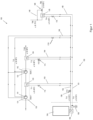
- Fig. 2 shows a compressor device 300 according to an embodiment.
- This compressor device 300 has very similar features to the compressor device 100 of Fig. 1 a compressor 30 with a first and second compressor stage 1, 2 with a first and second jacket cooler 41, 42.
- the first and second jacket cooler 41, 42 are connected in series with each other in the embodiment shown.
- an intercooler 3 and an aftercooler 4 are provided, each of which cools the compressed gas.
- the intercooler 3 cools a partially compressed compressed gas, while the aftercooler 4 cools the fully compressed compressed gas.
- An oil cooler 5 is also provided to cool oil flowing through the compressor 30.
- All the aforementioned coolers 3, 4, 5, 41 and 42 are connected to a primary cooling circuit 50, which supplies them with coolant.
- a primary heat exchanger 10 and a primary coolant pump 12 are provided.
- the primary heat exchanger 10 and/or the primary coolant pump 12 may or may not each form part of the compressor device.
- Each of the cooling elements connected to the primary cooling circuit 50 can be controlled non-manually, in particular via controllable control means, via its own, namely individual control means.
- control valves V11, V12, V13, and V16 are provided, each of which is arranged in a coolant line connected in parallel to the primary cooling circuit in order to control a coolant flow through the respective cooling element.
- control valves can be referred to simply as valves.
- the first and second jacket coolers 41 and 42 can be controlled via the control valve V13. Alternatively, separate valves would also be possible if the first and second jacket coolers 41 and 42 were connected in parallel to one another.
- the aforementioned cooling elements i.e., intercooler 3, aftercooler 4, oil cooler 5, and the first and second jacket coolers 41 and 42, can thus be controlled individually.
- jacket coolers 41 and 42 can be controlled independently of the oil cooler via valve V13.
- the cooling system can thus be controlled depending on these temperatures.
- the first and/or second jacket cooling system can be controlled as a function of the outlet temperature of the compressed gas at the outlet from the first and/or second compressor stage 1 or 2, i.e. as a function of the temperature of the compressed gas measured at the temperature measuring point T2 or T4.
- the jacket cooling systems 41 and 42 can be controlled jointly via valve V13, or individually if connected in parallel.
- the valve V13, or two corresponding valves if connected in parallel, can be referred to as the housing cooler control means. This allows the housing cooling to be controlled independently of the oil cooler. This enables targeted temperature-dependent control of the jacket cooling. This makes it possible to specifically align the control of the jacket cooling system to control the gap thickness between rotors or rotor and housing.
- the oil cooler can in turn be controlled by the V16 valve, independently of the housing cooling.
- the temperature measuring point T60 measures the oil temperature. Other temperatures can also be measured, such as the outlet temperature T100 from the compressor unit.
- all of these temperatures can be included in the cooling control and thus the control of control valves V10 to V13, V16, and V19. However, it is not necessary to consider all temperatures. Preferably, at least one temperature is considered.
- the compressor device according to Figure 2 thus has a compressed air intercooler 3, a compressed air aftercooler 4, oil cooler 5 and compressor stages 1, 2 with jacket cooling 41, 42.
- cooling water circuit 50 which has a heat exchanger 10, e.g. for heat recovery.
- the heat exchanger 10 can be used for Waste heat recovery can be used, but a cooling system that is not used for waste heat recovery can also be used. However, the benefits are particularly great when combined with waste heat recovery.
- a secondary cooling circuit 580 is provided, which is intended to cool the entire coolant flow of the primary cooling circuit 50.
- a connection via the primary-secondary heat exchanger 9 is provided.
- the secondary cooling circuit 580 can release heat via a secondary heat exchanger 11 and its coolant flow can be driven by a secondary coolant pump 13.
- the secondary cooling circuit 580 can cool a coolant flow, in particular the total coolant flow, of the primary cooling circuit, and the primary-secondary heat exchanger 9 is provided for this purpose.
- the control valve V10 is also provided for control, which is thus arranged in a coolant line of the primary-secondary heat exchanger 9.
- the control valve V10 can be controlled depending on a run-on temperature of the coolant leaving the primary-secondary heat exchanger 9.
- a temperature measuring point T10 is provided for this purpose. The temperature of the coolant flowing through the control valve V10 can be measured at the temperature measuring point T24.
- Heat exchanger 9 is used when the water inlet temperature T9 into the compressor is too high, so that the heat exchangers cannot sufficiently cool the compressor, e.g., the oil. Then, the inflowing water can be cooled via heat exchanger 9 to a desired, sufficiently low temperature T10.
- Heat exchanger 9 is particularly recommended for use when the water inlet temperature at temperature measuring point T9 in the compressor is too high, so that the heat exchangers cannot adequately cool the compressor, e.g., the oil. Then, the inflowing water can be cooled via heat exchanger 9 to a desired, sufficiently low temperature T10.
- the water volume flow through components 3, 4, 5, 1, 2 and 41, 42 can be individually and optimally adjusted using the four control valves V11, V12, V13 and V16.
- the (mixed) water outlet temperature T14 of the compressor can be controlled via the above-mentioned valves V11, V12, V13, V16.
- temperatures after the first and second compressor stage thus according to the figures at the measuring points T11 and T12, be included in order to exclude the formation of vapor lock and the associated hazards.
- At least one oil temperature e.g., at measuring point T60
- a component temperature e.g., a bearing outer ring temperature
- a high coolant temperature can be achieved at the cooling circuit outlet, namely at the outlet to heat exchanger 10 and thus at temperature measuring point T14.
- a temperature of 85-95°C, in particular 90°C to 95°C, can be achieved.
- This can be achieved by connecting the first and second pressure gas coolers 3 and 4 in series with the jacket coolers 41, 42 and the oil cooler 5.
- the first and second pressure gas coolers 3 and 4 thus receive coolant at a temperature higher than temperature T10, so that they can further heat the already preheated coolant.
- the design of the Fig. 2 provides a primary bypass control valve V19, which for simplicity can also be referred to as bypass valve V19, and via which a portion of the total coolant flow of the primary cooling circuit 50 can be fed to the intercooler 3 and aftercooler 4 before the tap - according to one embodiment also after the tap - through the first and second jacket coolers 1, 2 and the oil cooler 5.
- a series connection of the oil cooler 5 and the first and second jacket coolers 41, 42 with the two pressure gas coolers, i.e. the intercooler 3 and the aftercooler 4, is provided.
- the two pressure gas coolers thus receive heated coolant from the oil cooler 5 and the first and second jacket coolers 41, 42.
- cooler coolant which has not yet passed through the oil cooler 5 and the first and second jacket coolers 41, 42, can be fed to the two pressure gas coolers through the valve V19, whereby the volume flow to the oil cooler can be reduced. This can be used especially during a cold start, as explained below.
- the series connection of the oil cooler 5 and the first and second jacket coolers 41, 42 with the two pressure gas coolers, i.e., the intercooler 3 and the aftercooler 4, is proposed as an optimized configuration for waste heat utilization at a high temperature level.
- the oil cooler 5 and the jacket coolers 41, 42 receive a maximum volume flow with primary water that has not yet been preheated and is still at temperature T10.
- the primary bypass control valve V19 is used primarily during cold starts. When the oil has not yet reached operating temperature, the primary bypass control valve V19 is open. When the coolant is still cold, i.e., cold water, particularly with low temperatures at temperature measuring points T10, T13, and T15, the control valve V13 can also be closed. However, it has been recognized that valves V11 and V12 should control a sufficient water flow very quickly after a cold start. Therefore, it is recommended that valve V19 be opened during a cold start. During operation, once the cold start process is complete, it is recommended that bypass valve V19 be closed again slightly to allow a relatively high cooling water flow rate to the oil cooler and jacket cooling system.
- a specified water outlet temperature, i.e., the target temperature, at measuring point T14 can only be achieved by mixing the partial coolant flows at temperatures T11 and T12. Higher outlet temperatures can be achieved with these two coolers. This allows a particularly high outlet temperature T14 to be achieved.
- the waste heat from the oil cooler and jacket cooling can be made available for waste heat utilization, even at water temperatures, i.e. coolant temperatures, where this was not previously possible.
- a higher target temperature for the outlet temperature T14 can be achieved because only the partial coolants with temperatures T11 and T12, or at the measuring points T11 and T12, are mixed, resulting in a mixed temperature that is not reduced by coolants with temperatures T16 and T15. Temperatures of 85-95°C, especially 90°C to 95°C, can be achieved as the outlet temperature T14 of the coolant of the primary cooling circuit.
- Coolers 3, 4, and 5 and the jacket cooling of stages 1 and 2 are located in the primary circuit 50. Initially, the oil cooler 5 and the jacket cooling of stages 1 and 2 are connected in parallel. The intercooler 3 and the aftercooler 4 are then connected in series. These are also connected in parallel.
- the secondary circuit 580 cools the primary circuit 50 as needed.
- This wiring variant offers particular advantages in heat recovery via the heat exchanger 10, which can also be referred to as waste heat utilization.
- a regulation to a higher water outlet temperature T14 i.e. the possibility of specifying a higher setpoint for this water outlet temperature T14, namely higher than before, is possible, e.g. 90°C...95°C instead of -80° or 85°C, as before.
- the user can specify a water outlet temperature T14.
- the oil cooler only receives as much water as necessary to achieve the optimal oil temperature.
- the following Figure 3 describes another embodiment, but for the sake of clarity, partially identical reference numerals are used to the embodiment of the Fig. 2 used to better demonstrate relationships. However, it is not necessary for the elements to be identical.
- Fig. 3 shows an embodiment of a compressor device 300, which provides a jacket cooler heat exchanger 6 for the first and second jacket coolers 41, 42.
- Jacket coolers 41, 42 can also be connected in series here.
- a coolant flow through the jacket coolers 41, 42 is driven by a jacket cooler pump 14 and thus drives a separate cooling circuit, which can be referred to as the compressor cooling circuit 32, because the coolant flows through corresponding jacket areas in the first and second compressors 1, 2.
- the jacket cooler pump 14 is thus a cooling water pump for the compressor cooling circuit 32.
- the compressor cooling circuit 32 or the coolant therein flows through the first and second jacket coolers 41, 42 and is guided through the heat exchanger 6, namely through a primary side of the jacket cooler heat exchanger 6. Coolant from the primary cooling circuit 50 flows through the secondary side of the jacket cooler heat exchanger 6.
- the corresponding coolant flow from the primary cooling circuit 50 through the jacket cooler heat exchanger 6 is controlled by the control valve V13.
- the relevant temperatures are those recorded at the temperature measuring points T9, T10, T11, T12, T14, T16, T19, T20, T23, T24, T28, T29, T31, T51, T52, T85, and T100. Additionally, the pressure dew point M85 downstream of the adsorption dryer 20 can also be recorded.
- valve V13 is controlled as a function of the temperatures of the coolant leaving the first and/or second jacket cooler 41, 42.
- Temperatures at measuring points Txx with "xx" as a placeholder for the respective number of the temperature or measuring point can also be referred to below and above for simplicity and synonymously as temperatures Txx.
- valve V13 During a cold start, valve V13 remains closed, so there is no coolant flow at T23. Therefore, the temperature at measuring point T23 does not rise.
- valve V13 is opened by the control system, which can also be described as "open-regulated.” Only then can the temperature at measuring point T23 be used for control.
- the control valve V13 can be referred to as a jacket cooler control valve, and it controls the coolant flow through the jacket cooler heat exchanger 6. In other embodiments, it can also control the coolant volume flow for the jacket coolers 41, 42.
- the valve V13 controls the temperatures of the coolant leaving the first and/or second jacket coolers 41, 42.
- Fig. 3 It also has a second and third aftercooler 7, 8, which can also be referred to as second and third compressed air aftercoolers and are specifically designed as heat exchangers here. They are arranged in a compressed gas line 34, namely downstream of the compressed gas behind the aftercooler 4 or compressed gas aftercooler 4. This allows for additional cooling of the compressed gas.
- the third compressed air aftercooler or compressed gas aftercooler can also be synonymously referred to as a dryer aftercooler.
- Fig. 3 shows the use of a dryer for the compressed gas, in particular an adsorption dryer 20, which is integrated into the compressed gas line 34.
- a dryer for the compressed gas in particular an adsorption dryer 20, which is integrated into the compressed gas line 34.
- an additional aftercooler 7 also makes sense in order to regulate the dew point and the outlet temperature.
- the third compressed air aftercooler 8 makes less sense with the refrigeration dryer as shown.
- the refrigeration dryer the third compressed air aftercooler 8 could rather be used to heat the compressed air. Therefore, the use of an adsorption dryer is particularly suggested here.
- the third compressed air aftercooler 8 is used specifically to cool the compressed air.
- the compressed gas dryer 20 is arranged behind the second aftercooler 7 and before the third aftercooler 8 in the flow direction of the compressed gas.
- a control valve V25 and V28, respectively, is provided to control the coolant flow through both the second aftercooler 7 and the third aftercooler 8. Thus, even the second and third aftercoolers 7, 8 can be controlled independently of each other.
- a temperature measuring point T25 or T28 is provided and assigned to the second or third aftercooler 7, 8 and thus to the corresponding control valve V25 or V28.
- the second aftercooler 7 can support the dryer and thus influence the pressure dew point after the dryer. However, this also reduces the outlet temperature from the dryer, which is sometimes desirable, but sometimes undesirable.
- the heat exchanger, or aftercooler, downstream of the dryer allows the compressed air to be brought to the optimal temperature for downstream applications.
- the air at the outlet can be significantly warmer than at the inlet, so additional cooling may be necessary.
- Control valve V25 which controls the coolant flow through the second aftercooler 7, can control this coolant flow depending on the temperature measured by temperature measuring point T25. Preferably, however, valve V25 is used to control the air outlet temperature T52.
- the setpoint for this temperature T52 is determined by a control cascade from the desired pressure dew point downstream of the dryer. In systems without a dryer, the setpoint for temperature T52 is determined from the setpoint for temperature T100, which can be specified externally.
- control according to the temperature T25 or according to a temperature difference T25-T20 is also possible.
- the control valve V25 controls the coolant flow depending on the outlet temperature of the compressed air at the temperature measuring point T52 from the second aftercooler 7.
- control valve V28 which controls the coolant flow through the third aftercooler 8, regulates the compressed air outlet temperature T100. Control based on the temperature T28 or the differential temperature T28-T20 is provided according to an alternative embodiment.
- a secondary cooling circuit 580 cools a coolant flow, in particular the total coolant flow, of the primary cooling circuit 50, and a corresponding primary-secondary heat exchanger 9 is provided for this purpose.
- the control valve V10 is also provided for control, which is thus arranged in a coolant line, and thus also in a coolant flow, namely in the secondary cooling circuit of the primary-secondary heat exchanger 9.
- the control valve V10 can be controlled depending on a run-on temperature of the coolant leaving the primary-secondary heat exchanger 9.
- a temperature measuring point T10 is provided for this purpose. The temperature of the coolant flowing through the control valve V10 can be detected at the temperature measuring point T24.
- a primary circuit bypass 21 can be provided, via which part of the total coolant flow of the primary cooling circuit 50 flows past the primary heat exchanger 10.
- the internal pump 12b in conjunction with the bypass 21 and the heat exchanger 9, can maintain the operation of the compressor and thus the compressed air supply, even if the external heat sink 10 and/or the pump 12a are not available. This can be the case, for example, during maintenance work or conversion measures, or even in the case of seasonal heat requirements.
- the external pump 12a is specifically designed to compensate for external pressure losses, namely in the heat exchanger 10 and in the piping and possibly other elements.
- the internal pump 12b can run as a backup or standby only when needed. It only switches on when the primary coolant pump 12a is delivering no or too little water, which would otherwise cause the compressor to overheat and shut down.
- a pressure dew point temperature measuring point M85 is provided downstream of the drying device 20.
- the pressure dew point temperature is determined at this point, and the cooling can be controlled based on this.
- the valve V25 has a great effect here if the additional aftercooler 7 is present.
- the dew point M85 can be improved by using valve V11 (opening less to increase the temperature T31) and valve V12 (opening more to reduce the temperature T51).
- a higher temperature T31 results in a higher regeneration temperature for the dryer, so that a lower dew point M85 can be achieved.
- valve V25 has the greatest effect when the additional aftercooler 7 is present. Furthermore, the dew point M85 can be improved by opening valve V11 less to increase the temperature T31, and by opening valve V12 more to reduce the temperature T51.
- the pressure dew point downstream of the dryer is particularly relevant. At the dryer inlet, the compressed air is usually 100% saturated. Therefore, the temperature and pressure dew point here are almost identical, provided the condensate has been separated and drained as completely as possible upstream of the dryer.
- the temperature of the compressed gas at the inlet to the dryer is particularly important for the drying result.
- the compressor should be designed to separate the condensate that has already formed.
- the embodiment according to Fig. 3 is designed so that the second aftercooler 7 and third aftercooler 8 are connected in parallel to the primary cooling circuit 50.
- a secondary cooling circuit 580 is also provided, which, as in Fig. 2 and is coupled to the primary cooling circuit 50.
- the intercooler 3 and aftercooler 4 which can also be referred to synonymously as first aftercooler 4 in this and the other embodiments, are, similar to the embodiment of the Fig. 2 , not connected in parallel to the primary cooling circuit 50, but in series, in which the coolant is supplied to them from the primary cooling circuit 50 after it has flowed through the other coolers.
- a primary bypass control valve V19 as in Fig. 2 shown, is unnecessary here, since a sufficient water volume flow always flows through the second aftercooler 7 together with the control valve V25, so that the intercooler 3 and the aftercooler 4 connected in series can always receive a sufficient volume flow. However, it is shown as a precautionary measure as a possible alternative.
- This primary bypass control valve V19 could be used if the valve V28 is closed because the temperature T100 is sufficiently low and the valve V25 is closed because the pressure dew point M85 is sufficiently low. In this case, the valve V19 must open, so that in particular the heat exchanger 3 after the compressor or compressor stage 1 receives more and cooler water, as this improves the compression efficiency.
- the primary bypass control valve V19 can ensure that a portion of the coolant that has not flowed through the third aftercooler 8 is supplied to the intercooler 3 and aftercooler 4. It is also provided that the intercooler 3 and the aftercooler 4 are arranged in series in the primary cooling circuit or are interconnected, but are connected in parallel to each other. This series connection allows a higher cooling water temperature to be achieved by the intercoolers 3 and aftercoolers 4; in particular, the cooling water outlet temperature at T14 can be particularly high at the outlet of the primary cooling circuit 50.
- the intercooler 3 and the aftercooler 4 are connected in series with the primary cooling circuit, whereby, for the sake of simplicity, the primary bypass control valve V19 is ignored for the following explanation.
- the intercooler 3 and the aftercooler 4 thus jointly receive the complete coolant flow, i.e., the total coolant flow of the primary cooling circuit 50, which has already flowed through a cooler and is therefore heated above temperature T10, as this is due to the series connection.
- the intercooler 3 and the aftercooler 4 can discharge a coolant at a comparatively high temperature.
- a very high water outlet temperature T14 is possible, especially up to about ⁇ 95°C.
- Adequate jacket cooling and oil cooling with heating water at high volume flow is possible, especially via the primary water system with inlet and outlet temperatures T10 and T14, respectively.
- a sufficient dew point can be achieved because the aftercooler 7 receives a large volume flow of cool heating water.
- the control valve V13 and a jacket cooling pump 14 are provided to control the compressor cooling circuit 32, which can also be referred to as the jacket cooling circuit. These represent a possible variant for the jacket cooling circuit.
- FIG. 3 The temperatures T2 and T4 are shown. Both can reach, for example, 180°C. This should illustrate that the high water outlet temperatures T11, T12 and T14 of, for example, 90°C can be easily achieved, which is comparable to the temperatures T16 and T23 shown in Figure 1 shown is not possible.
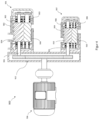
- FIG. 4 shows a compressor 900 with a first and a second compressor stage 901 and 907 in a schematic, partially sectioned view.
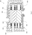
- Figure 5 a first compressor stage 901 in an enlarged view. The following refers to the Figure 4 Reference is made to the first compressor stage, insofar as it is explained, Figure 5 reference is made.
- the Figure 4 thus shows a dry-running screw compressor, which essentially forms the compressor 900.
- the first compressor stage 901 thus performs a first-stage compression during operation.
- the first compressor stage 901 has a housing 902 and coolant channels 903 of a jacket cooling, which are particularly useful in Figure 5 are presented more clearly.
- Compressor screws 904 are provided to compress the compressed gas, particularly compressed air, and mesh with each other for compression. They are driven by a drive shaft 905 of the corresponding compressor stage.
- the second compressor stage 907 which further compresses the gas, particularly compressed air, compressed in the first compressor stage, has a housing 909 with coolant channels 908 and compressor screws 910, which are driven by a drive shaft 911.
- Both drive shafts 905 and 911 are driven by a common drive motor 906, and for this purpose a gearbox 912 is provided which distributes the drive power from the drive motor to the two drive shafts 905 and 911 in order to thereby drive the compressor screws 904 and 910.
- the two compressor stages 901 and 907 can be cooled via the jacket cooling, which is realized with the help of the coolant channels 903 and 908.
- a cooling medium in particular cooling water, flows through these coolant channels 903 and 908, and this can be controlled together or individually.
Landscapes
- Engineering & Computer Science (AREA)
- General Engineering & Computer Science (AREA)
- Mechanical Engineering (AREA)
- Applications Or Details Of Rotary Compressors (AREA)
- Compressors, Vaccum Pumps And Other Relevant Systems (AREA)
Applications Claiming Priority (1)
| Application Number | Priority Date | Filing Date | Title |
|---|---|---|---|
| DE102023135011.0A DE102023135011A1 (de) | 2023-12-13 | 2023-12-13 | Kompressoreinrichtung mit Kühlung und Verfahren zum Betreiben einer Kompressoreinrichtung |
Publications (2)
| Publication Number | Publication Date |
|---|---|
| EP4571114A2 true EP4571114A2 (fr) | 2025-06-18 |
| EP4571114A3 EP4571114A3 (fr) | 2025-08-20 |
Family
ID=93843268
Family Applications (1)
| Application Number | Title | Priority Date | Filing Date |
|---|---|---|---|
| EP24218453.9A Pending EP4571114A3 (fr) | 2023-12-13 | 2024-12-09 | Système de compresseur avec refroidissement et procédé de fonctionnement d'un système de compresseur |
Country Status (6)
| Country | Link |
|---|---|
| US (1) | US20250198409A1 (fr) |
| EP (1) | EP4571114A3 (fr) |
| JP (1) | JP2025094930A (fr) |
| CN (1) | CN120140227A (fr) |
| DE (1) | DE102023135011A1 (fr) |
| MX (1) | MX2024015289A (fr) |
Families Citing this family (1)
| Publication number | Priority date | Publication date | Assignee | Title |
|---|---|---|---|---|
| DE102023135013A1 (de) * | 2023-12-13 | 2025-06-18 | Kaeser Kompressoren Se | Kompressoreinrichtung mit Kühlung und Verfahren zum Betreiben einer Kompressoreinrichtung |
Citations (1)
| Publication number | Priority date | Publication date | Assignee | Title |
|---|---|---|---|---|
| WO2022163079A1 (fr) | 2021-01-26 | 2022-08-04 | 株式会社日立産機システム | Compresseur de gaz |
Family Cites Families (12)
| Publication number | Priority date | Publication date | Assignee | Title |
|---|---|---|---|---|
| FR1475778A (fr) * | 1966-02-03 | 1967-04-07 | Perfectionnements apportés aux moteurs diesel suralimentés | |
| DE2849286A1 (de) * | 1978-11-14 | 1980-05-29 | Bruno Kuemmerle | Kuehlvorrichtung fuer fluessige schmier-, arbeits- und/oder kuehlmittel, insbesondere fuer werkzeugmaschinen |
| DE4104093A1 (de) * | 1991-02-11 | 1992-08-13 | Behr Gmbh & Co | Kuehlanlage fuer ein fahrzeug mit verbrennungsmotor |
| JPH09158870A (ja) * | 1995-12-07 | 1997-06-17 | Hitachi Ltd | 水冷式二段オイルフリースクリュー圧縮機 |
| DE10065003A1 (de) * | 2000-12-23 | 2002-07-04 | Bosch Gmbh Robert | Kühlsystem für ein Kraftfahrzeug |
| DE10117790A1 (de) * | 2001-04-10 | 2002-10-17 | Boge Kompressoren | Kompressoranlage und Verfahren zum Betreiben einer Kompressoranlage |
| DE10156179A1 (de) * | 2001-11-15 | 2003-05-28 | Leybold Vakuum Gmbh | Kühlung einer Schraubenvakuumpumpe |
| JP5495293B2 (ja) * | 2009-07-06 | 2014-05-21 | 株式会社日立産機システム | 圧縮機 |
| WO2013119483A1 (fr) * | 2012-02-07 | 2013-08-15 | Johnson Controls Technology Company | Refroidissement et commande de moteur hermétique |
| EP3628868B1 (fr) * | 2017-03-07 | 2021-02-24 | ATLAS COPCO AIRPOWER, naamloze vennootschap | Module de compresseur de compression de gaz et compresseur en étant équipé |
| WO2020195528A1 (fr) * | 2019-03-27 | 2020-10-01 | 株式会社日立産機システム | Système de compresseur, et procédé de commande pour celui-ci |
| DE102021121424A1 (de) * | 2021-08-18 | 2023-02-23 | Zf Cv Systems Global Gmbh | Mehrstufiger, elektrisch antreibbarer Kompressor |
-
2023
- 2023-12-13 DE DE102023135011.0A patent/DE102023135011A1/de active Pending
-
2024
- 2024-12-09 EP EP24218453.9A patent/EP4571114A3/fr active Pending
- 2024-12-10 MX MX2024015289A patent/MX2024015289A/es unknown
- 2024-12-12 JP JP2024217529A patent/JP2025094930A/ja active Pending
- 2024-12-13 US US18/980,794 patent/US20250198409A1/en active Pending
- 2024-12-13 CN CN202411840375.9A patent/CN120140227A/zh active Pending
Patent Citations (1)
| Publication number | Priority date | Publication date | Assignee | Title |
|---|---|---|---|---|
| WO2022163079A1 (fr) | 2021-01-26 | 2022-08-04 | 株式会社日立産機システム | Compresseur de gaz |
Also Published As
| Publication number | Publication date |
|---|---|
| JP2025094930A (ja) | 2025-06-25 |
| CN120140227A (zh) | 2025-06-13 |
| EP4571114A3 (fr) | 2025-08-20 |
| DE102023135011A1 (de) | 2025-06-18 |
| US20250198409A1 (en) | 2025-06-19 |
| MX2024015289A (es) | 2025-07-01 |
Similar Documents
| Publication | Publication Date | Title |
|---|---|---|
| EP1606564B1 (fr) | Procede et dispositif de recuperation d'energie | |
| DE60310216T2 (de) | Klimaanlage | |
| EP1329381A1 (fr) | Système de déshumidification pour climatisation à cycle d'air | |
| EP1512855A1 (fr) | générateur électrique et son procédé d'opération | |
| EP1451031A1 (fr) | Installation de climatisation avec transmetteur de chaleur auxiliaire monte dans le circuit de refrigerant | |
| DE102011017433A1 (de) | Verfahren zur intelligenten Regelung einer Kompressoranlage mit einer Wärmerückgewinnung | |
| EP3417213B1 (fr) | Appareil de froid pourvu d'une pluralité de compartiments de stockage | |
| EP2261503A1 (fr) | Eolienne | |
| DE3444057A1 (de) | Klimaanlage mit luftumwaelzung | |
| DE102015202829A1 (de) | Druckluftspeicherkraftwerk sowie Verfahren zum Betreiben eines Druckluftspeicherkraftwerks | |
| DE3301303C2 (fr) | ||
| CH698244B1 (de) | Zweitakt-Grossdieselmotor mit mehreren variablen Turboladern. | |
| EP3388677B1 (fr) | Procédé de commande d'un compresseur à vis | |
| EP4571114A2 (fr) | Système de compresseur avec refroidissement et procédé de fonctionnement d'un système de compresseur | |
| EP3397843A1 (fr) | Turbine à gaz équipée d'un piston à poussée axiale et d'un palier radial | |
| DE102017115903A1 (de) | Wärmepumpenanlage mit hydraulischem Temperaturstellglied zur Erhöhung der Last | |
| DE10323287A1 (de) | Verfahren und Vorrichtung zur Energierückgewinnung | |
| DE69514936T2 (de) | Kühlsystem und verfahren | |
| DE632316C (de) | Gasturbinenanlage mit Gleichdruckverbrennung | |
| DE102013102879A1 (de) | Kompressor und Verfahren zum Betreiben eines Kompressors | |
| DE102004040890A1 (de) | Kraftwerksanlage, und Verfahren zum Betrieb | |
| EP2602571A1 (fr) | Dispositif de pompe à chaleur réversible et son procédé de fonctionnement | |
| DE102016123277A1 (de) | Kälteanlage und Verfahren zur Regelung einer Kälteanlage | |
| DE102023135013A1 (de) | Kompressoreinrichtung mit Kühlung und Verfahren zum Betreiben einer Kompressoreinrichtung | |
| EP3714962B1 (fr) | Station d'aire comprimé |
Legal Events
| Date | Code | Title | Description |
|---|---|---|---|
| PUAI | Public reference made under article 153(3) epc to a published international application that has entered the european phase |
Free format text: ORIGINAL CODE: 0009012 |
|
| STAA | Information on the status of an ep patent application or granted ep patent |
Free format text: STATUS: THE APPLICATION HAS BEEN PUBLISHED |
|
| AK | Designated contracting states |
Kind code of ref document: A2 Designated state(s): AL AT BE BG CH CY CZ DE DK EE ES FI FR GB GR HR HU IE IS IT LI LT LU LV MC ME MK MT NL NO PL PT RO RS SE SI SK SM TR |
|
| PUAL | Search report despatched |
Free format text: ORIGINAL CODE: 0009013 |
|
| AK | Designated contracting states |
Kind code of ref document: A3 Designated state(s): AL AT BE BG CH CY CZ DE DK EE ES FI FR GB GR HR HU IE IS IT LI LT LU LV MC ME MK MT NL NO PL PT RO RS SE SI SK SM TR |
|
| RIC1 | Information provided on ipc code assigned before grant |
Ipc: F04C 18/16 20060101AFI20250716BHEP Ipc: F04C 23/00 20060101ALI20250716BHEP Ipc: F04C 29/04 20060101ALI20250716BHEP |
|
| STAA | Information on the status of an ep patent application or granted ep patent |
Free format text: STATUS: REQUEST FOR EXAMINATION WAS MADE |
|
| 17P | Request for examination filed |
Effective date: 20260220 |