EP4571168A2 - Pièce de raccordement pour injecteur de carburant de moteur à combustion interne - Google Patents
Pièce de raccordement pour injecteur de carburant de moteur à combustion interne Download PDFInfo
- Publication number
- EP4571168A2 EP4571168A2 EP25174584.0A EP25174584A EP4571168A2 EP 4571168 A2 EP4571168 A2 EP 4571168A2 EP 25174584 A EP25174584 A EP 25174584A EP 4571168 A2 EP4571168 A2 EP 4571168A2
- Authority
- EP
- European Patent Office
- Prior art keywords
- pressure
- connecting piece
- connection
- injector
- fuel injector
- Prior art date
- Legal status (The legal status is an assumption and is not a legal conclusion. Google has not performed a legal analysis and makes no representation as to the accuracy of the status listed.)
- Pending
Links
Images

Classifications
-
- F—MECHANICAL ENGINEERING; LIGHTING; HEATING; WEAPONS; BLASTING
- F02—COMBUSTION ENGINES; HOT-GAS OR COMBUSTION-PRODUCT ENGINE PLANTS
- F02M—SUPPLYING COMBUSTION ENGINES IN GENERAL WITH COMBUSTIBLE MIXTURES OR CONSTITUENTS THEREOF
- F02M55/00—Fuel-injection apparatus characterised by their fuel conduits or their venting means; Arrangements of conduits between fuel tank and pump F02M37/00
- F02M55/02—Conduits between injection pumps and injectors, e.g. conduits between pump and common-rail or conduits between common-rail and injectors
- F02M55/025—Common rails
-
- F—MECHANICAL ENGINEERING; LIGHTING; HEATING; WEAPONS; BLASTING
- F02—COMBUSTION ENGINES; HOT-GAS OR COMBUSTION-PRODUCT ENGINE PLANTS
- F02M—SUPPLYING COMBUSTION ENGINES IN GENERAL WITH COMBUSTIBLE MIXTURES OR CONSTITUENTS THEREOF
- F02M61/00—Fuel-injectors not provided for in groups F02M39/00 - F02M57/00 or F02M67/00
- F02M61/16—Details not provided for in, or of interest apart from, the apparatus of groups F02M61/02 - F02M61/14
- F02M61/165—Filtering elements specially adapted in fuel inlets to injector
-
- F—MECHANICAL ENGINEERING; LIGHTING; HEATING; WEAPONS; BLASTING
- F15—FLUID-PRESSURE ACTUATORS; HYDRAULICS OR PNEUMATICS IN GENERAL
- F15B—SYSTEMS ACTING BY MEANS OF FLUIDS IN GENERAL; FLUID-PRESSURE ACTUATORS, e.g. SERVOMOTORS; DETAILS OF FLUID-PRESSURE SYSTEMS, NOT OTHERWISE PROVIDED FOR
- F15B1/00—Installations or systems with accumulators; Supply reservoir or sump assemblies
- F15B1/02—Installations or systems with accumulators
- F15B1/04—Accumulators
-
- F—MECHANICAL ENGINEERING; LIGHTING; HEATING; WEAPONS; BLASTING
- F16—ENGINEERING ELEMENTS AND UNITS; GENERAL MEASURES FOR PRODUCING AND MAINTAINING EFFECTIVE FUNCTIONING OF MACHINES OR INSTALLATIONS; THERMAL INSULATION IN GENERAL
- F16L—PIPES; JOINTS OR FITTINGS FOR PIPES; SUPPORTS FOR PIPES, CABLES OR PROTECTIVE TUBING; MEANS FOR THERMAL INSULATION IN GENERAL
- F16L41/00—Branching pipes; Joining pipes to walls
- F16L41/02—Branch units, e.g. made in one piece, welded, riveted
- F16L41/021—T- or cross-pieces
-
- F—MECHANICAL ENGINEERING; LIGHTING; HEATING; WEAPONS; BLASTING
- F16—ENGINEERING ELEMENTS AND UNITS; GENERAL MEASURES FOR PRODUCING AND MAINTAINING EFFECTIVE FUNCTIONING OF MACHINES OR INSTALLATIONS; THERMAL INSULATION IN GENERAL
- F16L—PIPES; JOINTS OR FITTINGS FOR PIPES; SUPPORTS FOR PIPES, CABLES OR PROTECTIVE TUBING; MEANS FOR THERMAL INSULATION IN GENERAL
- F16L55/00—Devices or appurtenances for use in, or in connection with, pipes or pipe systems
- F16L55/02—Energy absorbers; Noise absorbers
- F16L55/027—Throttle passages
-
- F—MECHANICAL ENGINEERING; LIGHTING; HEATING; WEAPONS; BLASTING
- F16—ENGINEERING ELEMENTS AND UNITS; GENERAL MEASURES FOR PRODUCING AND MAINTAINING EFFECTIVE FUNCTIONING OF MACHINES OR INSTALLATIONS; THERMAL INSULATION IN GENERAL
- F16L—PIPES; JOINTS OR FITTINGS FOR PIPES; SUPPORTS FOR PIPES, CABLES OR PROTECTIVE TUBING; MEANS FOR THERMAL INSULATION IN GENERAL
- F16L55/00—Devices or appurtenances for use in, or in connection with, pipes or pipe systems
- F16L55/04—Devices damping pulsations or vibrations in fluids
- F16L55/045—Devices damping pulsations or vibrations in fluids specially adapted to prevent or minimise the effects of water hammer
- F16L55/05—Buffers therefor
-
- F—MECHANICAL ENGINEERING; LIGHTING; HEATING; WEAPONS; BLASTING
- F02—COMBUSTION ENGINES; HOT-GAS OR COMBUSTION-PRODUCT ENGINE PLANTS
- F02M—SUPPLYING COMBUSTION ENGINES IN GENERAL WITH COMBUSTIBLE MIXTURES OR CONSTITUENTS THEREOF
- F02M2200/00—Details of fuel-injection apparatus, not otherwise provided for
- F02M2200/28—Details of throttles in fuel-injection apparatus
-
- F—MECHANICAL ENGINEERING; LIGHTING; HEATING; WEAPONS; BLASTING
- F02—COMBUSTION ENGINES; HOT-GAS OR COMBUSTION-PRODUCT ENGINE PLANTS
- F02M—SUPPLYING COMBUSTION ENGINES IN GENERAL WITH COMBUSTIBLE MIXTURES OR CONSTITUENTS THEREOF
- F02M2200/00—Details of fuel-injection apparatus, not otherwise provided for
- F02M2200/40—Fuel-injection apparatus with fuel accumulators, e.g. a fuel injector having an integrated fuel accumulator
-
- F—MECHANICAL ENGINEERING; LIGHTING; HEATING; WEAPONS; BLASTING
- F02—COMBUSTION ENGINES; HOT-GAS OR COMBUSTION-PRODUCT ENGINE PLANTS
- F02M—SUPPLYING COMBUSTION ENGINES IN GENERAL WITH COMBUSTIBLE MIXTURES OR CONSTITUENTS THEREOF
- F02M2200/00—Details of fuel-injection apparatus, not otherwise provided for
- F02M2200/85—Mounting of fuel injection apparatus
Definitions
- the invention relates to a connector for a fuel injector of an internal combustion engine.
- Such connectors provide at least one high-pressure inlet connection and at least one high-pressure outlet connection.
- the fuel is brought to the required pressure level by a central high-pressure pump.
- the pressurized fuel is distributed to the individual fuel injectors via a common piping system.
- a piping system with parallel or series connection of the individual injectors Two options for fuel distribution emerge: a piping system with parallel or series connection of the individual injectors.
- the individual injectors are connected in parallel to a common distribution pipe of the high-pressure line.
- the second variant involves supplying the fuel from a high-pressure pump to a first injector, from which the fuel is forwarded to the subsequent injector.
- each injector must have at least two high-pressure connections, one of which serves as an inlet and one as an outlet.
- the generic connector is suitable for constructing a series connection of a plurality of fuel injectors.
- One connection serves as the high-pressure input connection, and at least one second connection serves as the high-pressure output connection.
- the connecting piece for the high-pressure connections, ie the at least one high-pressure inlet connection and the at least one high-pressure outlet connection, via which the respective connections open separately from one another within an internal high-pressure reservoir.
- the essential point here is that the connections, ie the at least one high-pressure inlet connection and the at least one high-pressure outlet connection are only indirectly fluidically connected to each other via the internal high-pressure accumulator.
- any pressure pulsations within the high-pressure lines can be eliminated or sufficiently dampened, so that the transmission of these fluctuations from a first injector in the series circuit to at least one downstream injector is prevented or at least reduced.
- an existing high-pressure accumulator could also be used within a connected injector, into which the high-pressure channels of the connector open separately from one another.
- the high-pressure channels are routed separately to the interface between the connector and the injector, where they then open separately into the injector's internal high-pressure accumulator.
- a throttle is additionally installed in the high-pressure supply channel from the high-pressure inlet connection to the internal high-pressure accumulator.
- the same can also be provided in the high-pressure supply channel from the high-pressure outlet connection to the high-pressure accumulator.
- a throttle is provided in only one of the two high-pressure supply channels; however, a design with an integrated throttle in both high-pressure supply channels is preferred.
- the aforementioned pressure pulsations within the high-pressure lines can be dampened even more.
- a throttle can be implemented by a defined diameter reduction of the respective high-pressure supply channel. A diameter reduction toward the high-pressure accumulator is advantageous.
- the structural design of the connecting piece or its specific shape is generally not restricted. However, a symmetrical, particularly axially symmetrical, design of the connecting piece proves advantageous.
- a conceivable design is a T-shaped connector or T-piece, with the high-pressure inlet and outlet connections formed at the head of the T-piece.
- the base of the T-shaped connector forms the interface to the injector.
- the internal high-pressure accumulator can be formed within the T-piece as a longitudinal bore extending toward the base of the T-piece. Ideally, the high-pressure supply channels open at right angles to the longitudinal axis of the bore of the high-pressure accumulator.
- connection of external high-pressure lines to the high-pressure inlet or high-pressure outlet connection can be detachable.
- the high-pressure inlet and/or high-pressure outlet connection includes a thread for screwing in an external high-pressure line. This is particularly preferred as an external thread located on the outside of the high-pressure inlet or high-pressure outlet connection.
- connection piece can also be mounted to the injector using a detachable connection.
- a screw connection between the connection piece and the injector housing proves advantageous, particularly using one or more clamping nuts.
- the connection piece does not necessarily have to be a component that can be separated from the injector or injector housing.
- the connection piece does not necessarily have to be a component that can be separated from the injector or injector housing.
- the connection piece does not necessarily have to be an integral part of the injector housing, i.e., to be formed by a section of the injector/injector housing.
- injector/injector housing and the connection piece to be formed from a one-piece base component. The interface mentioned above is then only a theoretical interface between the two areas of the unified component.
- the connecting piece provides at least one internal filter which ensures the fluid connection between the internal high-pressure accumulator of the connecting piece and the injector receiving the connecting piece.
- a corresponding filter housing is provided for this purpose, which serves to receive the filter, wherein the filter housing forms the corresponding connection interface of the internal high-pressure accumulator with an injector.
- the present invention also relates to a fuel injector with at least one connecting piece according to the present invention.
- the fuel injector has the same advantages and properties as have already been explained above with reference to the connecting piece.
- a corresponding injector also comprises an embodiment in which the internal high-pressure accumulator for connecting the high-pressure inlet and/or high-pressure outlet connection is partially or completely integrated within the fuel injector housing.
- the high-pressure supply channels of the connecting piece end separately from one another at the interface to the injector.
- the injector has further channels in its corresponding interface region, whereby the high-pressure supply channels can ultimately open separately from one another into the internal high-pressure accumulator of the injector.
- the invention also relates to an injection system with a plurality of injectors according to the present invention, which are connected to one another in series via their connecting pieces.
- the invention also relates to a work machine with an internal combustion engine and an injection system according to the present invention. Accordingly, the same advantages and properties as already described in the context of the connection piece according to the invention result for both the injection system and the work machine.
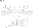
- the sectional view of the Figure 1 shows the axially symmetrical, T-shaped connecting piece 10, which is connected to the injector housing 20 at the base by means of a screw connection.
- the connections for high-pressure lines A, B are formed on opposite sides of the head area of the connecting piece 10.
- the high-pressure line A is connected to the high-pressure inlet connection by screwing the union nut 30 to the external thread 13A provided on the connecting flange. This presses the high-pressure line A axially into the opening of the high-pressure inlet connection.
- the high-pressure line B which is also screwed to the external thread 13B provided on the high-pressure outlet connection by means of a union nut 30.
- An individual high-pressure supply channel 11A, 11B extends from each of the two high-pressure connections, running in the axial connection direction from the high-pressure inlet or high-pressure outlet connection to an internal high-pressure accumulator 15 and discharging into it.
- the high-pressure accumulator 15 extends transversely to the direction of the supply channels 11A, 11B, i.e., in the vertical direction to the base of the connecting piece 10.
- Both the high-pressure supply channel 11A and the high-pressure supply channel 11B each provide an integrated throttle 12A, 12B, which is characterized by a tapering of the channel diameter of the respective high-pressure supply channel 11A, 11B toward the integrated high-pressure accumulator 15.
- both throttles 12A, 12B open directly into the integrated pressure accumulator 15; theoretically, however, the throttles 12A, 12B could be located in a more central section of the high-pressure supply channel 11A, 11B.
- high-pressure line A is only indirectly connected to the outgoing high-pressure line B via the integrated high-pressure accumulator 15 ensures that the pressure oscillations caused by a central high-pressure pump are eliminated or at least significantly dampened and cannot be transmitted to another connected injector via the high-pressure channel 11B or the high-pressure line B.
- the integrated throttles 12A, 12B contribute to further eliminating or dampening the pressure waves caused by the pump.
- the design of the Figure 2 shows a slightly modified variant of the connecting piece 10, which differs from the variant of the Figure 1 only differs in that the Figure 1
- the throttles 12A, 12B contained therein have been omitted, so that the diameter of the high-pressure supply channels 11A, 11B remains constant along its length.
- only the pressure accumulator 15 ensures sufficient elimination or damping of any pressure pulsations in the high-pressure line A.
- the fluid interface of the connector 10 with the injector 20 is formed via the integrated filter 17, which is accommodated in a filter housing 16.
- the filter housing 16 is inserted into the opening of the high-pressure accumulator 15 facing the interface.
- the filter housing 16 is flush with the opening of the high-pressure accumulator 15, while the filter element 17 protrudes a short distance from the opening.
- the high-pressure accumulator 21 of the injector has a different diameter than the high-pressure accumulator 15 of the connecting piece 10, at least with respect to its opening diameter.
- the connecting piece 10 and the injector 20 are connected to one another in such a way that the two high-pressure accumulators 15, 21, or their openings, fit together precisely.
- the protruding filter element 17 of the connecting piece 10 extends into the high-pressure accumulator 21 of the injector.
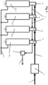
- FIG. 3 shows a schematic circuit layout of the injection system according to the invention with a total of four fuel injectors 20_1, 20_2, 20_3, 20_4, each of which carries the connector 10 according to the invention at the head end of the housing.
- the central fuel supply is designated by reference numeral 2.
- the fuel is brought to the required pressure level by means of the central high-pressure pump 4, which is then supplied to the first injector 20_1 of the series circuit via the fuel supply line 3.
- the supply line 3 is mounted on the high-pressure inlet connection of the connector 10 of the first injector 20_1.
- the fuel then flows via the high-pressure outlet connection of the connecting piece 10 to the subsequent injector 20_2 or the high-pressure inlet connection of the associated connecting piece 10.
- the outlet of the injector 20_2 is in turn connected to the inlet of the subsequent injector 20_3, from where the fuel ultimately flows to the last injector 20_4.
- the high-pressure outlet connection of the fourth and thus final fuel injector 20_4 is sealed with a suitable plug.
- an additional fuel discharge 5 can be provided in the area of the connecting pieces 10, through which any breakage leaks can be returned to the fuel tank 7.
- a corresponding sensor 6 serves to detect any breakage leaks.
- the fuel discharge 8 ensures the discharge of any switching leaks from the injectors 20_1-20_4.
Landscapes
- Engineering & Computer Science (AREA)
- General Engineering & Computer Science (AREA)
- Mechanical Engineering (AREA)
- Chemical & Material Sciences (AREA)
- Combustion & Propulsion (AREA)
- Physics & Mathematics (AREA)
- Fluid Mechanics (AREA)
- Fuel-Injection Apparatus (AREA)
Applications Claiming Priority (3)
| Application Number | Priority Date | Filing Date | Title |
|---|---|---|---|
| DE102018118120.5A DE102018118120A1 (de) | 2018-07-26 | 2018-07-26 | Anschlussstück für Kraftstoffinjektor eines Verbrennungsmotors |
| PCT/EP2019/069951 WO2020020961A1 (fr) | 2018-07-26 | 2019-07-24 | Pièce de raccordement pour un injecteur de carburant d'un moteur à combustion interne |
| EP19744696.6A EP3827166B1 (fr) | 2018-07-26 | 2019-07-24 | Pièce de raccordement pour un injecteur de carburant d'un moteur à combustion interne |
Related Parent Applications (2)
| Application Number | Title | Priority Date | Filing Date |
|---|---|---|---|
| EP19744696.6A Division-Into EP3827166B1 (fr) | 2018-07-26 | 2019-07-24 | Pièce de raccordement pour un injecteur de carburant d'un moteur à combustion interne |
| EP19744696.6A Division EP3827166B1 (fr) | 2018-07-26 | 2019-07-24 | Pièce de raccordement pour un injecteur de carburant d'un moteur à combustion interne |
Publications (2)
| Publication Number | Publication Date |
|---|---|
| EP4571168A2 true EP4571168A2 (fr) | 2025-06-18 |
| EP4571168A3 EP4571168A3 (fr) | 2025-10-08 |
Family
ID=67439231
Family Applications (2)
| Application Number | Title | Priority Date | Filing Date |
|---|---|---|---|
| EP25174584.0A Pending EP4571168A3 (fr) | 2018-07-26 | 2019-07-24 | Pièce de raccordement pour injecteur de carburant de moteur à combustion interne |
| EP19744696.6A Active EP3827166B1 (fr) | 2018-07-26 | 2019-07-24 | Pièce de raccordement pour un injecteur de carburant d'un moteur à combustion interne |
Family Applications After (1)
| Application Number | Title | Priority Date | Filing Date |
|---|---|---|---|
| EP19744696.6A Active EP3827166B1 (fr) | 2018-07-26 | 2019-07-24 | Pièce de raccordement pour un injecteur de carburant d'un moteur à combustion interne |
Country Status (5)
| Country | Link |
|---|---|
| US (1) | US11542902B2 (fr) |
| EP (2) | EP4571168A3 (fr) |
| CN (1) | CN112513451B (fr) |
| DE (1) | DE102018118120A1 (fr) |
| WO (1) | WO2020020961A1 (fr) |
Families Citing this family (3)
| Publication number | Priority date | Publication date | Assignee | Title |
|---|---|---|---|---|
| DE102018118120A1 (de) * | 2018-07-26 | 2020-01-30 | Liebherr-Components Deggendorf Gmbh | Anschlussstück für Kraftstoffinjektor eines Verbrennungsmotors |
| DE102021200154A1 (de) * | 2021-01-11 | 2022-07-14 | Robert Bosch Gesellschaft mit beschränkter Haftung | Kraftstoffeinspritzvorrichtung |
| EP4112914A1 (fr) * | 2021-06-29 | 2023-01-04 | Volvo Truck Corporation | Ensemble de raccordement de conduite de carburant pour un véhicule |
Family Cites Families (33)
| Publication number | Priority date | Publication date | Assignee | Title |
|---|---|---|---|---|
| FR2721088B1 (fr) * | 1994-06-10 | 1997-09-12 | Bosch Gmbh Robert | Raccord de conduites de carburant comportant un ajutage et un dispositif de son blocage axial dans le perçage de branchement. |
| DE10101476A1 (de) * | 2001-01-12 | 2002-07-25 | Bosch Gmbh Robert | Common-Rail-Einheit |
| DE10210282A1 (de) * | 2002-03-08 | 2003-09-25 | Bosch Gmbh Robert | Vorrichtung zum Einspritzen von Kraftstoff an stationären Verbrennungskraftmaschinen |
| FI116158B (fi) * | 2002-04-08 | 2005-09-30 | Waertsilae Finland Oy | Mäntämoottorin polttoaineen syöttöjärjestelmä |
| DE10322603B4 (de) * | 2003-05-20 | 2013-04-25 | Robert Bosch Gmbh | Kolbenpumpe, insbesondere Hochdruck-Kolbenpumpe für Brennkraftmaschinen mit Direkteinspritzung |
| DE10360334A1 (de) * | 2003-12-20 | 2005-07-14 | Robert Bosch Gmbh | Kraftstoffrücklaufsystem mit Drossel |
| AT501851B1 (de) * | 2004-07-28 | 2008-05-15 | Bosch Gmbh Robert | Verbindung von leitungen für hochdruckmedien |
| DE102004055266A1 (de) * | 2004-11-17 | 2006-05-18 | Robert Bosch Gmbh | Kraftstoffeinspritzanlage mit mehreren Druckspeichern |
| ATE488690T1 (de) * | 2005-07-18 | 2010-12-15 | Ganser Hydromag | Speichereinspritzsystem für brennkraftmaschine |
| DE102006003639A1 (de) * | 2006-01-26 | 2007-08-02 | Robert Bosch Gmbh | Hochdruckspeicherkörper mit integriertem Verteilerblock |
| US7874283B2 (en) * | 2008-02-05 | 2011-01-25 | Injection Solutions, Llc | Fuel delivery device and methods therefor |
| DE102008001743A1 (de) * | 2008-05-14 | 2009-11-19 | Robert Bosch Gmbh | Kraftstoffeinspritzsystem |
| DE102009055129A1 (de) * | 2009-12-22 | 2011-06-30 | Robert Bosch GmbH, 70469 | Brennstoffeinspritzeinrichtung |
| US8733324B2 (en) * | 2010-02-16 | 2014-05-27 | Cummins Intellectual Properties, Inc. | Fuel heating system and method |
| CH702496B1 (de) * | 2010-05-07 | 2011-07-15 | Liebherr Machines Bulle Sa | Hochdruckinjektor. |
| US20110297125A1 (en) * | 2010-06-03 | 2011-12-08 | Caterpillar Inc. | Reverse Flow Check Valve For Common Rail Fuel System |
| AT509332B1 (de) * | 2010-06-22 | 2011-08-15 | Bosch Gmbh Robert | Druckrohrstutzen |
| FI20115126L (fi) * | 2011-02-09 | 2012-08-10 | Waertsilae Finland Oy | Polttoaineen ruiskutusjärjestelmä |
| DE102011005096A1 (de) * | 2011-03-04 | 2012-09-06 | Man Diesel & Turbo Se | Verbrennungsmotor |
| CN104093968B (zh) * | 2012-02-07 | 2016-10-12 | 甘瑟-许德罗玛格股份公司 | 燃料喷射阀和用于喷射燃料的装置 |
| JP5876012B2 (ja) * | 2013-07-25 | 2016-03-02 | 株式会社スギノマシン | 継手 |
| EP3067549B1 (fr) * | 2013-11-06 | 2020-01-01 | Nifco Korea Inc. | Appareil de raccordement rapide |
| GB2541228B (en) * | 2015-08-13 | 2020-07-15 | Gm Global Tech Operations Llc | Quick fit connector |
| FR3047434B1 (fr) * | 2016-02-05 | 2018-09-07 | Delphi Technologies Ip Limited | Connecteur de circuit de retour de fuite |
| CH712276B1 (de) * | 2016-03-18 | 2020-03-13 | Ganser Hydromag | Speichereinspritzsystem für Verbrennungskraftmaschinen. |
| WO2017200830A1 (fr) * | 2016-05-17 | 2017-11-23 | Q Holding Company | Ensemble de tubulure et de jonction et son procédé de fabrication |
| FR3061934B1 (fr) * | 2017-01-19 | 2019-06-07 | Robert Bosch Gmbh | Rampe de systeme d'injection de carburant a haute pression |
| DE102018118120A1 (de) * | 2018-07-26 | 2020-01-30 | Liebherr-Components Deggendorf Gmbh | Anschlussstück für Kraftstoffinjektor eines Verbrennungsmotors |
| KR102157272B1 (ko) * | 2019-04-19 | 2020-09-17 | 황현식 | 단면 디스크 스프링을 이용한 맥동 감소 댐퍼 |
| EP3805547A1 (fr) * | 2019-10-08 | 2021-04-14 | Vitesco Technologies GmbH | Système d'injection de carburant et procédé de fabrication d'un ensemble de rampe à carburant |
| DE102019216166A1 (de) * | 2019-10-21 | 2021-04-22 | Robert Bosch Gmbh | Innendruckbelastetes Bauteil, insbesondere für die Kraftstoffeinspritzung bei einem Verbrennungsmotor |
| CN112377344B (zh) * | 2020-11-16 | 2022-03-04 | 天津职业技术师范大学(中国职业培训指导教师进修中心) | 一种大功率柴油机用的分段式高压共轨系统及其工作方法 |
| CN112267964A (zh) * | 2020-11-16 | 2021-01-26 | 天津职业技术师范大学(中国职业培训指导教师进修中心) | 一种高压共轨系统用分段轨及其控制方法 |
-
2018
- 2018-07-26 DE DE102018118120.5A patent/DE102018118120A1/de active Pending
-
2019
- 2019-07-24 CN CN201980049844.6A patent/CN112513451B/zh active Active
- 2019-07-24 WO PCT/EP2019/069951 patent/WO2020020961A1/fr not_active Ceased
- 2019-07-24 EP EP25174584.0A patent/EP4571168A3/fr active Pending
- 2019-07-24 US US17/263,523 patent/US11542902B2/en active Active
- 2019-07-24 EP EP19744696.6A patent/EP3827166B1/fr active Active
Also Published As
| Publication number | Publication date |
|---|---|
| WO2020020961A1 (fr) | 2020-01-30 |
| EP3827166A1 (fr) | 2021-06-02 |
| US11542902B2 (en) | 2023-01-03 |
| CN112513451A (zh) | 2021-03-16 |
| DE102018118120A1 (de) | 2020-01-30 |
| CN112513451B (zh) | 2023-08-08 |
| EP3827166B1 (fr) | 2025-06-18 |
| EP4571168A3 (fr) | 2025-10-08 |
| US20210231087A1 (en) | 2021-07-29 |
Similar Documents
| Publication | Publication Date | Title |
|---|---|---|
| DE19680563C2 (de) | Hochdruckkraftstoffleitungsanschluß | |
| DE3821827A1 (de) | Anordnung zum verbinden einer abzweigleitung in einem hochdruck-kraftstoffverteiler | |
| EP3827166B1 (fr) | Pièce de raccordement pour un injecteur de carburant d'un moteur à combustion interne | |
| DE102010051488A1 (de) | Befestigungsanordnung einer Kraftstoffzufuhrvorrichtung an einer Verbrennungskraftmaschine, sowie Verfahren zum Befestigen einer Kraftstoffzufuhrvorrichtung an einer Verbrennungskraftmaschine | |
| DE102007046203A1 (de) | Verbindungsanordnung für Rohrleitungen | |
| DE3821826A1 (de) | Anordnung zum verbinden einer abzweigleitung in einem hochdruck-kraftstoffverteiler | |
| WO2008017544A1 (fr) | Système d'injection de carburant avec un amortisseur de vibrations de pression | |
| DE102016201082B4 (de) | Kraftstoffhochdruckpumpe | |
| EP2052149B1 (fr) | Dispositif d'injection de carburant dans la chambre de combustion d'un moteur à combustion interne | |
| EP3433483A1 (fr) | Conduite haute pression | |
| EP1117923A1 (fr) | Accumulateur haute pression pour carburant | |
| EP1896720B1 (fr) | Chambre d'accumulation haute pression a element d'etranglement et filtrant integre | |
| DE10307529A1 (de) | Stabfilter für Kraftstoffeinspritzanlagen | |
| DE102014223060A1 (de) | Brennstoffeinspritzanlage und Brennstoffspeicher für Brennstoffeinspritzanlagen | |
| DE102018212282A1 (de) | Fluidverteiler, insbesondere Kraftstoffverteiler für ein Kraftstoffeinspritzsystem eines Fahrzeuges, sowie Verfahren zur Herstellung eines Fluidverteilers | |
| DE10006658B4 (de) | Einspritzanlage | |
| DE10309311B4 (de) | Kraftstoffhockdruckspeicher | |
| EP2954190B1 (fr) | Elément structural pourvu d'alésages haute pression débouchant les uns dans les autres | |
| EP1260704B1 (fr) | Système d'injection d'accumulateur avec des composants à haute pression presentant une resistance mécanique élevée | |
| DE10132245A1 (de) | Druckfester Hochdrucksammelraum | |
| DE10221653A1 (de) | Verbindungsanordnung mit integrierter Drossel | |
| DE10128715B4 (de) | Kraftstoffhochdruckleitung | |
| DE102019103041B4 (de) | Sammeldruckleitung für ein Kraftstoffeinspritzsystem einer Verbrennungskraftmaschine | |
| DE102012004935B4 (de) | Common-Rail | |
| DE102016201600B4 (de) | Kraftstoffhochdruckpumpe und Kraftstoffeinspritzsystem |
Legal Events
| Date | Code | Title | Description |
|---|---|---|---|
| PUAI | Public reference made under article 153(3) epc to a published international application that has entered the european phase |
Free format text: ORIGINAL CODE: 0009012 |
|
| STAA | Information on the status of an ep patent application or granted ep patent |
Free format text: STATUS: THE APPLICATION HAS BEEN PUBLISHED |
|
| AC | Divisional application: reference to earlier application |
Ref document number: 3827166 Country of ref document: EP Kind code of ref document: P |
|
| AK | Designated contracting states |
Kind code of ref document: A2 Designated state(s): AL AT BE BG CH CY CZ DE DK EE ES FI FR GB GR HR HU IE IS IT LI LT LU LV MC MK MT NL NO PL PT RO RS SE SI SK SM TR |
|
| REG | Reference to a national code |
Ref country code: DE Ref legal event code: R079 Free format text: PREVIOUS MAIN CLASS: F16L0055027000 Ipc: F02M0055020000 |
|
| PUAL | Search report despatched |
Free format text: ORIGINAL CODE: 0009013 |
|
| AK | Designated contracting states |
Kind code of ref document: A3 Designated state(s): AL AT BE BG CH CY CZ DE DK EE ES FI FR GB GR HR HU IE IS IT LI LT LU LV MC MK MT NL NO PL PT RO RS SE SI SK SM TR |
|
| RIC1 | Information provided on ipc code assigned before grant |
Ipc: F02M 55/02 20060101AFI20250903BHEP Ipc: F02M 61/16 20060101ALI20250903BHEP Ipc: F16L 55/027 20060101ALI20250903BHEP Ipc: F16L 55/05 20060101ALI20250903BHEP |
|
| STAA | Information on the status of an ep patent application or granted ep patent |
Free format text: STATUS: REQUEST FOR EXAMINATION WAS MADE |