EP4571190A1 - Überwachungsvorrichtung, verbrennungsgerät und signalverstärkungsverfahren - Google Patents
Überwachungsvorrichtung, verbrennungsgerät und signalverstärkungsverfahren Download PDFInfo
- Publication number
- EP4571190A1 EP4571190A1 EP24217321.9A EP24217321A EP4571190A1 EP 4571190 A1 EP4571190 A1 EP 4571190A1 EP 24217321 A EP24217321 A EP 24217321A EP 4571190 A1 EP4571190 A1 EP 4571190A1
- Authority
- EP
- European Patent Office
- Prior art keywords
- amplifier
- monitoring device
- unit
- amplification factor
- electronic switch
- Prior art date
- Legal status (The legal status is an assumption and is not a legal conclusion. Google has not performed a legal analysis and makes no representation as to the accuracy of the status listed.)
- Pending
Links
Images

Classifications
-
- H—ELECTRICITY
- H03—ELECTRONIC CIRCUITRY
- H03G—CONTROL OF AMPLIFICATION
- H03G1/00—Details of arrangements for controlling amplification
- H03G1/0005—Circuits characterised by the type of controlling devices operated by a controlling current or voltage signal
- H03G1/0088—Circuits characterised by the type of controlling devices operated by a controlling current or voltage signal using discontinuously variable devices, e.g. switch-operated
-
- F—MECHANICAL ENGINEERING; LIGHTING; HEATING; WEAPONS; BLASTING
- F23—COMBUSTION APPARATUS; COMBUSTION PROCESSES
- F23N—REGULATING OR CONTROLLING COMBUSTION
- F23N5/00—Systems for controlling combustion
- F23N5/02—Systems for controlling combustion using devices responsive to thermal changes or to thermal expansion of a medium
- F23N5/08—Systems for controlling combustion using devices responsive to thermal changes or to thermal expansion of a medium using light-sensitive elements
- F23N5/082—Systems for controlling combustion using devices responsive to thermal changes or to thermal expansion of a medium using light-sensitive elements using electronic means
-
- F—MECHANICAL ENGINEERING; LIGHTING; HEATING; WEAPONS; BLASTING
- F23—COMBUSTION APPARATUS; COMBUSTION PROCESSES
- F23N—REGULATING OR CONTROLLING COMBUSTION
- F23N2229/00—Flame sensors
- F23N2229/22—Flame sensors the sensor's sensitivity being variable
Definitions
- a monitoring device in particular flame monitoring device, with an optical sensor, in particular a UV sensor, for a monitoring of a flame, and with an amplifier electronics unit comprising at least one operational amplifier that is connected as a transimpedance amplifier and is configured at least for an amplification of a sensor signal outputted by the optical sensor is already known.
- the invention is based on a monitoring device, in particular flame monitoring device, with an optical sensor, in particular a UV sensor, for a monitoring of a flame, and with an amplifier electronics unit comprising at least one operational amplifier that is connected as a transimpedance amplifier and is configured at least for an amplification of a sensor signal outputted by the optical sensor.
- the amplifier electronics unit is configured to amplify the sensor signal in at least one first value range by a first amplification factor and in at least one second value range by a second amplification factor.
- the monitoring device can advantageously provide a construction with low costs, because in particular an entire operating range of the flame can be monitored with only one optical sensor and thus the use of further optical sensors can be omitted.
- a particularly high measurement accuracy can be provided, because all measuring ranges are provided with a matching amplification factor.
- a minor complexity can be provided with regard to a measurement signal evaluation, because in particular only one measurement signal has to be analysed and more complex autoranging control can be avoided.
- a high response speed can be provided, because in particular no range switch delay occurs.
- the monitoring device is configured to detect a flame, in particular a hydrogen flame or a natural gas, of an automatically operated burning appliance or an automatic burner control system.
- the monitoring device is configured to detect an electromagnetic radiation, preferably in a UV-range and/or in a visible range and/or in an infrared range.
- the burning appliance is configured to burn gaseous or liquid fuels. It is also conceivable that the monitoring device is used to detect a glowing wire or an ambient brightness and/or a comparable electromagnetic radiation. It is conceivable that the monitoring device is part of the control system of the burning appliance or is used to regulate the flame/burning appliance.
- the monitoring device is configured to convert a light intensity, in particular a wavelength range of the electromagnetic radiation emitted by the flame, into a proportional electrical voltage output signal.
- the sensor signal is configured as an electric sensor signal, for example an electric current, which is at least substantially proportional to the light intensity of the flame.
- the monitoring device comprises at least one housing, which is configured to protect and hold/fix the amplifier electronics unit. It is conceivable that the monitoring device comprises optical elements, for example optical waveguides and/or optical lenses and/or optical apertures or the similar.
- the monitoring device comprises a control unit that is configured to analyze at least the signal outputted by the amplifier electronics.
- the control unit comprises at least one analog-to-digital converter, which is configured to convert the analog sensor signal, in particular the amplified output voltage, into a digital signal.
- the monitoring electronics unit comprises an optical sensor which is configured as at least one photodiode.
- the photodiode comprises at least one UV-sensitive measuring range.
- the optical sensor could also be an infrared sensor or a sensor with a wavelength range that appears reasonable to the person skilled in the art.
- the optical sensor is configured to convert a light intensity at least of one range, preferably UV-range, of the electromagnetic radiation emitted by the flame into an electric current.
- "at least substantially” is to be understood in particular as meaning that a deviation from a specified value is in particular less than 25%, preferably less than 10% and particularly preferably less than 5% of the specified value.
- the monitoring electronics unit comprises at least one amplifier electronics unit, which is configured to convert the electric current generated by the optical sensor into an electric voltage signal.
- the amplifier electronics unit is configured to amplify the electric voltage signal.
- the amplifier electronics unit comprises at least one operational amplifier, which is configured to convert the electric current into the electric voltage.
- the operational amplifier is circuited as a transimpedance amplifier.
- the amplifier electronics unit comprises at least one resistor, in particular several resistors, which is configured to amplify the voltage of the operational amplifier.
- the amplifier electronics unit comprises at least one capacitor which is configured to suppress/eliminate noise.
- the first amplification factor is configured to amplify a weak sensor signal.
- the sensor signal is weak at an early stage, in particular at switch-on of the flame.
- the weak sensor signal is generated by a small light intensity of the flame.
- the second amplification factor is configured to amplify a strong sensor signal.
- the strong sensor signal is generated by a high light intensity of the flame.
- the sensor signal is strong in a full power mode of the burning appliance, in particular the gas burner.
- the at least first value range and/or the at least second value range are configured to set the amplification factor of the amplifier electronics unit.
- the first value range and the second value range change into each other.
- the first value range comprises at least one upper limit, which is a part of the first value range.
- the sensor signal is assigned to the second value range when the upper limit of the first value range is exceeded.
- the first amplification factor is greater than the second amplification factor.
- a particularly high measurement accuracy can be provided, because all measuring ranges are provided with a matching amplification factor.
- the second amplification factor is different from the first amplification factor. It is conceivable that the second amplification factor is greater than the first amplification factor.
- the first amplification factor and the second amplification factor are at least substantially constant.
- the amplifier electronics unit comprises at least one first amplifier unit and a second amplifier unit, which are switched with each other in parallel.
- a particularly high level of operation safety can be provided, because in particular the amplification factor is automatically set by the electronic circuit and does not have to be selected between the first and the second amplifier unit.
- a high degree of flexibility can be provided, because in particular the amplifier electronics unit comprises at least two different amplifier units.
- the first amplifier unit comprises at least one first resistor and the second amplifier unit comprises at least one second resistor.
- the first amplifier unit and the second amplifier unit comprise at least the first resistor.
- the second amplification unit is arranged parallel to the first amplification unit.
- the second amplifier unit is designed as a feedback loop.
- the first amplifier unit is configured to generate the first amplification factor in the first value range.
- the second amplifier unit is configured to generate the second amplification factor in the second value range.
- An "amplification unit” is to be understood in particular as a circuit, preferably of at least two connections, of the operational amplifier, which is configured to at least amplify the signal.
- a “feedback loop” is in particular a circuit, which feeds back an electrical signal, particular an electric current, at least partially to itself.
- the amplifier electronics unit comprises at least one first amplifier unit and at least one second amplifier unit, the second amplifier unit comprising at least one electronic switch, in particular a transistor, which is configured, if a cutoff voltage of the at least one electronic switch is exceeded, to connect the second amplifier unit in addition to the first amplifier unit.
- the electronic switch is designed to be switched as a function of voltage.
- the electronic switch is designed to conduct an electric current when the cut-off voltage is exceeded.
- the electronic switch is designed as a semiconductor component which conducts an electric current when the cutoff voltage is exceeded.
- the electronic switch is designed to connect the second amplifier electronics unit to the first amplification unit when the cutoff voltage is exceeded.
- the cutoff voltage of the at least one electronic switch has a value of less than 500 mV, preferably at least substantially 260 mV.
- a particularly high performance can be provided, because in particular, due to the low cutoff voltage, a great amplification can be provided at a low sensor signal.
- the cutoff voltage is at least 50 mV, preferably 100 mV, and preferably 150 mV.
- the circuit is designed with a value for the cutoff voltage of less than 500 mV and greater than 50 mV. It is conceivable that the person skilled in the art can select an electronic switch with a cutoff voltage out of the range.
- the amplifier electronics unit comprises at least one temperature-dependent resistor, preferably an NTC resistor, which is configured to at least substantially compensate at least a temperature dependency of the cutoff voltage of the at least one electronic switch.
- a particularly high measuring accuracy can be provided, because in particular the temperature dependence of the limit value is compensated by the temperature-dependent resistor.
- the temperature-dependent resistor is configured to hold the cutoff voltage of the electronic switch at least substantially constant.
- the temperature-dependent resistor could also be designed as a PTC resistor or a comparable electronic component for temperature compensation.
- “temperature compensation” is intended to be interpreted, in particular, a device which is configured to counteract a temperature effect and/or to eliminate the effects of a temperature change, for example on the limit voltage.
- the temperature-dependent resistor is arranged at a VCC supply of the operational amplifier.
- the operational amplifier is configured to supply the temperature-dependent resistor with an electrical voltage, in particular for temperature compensation of the cut-off voltage.
- the VCC supply supply voltage
- the temperature-dependent resistor could also be arranged on a similar power source, such as a battery or power supply.
- a "VCC supply” is to be understood in particular as a voltage supply of the operational amplifier and is configured as a constant voltage source.
- a burning appliance with at least one monitoring device is proposed.
- a construction with low costs can be provided, because in particular an entire operating range of the flame can be monitored with only one optical sensor and thus the use of further optical sensors can be omitted.
- a particularly high measurement accuracy can be provided, because all measuring ranges are provided with a matching amplification factor.
- a minor complexity can be provided with regard to a measurement signal evaluation, because in particular only one measurement signal has to be analysed.
- the burning appliance comprises at least one control and/or regulating unit which is configured to at least analyse an output voltage of the amplifier electronics unit. It is imaginable that the burning appliance comprises further electronic components, such as fuses and/or cable connections or the like, and/or optical components, such as mirrors and/or light wave guides or the like.
- a signal amplification method for a monitoring device wherein a luminous-intensity-dependent sensor signal, in particular a photodiode current of an optical sensor, is converted into a voltage and amplified by an operational amplifier that is connected as a transimpedance amplifier, wherein the sensor signal is amplified in at least one first value range by a first amplification factor and in at least one second value range by a second amplification factor.
- a particularly high measurement accuracy can be provided, because all measuring ranges are provided with a matching amplification factor.
- the light intensity of the flame is converted into a photodiode current by the optical sensor.
- the sensor signal in the second value range is amplified with a greater amplification factor than the sensor signal in the first value range.
- a second amplifier unit is additionally connected via at least one electronic switch, in particular a transistor, at least depending on the sensor signal of a first amplifier unit, if a cutoff voltage of the at least one electronic switch is exceeded.
- a low complexity can be provided, because in particular the amplification factor is automatically set by the electronic circuit and does not have to be selected between the first and the second amplifier unit.
- the electronic switch is switched automatically, when the cutoff voltage is exceeded.
- the second amplifier unit is automatically connected to the first amplifier unit when the cutoff voltage is exceeded.
- a weak sensor signal especially in the first value range
- a strong sensor signal especially in the second value range
- the sensor signal is amplified in the first amplifier unit with the first amplification factor and in the second amplifier unit with the second amplification factor, whereby the sensor signal is amplified in the second amplifier unit with a greater amplification factor than in the first amplifier unit.
- the cutoff voltage of the electronic switch is compensated in terms of temperature by a temperature-dependent resistor, preferably by an NTC resistor.
- a particularly high measuring accuracy can be provided, because in particular the temperature dependence of the limit value is compensated by the temperature-dependent resistor.
- the cut-off voltage is maintained constant by the temperature-dependent resistor.
- the temperature-dependent resistor is fed from the VCC supply of the operational amplifier.
- the temperature-dependent resistor is supplied by the supply voltage (VCC supply) of the operational amplifier.
- the monitoring device according to the invention, the burning appliance according to the invention and the signal amplification method according to the invention are not intended to be limited to the application and embodiment described above.
- the monitoring device according to the invention, the burning appliance according to the invention and the signal amplification method according to the invention may have a number of individual elements, components and units as well as process steps deviating from a number mentioned herein in order to fulfill a mode of operation described herein.
- values lying within the specified limits are also to be considered disclosed and usable as desired.
- the figure 1 shows a burning appliance.
- the burning appliance comprises a flame 12.
- the flame 12 is embodied as a hydrogen flame 12.
- the flame 12 could also be configured as a natural gas flame or oil flame or a comparable flame 12.
- the burning appliance comprises one monitoring device.
- the monitoring device is configured as a flame monitoring device.
- the monitoring device comprises an optical sensor 10.
- the optical sensor 10 is configured as an UV sensor.
- the optical sensor 10 is configured as a photodiode.
- the optical sensor 10 is configured to monitor the flame 12.
- the flame 12 comprises a light intensity.
- the light intensity is configured as the intensity of an electromagnetic wavelength of the flame 12.
- the optical sensor 10 converts the light intensity/electromagnetic wavelength into an electric current.
- the optical sensor 10 could also be configured as a comparable optical sensor 10 for a wavelength range in the visible light or in the infrared range.
- the optical sensor 10 is configured to generate a sensor signal 20.
- the optical sensor 10 is configured to generate an electric current depending on the light intensity of the flame 12.
- the monitoring device comprises an amplifier electronics unit 14.
- the amplifier electronics unit 14 comprises one operational amplifier 16.
- the operational amplifier 16 comprises an inverting input 56.
- the operational amplifier 16 comprises a non-inverting 58 input.
- the inverting input 56 and the non-inverting input 58 are connected to the optical sensor 10.
- the operational amplifier 16 has an output 60.
- the operational amplifier 16 is connected as a transimpedance amplifier 18.
- the transimpedance amplifier 18 is configured for an amplification of the sensor signal 20 outputted by the optical sensor 10 (see fig. 3 ).
- the transimpedance amplifier 18 is configured to convert the electric current, generated by the optical sensor 10, into an electrical voltage and is configured to amplify the converted electric voltage.
- the amplifier electronics unit 14 is configured to amplify the sensor signal 20 in one first value range 22 by a first amplification factor 26 (see fig. 3 ).
- the amplifier electronics unit 14 is configured to amplify the sensor signal 20 in one second value range 24 by a second amplification factor 28 (see fig. 3 ).
- the first amplification factor 26 is greater than the second amplification factor 28.
- the first value range 22 changes to the second value range 24.
- the amplifier electronics unit 14 comprises at least one first amplifier unit 30.
- the first amplifier unit 30 is connected to the inverting input 56 and the output 60 of the operational amplifier 16.
- the first amplifier unit 30 comprises a first resistor 42.
- the first resistor 42 has 10 GOhm.
- the first resistor 42 comprises three supplementary resistors, which are connected in series. Depending on the circuit, in particular the resistances of other resistors of the circuit, the first resistor 42 could also be larger or smaller than 10 GOhm.
- the first resistor 42 is configured as an equivalent resistance, which consists of the three resistors.
- the first resistor 42 could also be configured from a multiple number of resistors. In an alternative embodiment, the first resistor 42 could also have a resistance of for example 50 MOhm.
- the first amplifier unit 30 is configured as a feedback loop.
- the amplifier electronics unit 14 comprises one second amplifier unit 32.
- the second amplifier unit 32 comprises a second resistor 44.
- the second amplifier unit 32 is connected to the inverting input 56 of the operational amplifier 16 and to the output 60.
- the second amplifier unit 32 is arranged in parallel to the first amplifier unit 30.
- the second amplifier unit 32 is configured as a feedback loop.
- the amplifier electronics unit 14 comprises a resistor divider configured to generate the first amplifier unit 30 and the second amplifier unit 32 at the output 60.
- the first amplifier unit 30 and the second amplifier unit 32 are connected to each other to provide the second amplifier factor 28.
- the second amplifier unit 32 comprises one electronic switch 34.
- the electronic switch 34 is configured as a transistor.
- the transistor comprises a base junction 66, an emitter 68 and a collector 70.
- the emitter 68 and the collector 70 are connected to the inverting input 56 of the operational amplifier 16 and the output 60 of the operational amplifier 16.
- the electronic switch 34 provides a cutoff voltage 36.
- the electronic switch 34 is configured to connect the second amplifier unit 32 in addition to the first amplifier unit 30, if the cutoff voltage 36 is exceeded.
- the cutoff voltage 36 of the one electronic switch 34 has a value of 260 mV.
- the cutoff voltage 36 depends on the design of the electronic switch 34.
- the selected cutoff voltage 36 of the electronic switch 34 depends on the design of the circuit and the sensor signal 20.
- the circuit is designed in a manner that the value for the cutoff voltage 36 is less than 500 mV and greater than 50 mV. However, if necessary, the person skilled in the art can select an electronic switch 34 with a cutoff voltage 36 out of the range.
- the amplifier electronics unit 14 comprises one capacitor 62 which is configured to suppress/eliminate noise. The capacitor 62 is connected in parallel to the first amplifier unit 30 and the second amplifier unit 32.
- the amplifier electronics unit 14 comprises one temperature-dependent resistor 38.
- the temperature dependent resistor 38 is connected to the base junction 68 of the transistor.
- the temperature-dependent resistor 38 is configured as an NTC resistor.
- the temperature-dependent resistor 38 could also be configured as a PTC resistor or an equivalent temperature-dependent resistor.
- the temperature-dependent resistor 38 is configured to compensate a temperature dependency of the cutoff voltage 36 of the electronic switch 34.
- the temperature-dependent resistor 38 is arranged at a VCC supply (supply voltage) 40 of the operational amplifier 16.
- the temperature-dependent resistor 38 could also be arranged on an equivalent voltage source, such as a battery or a power supply.
- the figure 2 shows a schematic flowchart of a signal amplification method for the monitoring device.
- a method step 46 the photodiode current of an optical sensor 10 is converted into a voltage and amplified by the operational amplifier 16 that is connected as a transimpedance amplifier 18.
- the sensor signal 20 is amplified in one first value range 22 by a first amplification factor 26 and in one second value 24 range by a second amplification factor 28.
- the amplification of the sensor signal 20 is determined by a total resistance between the inverting input 56 of the operational amplifier 16 and the output 60 of the operational amplifier 16.
- the total resistance is determined by calculating the individual resistances to an equivalent resistance. Noise is eliminated by the capacitor 62 connected to the inverting input 56 and the output 60 and/or in parallel to the second resistor 44.
- the second amplifier unit 32 is additionally connected to the first amplifier unit 32 via the electronic switch 34 depending on the sensor signal 20 of a first amplifier unit 30, if a cutoff voltage 36 of the electronic switch 34 is exceeded.
- the second amplifier unit 32 is connected to the first amplifier stage 30, when the cutoff voltage 36 is exceeded.
- the electronic switch 34 is activated. By activating the electronic switch 34, the sensor signal 20 is amplified with the second amplification factor 28.
- the first/second amplification factor 26, 28 is switched abruptly to the second/first amplification 28, 26 factor.
- a method step 50 the cutoff voltage 36 of the electronic switch 34 is compensated in terms of temperature by a temperature-dependent resistor 38, preferably by an NTC resistor.
- the temperature-dependent resistor 38 is used to generate a temperature-dependent voltage, which is used to control the cutoff voltage 36 of the electronic switch 34.
- the cutoff voltage 36 is maintained constant by the temperature compensation by means of the temperature-dependent resistor 38.
- the temperature-dependent resistor 38 is supplied by the VCC supply (supply voltage) 40 of the operational amplifier 16.
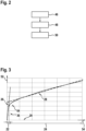
- Figure 3 shows a signal strength diagram.
- the signal strength diagram comprises an ordinate 52.
- the signal strength diagram comprises an abscissa 54.
- the output signal of the transimpedance amplifier 18 against a ground is plotted as an electrical voltage.
- On the abscissa 54 the light intensity of the flame 12 is plotted.
- the signal strength diagram comprises a first value range 22 on the abscissa 54.
- the first value range 22 comprises the first amplification factor 26.
- the signal strength diagram comprises the second value range 24 on the abscissa 54.
- the second value range 24 comprises the second amplification factor 28.
- the signal strength diagram shows a knee threshold 64.
- the knee threshold 64 shows the threshold from the first value range 22 to the second value range 24.
- This knee threshold 64 as the threshold between the first amplification factor 26 and the second amplification factor 28 is temperature dependent. However, this temperature dependence is eliminated by the temperature compensation with the temperature-dependent resistor.
- the temperature-dependent resistor is configured to compensate the temperature dependence of the electronic switch, which is about -2mV/°C.
Landscapes
- Engineering & Computer Science (AREA)
- Chemical & Material Sciences (AREA)
- Combustion & Propulsion (AREA)
- Mechanical Engineering (AREA)
- General Engineering & Computer Science (AREA)
- Photometry And Measurement Of Optical Pulse Characteristics (AREA)
Applications Claiming Priority (1)
| Application Number | Priority Date | Filing Date | Title |
|---|---|---|---|
| GB2319233.9A GB2636447A (en) | 2023-12-15 | 2023-12-15 | Monitoring device, burning appliance and signal amplification method |
Publications (1)
| Publication Number | Publication Date |
|---|---|
| EP4571190A1 true EP4571190A1 (de) | 2025-06-18 |
Family
ID=89662930
Family Applications (1)
| Application Number | Title | Priority Date | Filing Date |
|---|---|---|---|
| EP24217321.9A Pending EP4571190A1 (de) | 2023-12-15 | 2024-12-04 | Überwachungsvorrichtung, verbrennungsgerät und signalverstärkungsverfahren |
Country Status (2)
| Country | Link |
|---|---|
| EP (1) | EP4571190A1 (de) |
| GB (1) | GB2636447A (de) |
Citations (2)
| Publication number | Priority date | Publication date | Assignee | Title |
|---|---|---|---|---|
| US5589682A (en) * | 1995-06-07 | 1996-12-31 | General Electric Company | Photocurrent detector circuit with high sensitivity, fast response time, and large dynamic range |
| CN116545390A (zh) * | 2023-04-25 | 2023-08-04 | 武汉光迅科技股份有限公司 | 一种运算放大电路及光电检测系统 |
-
2023
- 2023-12-15 GB GB2319233.9A patent/GB2636447A/en active Pending
-
2024
- 2024-12-04 EP EP24217321.9A patent/EP4571190A1/de active Pending
Patent Citations (2)
| Publication number | Priority date | Publication date | Assignee | Title |
|---|---|---|---|---|
| US5589682A (en) * | 1995-06-07 | 1996-12-31 | General Electric Company | Photocurrent detector circuit with high sensitivity, fast response time, and large dynamic range |
| CN116545390A (zh) * | 2023-04-25 | 2023-08-04 | 武汉光迅科技股份有限公司 | 一种运算放大电路及光电检测系统 |
Also Published As
| Publication number | Publication date |
|---|---|
| GB2636447A (en) | 2025-06-18 |
| GB202319233D0 (en) | 2024-01-31 |
Similar Documents
| Publication | Publication Date | Title |
|---|---|---|
| US9872350B2 (en) | Power supply unit and related lighting system | |
| US4852544A (en) | Self-cleaning oven temperature control with multiple redundant oven temperature sensing elements | |
| US5694208A (en) | Sensor for detecting fine particles such as smoke or dust contained in the air | |
| GB2500993A (en) | Temperature corrected optical gas sensor | |
| GB2228790A (en) | Cooking stove | |
| JP7266436B2 (ja) | 電子装置を備えた光ガスセンサー及びそのような電子装置を用いて光電流と温度を組み合せて測定する方法 | |
| EP0071067B1 (de) | Verbrennungskontrolleeinrichtung | |
| EP4571190A1 (de) | Überwachungsvorrichtung, verbrennungsgerät und signalverstärkungsverfahren | |
| EP3339736B1 (de) | Flammendetektion für verbrennungsvorrichtungen | |
| US20030227694A1 (en) | Laser diode module, laser diode device and optical transmitter incorporating the same | |
| US6404342B1 (en) | Flame detector using filtering of ultraviolet radiation flicker | |
| KR100358576B1 (ko) | 가스검출기 | |
| US20040079888A1 (en) | Infrared detection device | |
| US4389124A (en) | Device for monitoring selected operating conditions of combustion within a solid fossil fuel burning furnace | |
| JPH06142063A (ja) | 放射体温計 | |
| US4135402A (en) | Thermocouple temperature detecting assembly | |
| US5955734A (en) | High temperature two-wire photocurrent detector circuit | |
| EP4571189A1 (de) | Überwachungsvorrichtung, verbrennungsgerät und selbsttestverfahren | |
| JP2511730B2 (ja) | 火炎検出器 | |
| EP0077648B1 (de) | Schaltung zur Regelung der Ausgangsspannung eines Elementes, so wie einer Photozelle | |
| KR100964145B1 (ko) | 광의 입출력이 일체화된 광감쇄형 센서, 광안정화방법 및 신호처리방법 | |
| US4546320A (en) | Total temperature probe buffer amplifier | |
| CN117769072A (zh) | 一种微波炉调控保护电路及微波炉 | |
| CN121433429A (zh) | 一种激光传感器的驱动电路及激光测速装置 | |
| EP3875929A1 (de) | Verfahren und elektronische verarbeitungseinheit zur messung und verarbeitung von optischen signalen zur temperaturmessung |
Legal Events
| Date | Code | Title | Description |
|---|---|---|---|
| PUAI | Public reference made under article 153(3) epc to a published international application that has entered the european phase |
Free format text: ORIGINAL CODE: 0009012 |
|
| STAA | Information on the status of an ep patent application or granted ep patent |
Free format text: STATUS: THE APPLICATION HAS BEEN PUBLISHED |
|
| AK | Designated contracting states |
Kind code of ref document: A1 Designated state(s): AL AT BE BG CH CY CZ DE DK EE ES FI FR GB GR HR HU IE IS IT LI LT LU LV MC ME MK MT NL NO PL PT RO RS SE SI SK SM TR |
|
| STAA | Information on the status of an ep patent application or granted ep patent |
Free format text: STATUS: REQUEST FOR EXAMINATION WAS MADE |
|
| 17P | Request for examination filed |
Effective date: 20251218 |
|
| STAA | Information on the status of an ep patent application or granted ep patent |
Free format text: STATUS: EXAMINATION IS IN PROGRESS |
|
| 17Q | First examination report despatched |
Effective date: 20260209 |