EP4571200A1 - Verfahren zur erneuerung einer gebäudeheizung eines gebäudes und erneuerung einer gebäudeheizung - Google Patents
Verfahren zur erneuerung einer gebäudeheizung eines gebäudes und erneuerung einer gebäudeheizung Download PDFInfo
- Publication number
- EP4571200A1 EP4571200A1 EP23216429.3A EP23216429A EP4571200A1 EP 4571200 A1 EP4571200 A1 EP 4571200A1 EP 23216429 A EP23216429 A EP 23216429A EP 4571200 A1 EP4571200 A1 EP 4571200A1
- Authority
- EP
- European Patent Office
- Prior art keywords
- heat pump
- fluid
- existing
- building
- water
- Prior art date
- Legal status (The legal status is an assumption and is not a legal conclusion. Google has not performed a legal analysis and makes no representation as to the accuracy of the status listed.)
- Pending
Links
Images


Classifications
-
- F—MECHANICAL ENGINEERING; LIGHTING; HEATING; WEAPONS; BLASTING
- F24—HEATING; RANGES; VENTILATING
- F24D—DOMESTIC- OR SPACE-HEATING SYSTEMS, e.g. CENTRAL HEATING SYSTEMS; DOMESTIC HOT-WATER SUPPLY SYSTEMS; ELEMENTS OR COMPONENTS THEREFOR
- F24D3/00—Hot-water central heating systems
- F24D3/08—Hot-water central heating systems in combination with systems for domestic hot-water supply
-
- F—MECHANICAL ENGINEERING; LIGHTING; HEATING; WEAPONS; BLASTING
- F24—HEATING; RANGES; VENTILATING
- F24D—DOMESTIC- OR SPACE-HEATING SYSTEMS, e.g. CENTRAL HEATING SYSTEMS; DOMESTIC HOT-WATER SUPPLY SYSTEMS; ELEMENTS OR COMPONENTS THEREFOR
- F24D3/00—Hot-water central heating systems
- F24D3/02—Hot-water central heating systems with forced circulation, e.g. by pumps
-
- F—MECHANICAL ENGINEERING; LIGHTING; HEATING; WEAPONS; BLASTING
- F24—HEATING; RANGES; VENTILATING
- F24D—DOMESTIC- OR SPACE-HEATING SYSTEMS, e.g. CENTRAL HEATING SYSTEMS; DOMESTIC HOT-WATER SUPPLY SYSTEMS; ELEMENTS OR COMPONENTS THEREFOR
- F24D11/00—Central heating systems using heat accumulated in storage masses
- F24D11/02—Central heating systems using heat accumulated in storage masses using heat pumps
- F24D11/0214—Central heating systems using heat accumulated in storage masses using heat pumps water heating system
-
- F—MECHANICAL ENGINEERING; LIGHTING; HEATING; WEAPONS; BLASTING
- F24—HEATING; RANGES; VENTILATING
- F24D—DOMESTIC- OR SPACE-HEATING SYSTEMS, e.g. CENTRAL HEATING SYSTEMS; DOMESTIC HOT-WATER SUPPLY SYSTEMS; ELEMENTS OR COMPONENTS THEREFOR
- F24D13/00—Electric heating systems
- F24D13/04—Electric heating systems using electric heating of heat-transfer fluid in separate units of the system
-
- F—MECHANICAL ENGINEERING; LIGHTING; HEATING; WEAPONS; BLASTING
- F24—HEATING; RANGES; VENTILATING
- F24D—DOMESTIC- OR SPACE-HEATING SYSTEMS, e.g. CENTRAL HEATING SYSTEMS; DOMESTIC HOT-WATER SUPPLY SYSTEMS; ELEMENTS OR COMPONENTS THEREFOR
- F24D17/00—Domestic hot-water supply systems
- F24D17/02—Domestic hot-water supply systems using heat pumps
-
- F—MECHANICAL ENGINEERING; LIGHTING; HEATING; WEAPONS; BLASTING
- F24—HEATING; RANGES; VENTILATING
- F24D—DOMESTIC- OR SPACE-HEATING SYSTEMS, e.g. CENTRAL HEATING SYSTEMS; DOMESTIC HOT-WATER SUPPLY SYSTEMS; ELEMENTS OR COMPONENTS THEREFOR
- F24D19/00—Details
- F24D19/10—Arrangement or mounting of control or safety devices
- F24D19/1006—Arrangement or mounting of control or safety devices for water heating systems
- F24D19/1009—Arrangement or mounting of control or safety devices for water heating systems for central heating
- F24D19/1039—Arrangement or mounting of control or safety devices for water heating systems for central heating the system uses a heat pump
-
- F—MECHANICAL ENGINEERING; LIGHTING; HEATING; WEAPONS; BLASTING
- F24—HEATING; RANGES; VENTILATING
- F24D—DOMESTIC- OR SPACE-HEATING SYSTEMS, e.g. CENTRAL HEATING SYSTEMS; DOMESTIC HOT-WATER SUPPLY SYSTEMS; ELEMENTS OR COMPONENTS THEREFOR
- F24D19/00—Details
- F24D19/10—Arrangement or mounting of control or safety devices
- F24D19/1006—Arrangement or mounting of control or safety devices for water heating systems
- F24D19/1066—Arrangement or mounting of control or safety devices for water heating systems for the combination of central heating and domestic hot water
- F24D19/1072—Arrangement or mounting of control or safety devices for water heating systems for the combination of central heating and domestic hot water the system uses a heat pump
-
- F—MECHANICAL ENGINEERING; LIGHTING; HEATING; WEAPONS; BLASTING
- F24—HEATING; RANGES; VENTILATING
- F24D—DOMESTIC- OR SPACE-HEATING SYSTEMS, e.g. CENTRAL HEATING SYSTEMS; DOMESTIC HOT-WATER SUPPLY SYSTEMS; ELEMENTS OR COMPONENTS THEREFOR
- F24D3/00—Hot-water central heating systems
- F24D3/10—Feed-line arrangements, e.g. providing for heat-accumulator tanks, expansion tanks ; Hydraulic components of a central heating system
-
- F—MECHANICAL ENGINEERING; LIGHTING; HEATING; WEAPONS; BLASTING
- F24—HEATING; RANGES; VENTILATING
- F24D—DOMESTIC- OR SPACE-HEATING SYSTEMS, e.g. CENTRAL HEATING SYSTEMS; DOMESTIC HOT-WATER SUPPLY SYSTEMS; ELEMENTS OR COMPONENTS THEREFOR
- F24D3/00—Hot-water central heating systems
- F24D3/18—Hot-water central heating systems using heat pumps
-
- F—MECHANICAL ENGINEERING; LIGHTING; HEATING; WEAPONS; BLASTING
- F24—HEATING; RANGES; VENTILATING
- F24H—FLUID HEATERS, e.g. WATER OR AIR HEATERS, HAVING HEAT-GENERATING MEANS, e.g. HEAT PUMPS, IN GENERAL
- F24H1/00—Water heaters, e.g. boilers, continuous-flow heaters or water-storage heaters
- F24H1/10—Continuous-flow heaters, i.e. heaters in which heat is generated only while the water is flowing, e.g. with direct contact of the water with the heating medium
- F24H1/101—Continuous-flow heaters, i.e. heaters in which heat is generated only while the water is flowing, e.g. with direct contact of the water with the heating medium using electric energy supply
-
- F—MECHANICAL ENGINEERING; LIGHTING; HEATING; WEAPONS; BLASTING
- F24—HEATING; RANGES; VENTILATING
- F24H—FLUID HEATERS, e.g. WATER OR AIR HEATERS, HAVING HEAT-GENERATING MEANS, e.g. HEAT PUMPS, IN GENERAL
- F24H15/00—Control of fluid heaters
- F24H15/20—Control of fluid heaters characterised by control inputs
- F24H15/212—Temperature of the water
- F24H15/215—Temperature of the water before heating
-
- F—MECHANICAL ENGINEERING; LIGHTING; HEATING; WEAPONS; BLASTING
- F24—HEATING; RANGES; VENTILATING
- F24H—FLUID HEATERS, e.g. WATER OR AIR HEATERS, HAVING HEAT-GENERATING MEANS, e.g. HEAT PUMPS, IN GENERAL
- F24H15/00—Control of fluid heaters
- F24H15/20—Control of fluid heaters characterised by control inputs
- F24H15/242—Pressure
-
- F—MECHANICAL ENGINEERING; LIGHTING; HEATING; WEAPONS; BLASTING
- F24—HEATING; RANGES; VENTILATING
- F24H—FLUID HEATERS, e.g. WATER OR AIR HEATERS, HAVING HEAT-GENERATING MEANS, e.g. HEAT PUMPS, IN GENERAL
- F24H4/00—Fluid heaters characterised by the use of heat pumps
- F24H4/02—Water heaters
-
- F—MECHANICAL ENGINEERING; LIGHTING; HEATING; WEAPONS; BLASTING
- F24—HEATING; RANGES; VENTILATING
- F24H—FLUID HEATERS, e.g. WATER OR AIR HEATERS, HAVING HEAT-GENERATING MEANS, e.g. HEAT PUMPS, IN GENERAL
- F24H9/00—Details
- F24H9/0005—Details for water heaters
-
- F—MECHANICAL ENGINEERING; LIGHTING; HEATING; WEAPONS; BLASTING
- F24—HEATING; RANGES; VENTILATING
- F24H—FLUID HEATERS, e.g. WATER OR AIR HEATERS, HAVING HEAT-GENERATING MEANS, e.g. HEAT PUMPS, IN GENERAL
- F24H9/00—Details
- F24H9/12—Arrangements for connecting heaters to circulation pipes
- F24H9/13—Arrangements for connecting heaters to circulation pipes for water heaters
-
- F—MECHANICAL ENGINEERING; LIGHTING; HEATING; WEAPONS; BLASTING
- F24—HEATING; RANGES; VENTILATING
- F24D—DOMESTIC- OR SPACE-HEATING SYSTEMS, e.g. CENTRAL HEATING SYSTEMS; DOMESTIC HOT-WATER SUPPLY SYSTEMS; ELEMENTS OR COMPONENTS THEREFOR
- F24D2200/00—Heat sources or energy sources
- F24D2200/12—Heat pump
-
- F—MECHANICAL ENGINEERING; LIGHTING; HEATING; WEAPONS; BLASTING
- F24—HEATING; RANGES; VENTILATING
- F24H—FLUID HEATERS, e.g. WATER OR AIR HEATERS, HAVING HEAT-GENERATING MEANS, e.g. HEAT PUMPS, IN GENERAL
- F24H15/00—Control of fluid heaters
- F24H15/40—Control of fluid heaters characterised by the type of controllers
- F24H15/493—Control of fluid heaters characterised by the type of controllers specially adapted for enabling recognition of parts newly installed in the fluid heating system, e.g. for retrofitting or for repairing by replacing parts
-
- F—MECHANICAL ENGINEERING; LIGHTING; HEATING; WEAPONS; BLASTING
- F24—HEATING; RANGES; VENTILATING
- F24H—FLUID HEATERS, e.g. WATER OR AIR HEATERS, HAVING HEAT-GENERATING MEANS, e.g. HEAT PUMPS, IN GENERAL
- F24H2250/00—Electrical heat generating means
- F24H2250/08—Induction
Definitions
- the invention relates to a method for renewing a building heating system of a building, in particular for heating water, such as tap water and/or utility water, of a building water system.
- the invention also relates to renewed building heating system obtained by applying the method according to the invention.
- the invention further relates to a kit of parts for renewing a building heating system by applying the method according to the invention.
- Conventional residential heating systems typically comprise a single centralized heat source, like a gas boiler, from which heat is supplied to a number of recipients within the building. These systems are relatively low in efficiency due to significant losses introduced by transporting heat over a large distance through the building whenever a recipient initiates a heat request.
- At least one of these objectives can be achieved by providing a method according to the preamble, comprising the steps of:
- the method and the renewed building heating system obtained via said method according to the invention have a plurality of advantages.
- the heating system no longer requires the use of oil or gas boilers, which reduces the emission of the heating system according to the invention to zero.
- a (new) heat pump preferably to the existing - air inlet pipe and/or the existing air inlet opening, as well as to the existing flue gas discharge pipe and/or the existing flue gas outlet opening, use is made of the existing air conducting infrastructure, which allows an efficient, easy, and swift installation of the heat pump to replace the existing fuel source.
- the heat pump is connected to one or more new air ducts which is/are directly connected to the existing air inlet opening and/or existing flue gas outlet opening
- the heat pump is preferably connected to the existing air inlet pipe and the existing flue gas discharge pipe, wherein optionally at least one pipe adapter is positioned in between the heat pump and the existing pipes.
- the existing flue gas discharge pipe or the existing air inlet pipe or the assembly of said existing flue gas discharge pipe and said existing air inlet pipe is connected to an air intake duct of the heat pump to conduct into the heat pump.
- an air outlet (duct) of the heat pump may be free from any connection to existing pipes and/or existing openings and may discharge cooled air directly into a building space (a room) where the heat pump is located.
- the air inlet opening is typically applied in an outer wall of a building housing the building heating system to allow the intake of fresh air from the outside.
- the existing flue gas opening is preferably (also) applied in an outer wall of said building to allow discharge of flue gas directly into the outside atmosphere.
- the existing fluid line to which the heat pump is connected may conduct water. It is imaginable that the fluid line remains to conduct water after connecting the heat pump to said fluid line. It is also imaginable that another a single-component working fluid (e.g. glycol or ammonia), or a multi-component working fluid, such as a mixture of water and ammonia, will be conducted through the (working) fluid line, in particular to realize a more efficient heat transfer within the renewed building heating system. More details on this will be described below.
- a single-component working fluid e.g. glycol or ammonia
- a multi-component working fluid such as a mixture of water and ammonia
- the fluid line to which the heat pump is connected may be or may become part of an intermediate working fluid line (also referred to as step j) of the method according to the invention), such as a working fluid circuit, for conducting a working fluid (e.g. water, glycol, ammonia, as indicated above), acts as an intermediary heat transfer fluid to transfer heat from a source fluid, such as (outside) air, to water conducted through at least one water line of the building water system.
- a source fluid such as (outside) air
- water lines are a tap water line and a central heating line. It is imaginable the that working fluid line, which preferably forms a working fluid circuit, in particular a closed working fluid circuit, forms part of the central heating line of the building water system.
- the working fluid circuit may be water, which water is heated by the heat pump and/or heating tubes and/or (alternative) auxiliary heat sources.
- This heated water of the working fluid line may optionally be directly used to heat the building (at least partially) as well to transfer heat to tap water of a tap water line.
- a heat pump is used, the (working) fluid can be heated in a relatively energy-efficient manner.
- an air source heat pump is used, which is configured to extract heat energy from air, preferably outside air, to subsequently transfer at least a substantial part of the extracted heat to the (working) fluid.
- the disconnected fuel source will no longer be used, and may be closed off (sealed) and optionally be removed.
- the building heating system according to the invention can be used for example as residential heating system, in particular home/domestic heating system, or as commercial heating system.
- the method comprises step d): connecting said heat pump to a control unit for controlling said heat pump.
- the control unit is preferably a programmable and/or pre-programmed logic controller (PLC) and/or an energy management system (EMS).
- PLC programmable and/or pre-programmed logic controller
- EMS energy management system
- the method comprises step e): connecting said control unit to at least one (existing and/or new) fluid temperature sensor, such as a water temperature sensor, and/or at least one (existing and/or new) fluid pressure sensor, such as a water pressure sensor, of the building heating system.
- the method comprises step f): connecting at least one new fluid temperature sensor, such as a water temperature sensor, and/or at least one new fluid pressure sensor, such as a water pressure sensor, to at least one fluid line, in particular a water line, in particular a tap water line and/or a central heating line, of the building heating system.
- a new fluid temperature sensor such as a water temperature sensor
- a new fluid pressure sensor such as a water pressure sensor
- the control unit to control the heat pump and/or any other heat source to heat the fluid in the fluid line, based upon one or more temperature values measured by the one of more fluid temperature sensors and/or one or more pressure values measured by the one or more fluid pressure sensors.
- This demand-based control of the heat source(s) is typically preferred from an efficiency and energy point of view.
- the method may comprise, and preferably comprises, step g): connecting at least one heating tube and/or at least one alternative auxiliary heat source, directly or indirectly, to the heat pump to provide additional heat energy to the fluid to be heated. This allows the fluid to be heated more quickly to a higher temperature (when needed and if needed).
- the method comprises step h): connecting the control unit to the at least one heating tube and/or the at least one alternative auxiliary heat source, for controlling the at least one heating tube and/or the at least one alternative auxiliary heat source, preferably wherein the control unit is configured to switch on and off the heating tube, dependent on one or more temperature values measured by one or more temperature sensors and/or one or more fluid pressure sensors.
- Step h) allows the heating system to be configured, by means of its control unit, to modularly control, in particular switch on or off, heat sources, like the heating tubes and optionally the heat pump.
- the temperature (and/or pressure) can be measured at various locations within the heating system, which serves as input for the (pre-programmed) control unit to, preferably individually, control the heating components of the heating system, including the heating tubes and optionally the heat pump.
- control unit may be configured to simultaneously or successively to switch on at least one further heating tube (or alternative auxiliary heat source) in case the measured water flow exceeds a, preferably predefined, period of time and/or in case the measured temperature increase over a predefined period of time remains below a temperature threshold value. Additionally or alternatively, the control unit may be configured to act as PID controller and/or may comprise at least one PID controller to control one or more heating tubes and optionally the heat pump.
- a PID controller (a proportional-integral-derivative controller) continuously calculates an error value as the difference between a desired setpoint (SP) (which may be considered as threshold value) and a measured process variable (PV) and applies a correction based on proportional, integral, and derivative terms (denoted P, I, and D respectively).
- SP desired setpoint
- PV measured process variable
- This PID output signal which is typically an analog signal, may be converted into a discrete signal (ON or OFF signal) and/or may be used to generate a discrete signal (ON or OFF signal).
- one or at least two heating tubes is/are positioned at a downstream side of the heat pump and an upstream side of the at least one heat exchanger.
- the heat pump typically acts as a primary heat source
- the heat tubes act as secondary heat sources to further heat the fluid, such as water or an intermediate working fluid (if necessary)
- positioning of components is preferred as this allows measuring the temperature of the fluid, such as water or an intermediate working fluid directly downstream of the heat pump to decide whether the heating tubes should be switched on as well, and if so, which heating tubes should be switch on as well, to bring the temperature of the fluid, such as water or an intermediate working fluid, to a desired level.
- At least two heating tubes are or could be positioned at an upstream side of the heat pump and at a downstream side of the at least one heat exchanger. It is imaginable that the heating tubes act as primary heat sources, and the heat pump acts as a secondary heat source to further heat the (working) fluid (if necessary). This makes it possible, for example, in case the measured temperature of the fluid, such as water or an intermediate working fluid, is below a threshold value to switch on the heat pump to further heat the working fluid and/or water to a desired temperature level. Additionally, it makes it possible, for example, in case the measured temperature of the working fluid and/or water is above a threshold value to switch off the heat pump to reduce (unnecessary) energy consumption.
- the fluid such as water or an intermediate working fluid
- a combination is also imaginable wherein one or more heating tubes is/are positioned, preferably directly, downstream of the heat pump and wherein one or more other heating tubes is/are positioned, preferably directly, upstream of the heat pump. It is imaginable to position one or more heating tubes relatively close to and at an upstream side of the heat exchanger to reduce loss of heat during transportation of the heated (working) fluid through the (working) fluid line, which is advantageous from an energetic point of view. To this end, relatively close may for example be less than 10 meter, preferably less than 7 meter, more preferably less than 5 meter, even more preferably less than 4, 3, 2, or 1 meter as measured along the (working) fluid line.
- the electrical heating tubes used in the heating system according to the invention are designed for flow-through of the fluid, such as water or an intermediate working fluid. During flow-through of the (working) fluid, the (working) fluid can be heated by the heating tubes (when activated by the control unit).
- At least two heating tubes are connected in parallel orientation in the fluid line, such as an intermediate working fluid line and/or a water line.
- a diameter of at least one heating tube, preferably each heating tube is smaller than a diameter of an, preferably each, adjacent (main) conduit of the (working) fluid line.
- the sum of diameters of the parallel heating tubes is larger than a diameter of an, preferably each, adjacent conduit of the (working) fluid line. This allows the (working) fluid flow rate to drop within the heating tubes, which lengthens the residence time of the (working) fluid within the heating tubes, which intensifies the heat transfer from the heat tube(s) to the (working) fluid.
- heating tubes are connected in series in the (working) fluid line.
- various heating tubes are integrated into a single heating tube having a plurality of, preferably individually controllable, heating sections.
- Each heating section may, for example, by formed and/or comprise a heating coil, which coils are oriented in series (one coil being positioned downstream of the other coil as seen in the (working) fluid flow direction).
- Each heating coil is thereby preferably wound around the same tube (body).
- At least one electrical heating tube is an induction heating tube.
- the induction heating tube is configured to heat the (working) fluid by means of induction heating.
- Induction heating uses the principle of the action of the electromagnetic field described by Maxwell's equations on ferromagnetic material.
- the electrically conductive object here an electrically conductive tube, is inserted into the alternating electromagnetic field of the induction coil during the induction heating through which the alternating current passes.
- swirled currents are induced in the heated tube, which have the opposite orientation as the current in the induction coil. Heating occurs due to resistive and hysteresis losses, the proportion of electrical and magnetic components depending on the electrical and magnetic properties of the heated material.
- the heat is generated directly inside the material of the tube, which is subsequently be transferred at least partially to the (working) fluid.
- the tube and the inductor (surround coil) are not in direct mechanical contact with each other to prevent short-circuiting.
- At least one coil of said induction heating tube is connected to an alternating current source.
- said at least one coil is wound, preferably at a coupling distance, around an electricity conductive tube, such as a metal tube, in particular a copper and/or a steel tube, of said heating tube.
- said induction heating tube is connected or a connectable to an alternating current source, such as the mains (with a default frequency of 50 Hz), wherein at least one frequency converter is positioned in between the alternating current source and said induction heating tube, wherein said frequency converter is configured to increase a default frequency value of the alternating current source to a higher frequency value.
- the frequency converter if applied, is preferably configured to produce a frequency which is x times the default frequency of the alternating current source, wherein x is preferably at least 100, more preferably at least 1,000.
- At least one electrical heating tube may be an electrical resistance heating tube or an Ohmic heating tube comprising at least one electrical resistance heating element, such as a heating coil, configured to generate heat to be transferred to the (working) fluid conducted through said heating tube.
- Said heating element is preferably connected or connectable to an electrical power source.
- the heating element may e.g. be a heating coil or heating strip, which may be positioned either around and/or inside at least one heating tube for flow-through of the (working) fluid.
- Each heating tube is preferably configured to generate at least 1kW, preferably between 1 and 5 kW, more preferably between 2 and 4 kW, of heating power.
- the total assembly of heating tubes is configured to generate at least 2 kW, preferably between 2 and 10 kW, more preferably between 4 and 7 kW, of heating power.
- Each heating tube and/or the total assembly of heating tubes (or alternative auxiliary heating sources) may be configured to generate at least 10 kW of heating power.
- the heat pump is preferably configured to generate between 1 and 5 kW, preferably between 1 and 3.5 kW, of heating power.
- the ratio of the power input and the power output of the heat pump is between 6:11 and 1:5.
- the ratio of the power input and the power output of the heating system (heat pump, and heating tubes, and control unit) is between 60:61 and 2:3.
- the fluid line such as the working fluid line and/or the water line, comprises at least one alternative auxiliary heat source to at least partially further heat the (working) fluid.
- the (working) fluid line may comprise the heat source instead of or in addition to at least one of the at least two heating tubes. It is conceivable that instead of the at least two heating tubes, the (working) fluid line comprises at least one heat source.
- the heat source is configured to heat the working fluid electrically and/or by means of green energy or renewable energy.
- at least one alternative auxiliary heat source i may for example be a solar heater, a geothermal heater, an additional heat pump, and the like.
- the control unit is preferably configured to individually switch on and off the electrical heating tubes and/or one or more parts of a heating tube, dependent on one or more temperature values measured by one or more temperature sensors, preferably including temperature values relating to the temperature of the (working) fluid and the water heated and/or to be heated.
- the control unit acts as central and sole control unit.
- the control unit is configured to communicate with each temperature sensor of the heating system. This communication between the control unit that at least one, preferably each, temperature sensor and/or the heating tubes and/or the heat pump may be either wired and/or wirelessly.
- the control unit is preferably (also) configured to communicate building heating system related data to at least one external device, such as a display, an external computer, a smartphone, and/or a tablet to allow persons to monitor the status of the heating system and optionally to modify the programming of the control unit and hence the control of the building heating system.
- a further advantage of the method and/or the building heating system according to the invention is that the heating system is or may be configured, by means of its control unit, to modularly control, in particular switch on or off, heat sources, like the heating tubes and optionally the heat pump.
- the temperature can be measured at various locations within the heating system, which serves as input for the (pre-programmed) control unit to, preferably individually, control the heating components of the heating system, including the heating tubes and optionally the heat pump.
- This makes it possible, for example, in case the measured temperature of the working fluid and/or water is below a threshold value to switch on one or more heating tubes to further heat the working fluid and/or water to a desired temperature level. Additionally, it makes it possible, for example, in case the measured temperature of the working fluid and/or water is above a threshold value to switch off one or more heating tubes to reduce (unnecessary) energy consumption.
- the heat pump is preferably an air source heat pump.
- This air source heat pump typically comprises at least one compressor, at least one condenser, and at least one expansion device, in particular at least one expansion valve, and at least one evaporator, connected by fluid conduits carrying a heat pump fluid, wherein the evaporator is provided with an air intake duct and an air outlet duct, wherein the heat pump further comprises an air fan which is preferably provided in or connected to the air intake duct.
- the heat pump fluid may, for example, comprise one or more chlorofluorocarbons, one or more hydrochlorofluorocarbons, one or more fluorocarbons, propane, butane, isobutane, ammonia, sulphur dioxide, or mixtures thereof.
- the heat pump fluid may be a liquid, a gas, or combination thereof.
- the condenser is preferably provided with at least one working fluid duct making part of the working fluid line, wherein said working fluid duct is preferably connected to the heating tubes.
- the heat pump comprises a housing, wherein at least two heating tubes are connected to said housing and/or are accommodated within said housing. This allows the combination of the heat pump and at least two heating tubes to be produced, sold and installed as a heating system unit. This may seriously facilitate installation of the heating system.
- the housing may be a substantially closed housing, or an open housing, and may even be formed at least partially by a shared support structure for supporting the heat pump and the heating tubes.
- the heat pump is typically connected or connectable to an electrical power source. It is imaginable that the system comprises at least one solar power generator for powering the heat pump and the heating tubes at least partially.
- the method comprises step k): connecting at least one working fluid pump to the working fluid line to pump the working fluid through the working fluid line.
- the working fluid line preferably comprises at least one storage container for (temporarily) storing heated (working) fluid, wherein said storage container is preferably configured for flow-through of (working) fluid during circulation of working fluid in the working fluid line.
- Connecting said at least one (working) fluid storage container, preferably existing (working) fluid storage container to the (working) fluid line to store heated (working) fluid is also referred to as step I) of the method according to the invention.
- the storage container may be a buffer tank and/or a storage vessel.
- the storage container has a (working) fluid storage volume of at least 45 litre.
- the storage container may, for example, have a (working) fluid storage volume of between 100 and 150 litre, such as 120 litre.
- the maximum temperature of the (working) fluid within the storage container is typically 95 degrees Celsius.
- a part of at least one water line, such as a tap water line is guided through said storage container for preheating water by said (working) fluid within said storage container. This may, for example, preheat relatively cold water having a minimum temperature of 10 degrees Celsius to a temperature of between 10 and 75 degrees Celsius.
- the conduct part of the water line enclosed by the storage container is preferably coil-shaped to increase the length of the conduct part, and hence the heat transfer capacity from the (working) fluid to the water.
- the heating system preferably comprises at least one water pump for pumping water through at least one water line of the building water system.
- each water line is provided with its own water pump.
- the system comprises a plurality of separated water lines of the building water system, wherein each of at least two water lines are connected to a water heat exchanger for heating water by the working fluid (intermediate fluid).
- the working fluid to water heat exchanger is preferably a plate heat exchanger, more preferably a counter-flow plate heat exchanger wherein the working fluid and the water to be heated are conducted in counter-flow through the plate heat exchanger.
- the building water system comprises at least one tap water line and at least one central heating water line, wherein each of said lines are connected to a water heat exchanger for heating water by the working fluid.
- the tap water related heat exchanger is positioned directly downstream of the heat tubes to allow practically instantaneously delivery of hot tap water when needed.
- the central heating system related heat exchanger may be positioned downstream of the tap water related heat exchanger as this central heating system normally does not require sudden peak demands of hot water.
- the system comprises at least one safety circuit configured to detect overheating and/or boiling dry of the (working) fluid line and for switching off the heat pump and the heating tubes (and/or other auxiliary heat source(s) (if applied)) in case overheating and/or boiling dry of the working fluid line is detected, wherein said safety circuit is preferably unconnected to the control unit.
- the method preferably comprises step m): connecting at least one safety circuit to the working fluid line to detect overheating and/or boiling dry of the working fluid line and for switching of the heat pump in case overheating and/or boiling dry of the working fluid line is detected.
- At least one pipe adapter is placed in between the heat pump and the existing air inlet pipe and/or the existing flue gas discharge pipe.
- the pipe adapter may, for example, be a branched connecting tube, such as a Y-branched connecting tube or a T-branched connecting tube.
- the pipe adapter, in particular connecting tube comprises an inner tube portion and an outer tube portion which concentrically surrounds at least a part of the inner tube portion.
- the existing air inlet pipe concentrically encloses at least a part of the existing flue gas outlet pipe to take advantage of the relatively high enthalpy of the flue gas to preheat the fresh inlet air.
- this leads to a considerable reduction of the discharge temperature of the flue gas and an increase of the fresh air inlet temperature. This reduces the thermal difference, as a result of which a boiler can achieve the same heat result using less energy.
- the heat pump comprises an air inlet opening and an air outlet opening
- the existing air inlet pipe for air to be cooled
- the existing air outlet pipe for cooled air
- the heat pump may inversely be connected to the existing air pipe assembly. It is also imaginable that the assembly of said existing flue gas discharge pipe and said existing air inlet pipe is connected to the air intake duct of the heat pump to conduct air into the heat pump. This will generally increase the air intake capacity, and hence the effective capacity of the heat pump.
- the invention further relates to a method, in particular a computer-implemented method, for controlling the building heating system according to the invention, in particular obtained by applying the method according to the invention, wherein comprising the step of, operating the control unit to individually control and/or switch on and/or off, one or more electrical heating tubes and optionally the heat pump, at least partially based upon at least one temperature detected by said at least one temperature sensor.
- the control unit receives during this step a plurality of temperature values originating from different temperature sensors, and optionally one or more pressure values originating from one or more pressure sensors, to control the heat tubes and optionally the heat pump. Examples of such control have been give above and are described below in more detail.
- the control unit may switch one or more heat tubes off.
- the control unit may be programmed to switch off the heat tubes and optionally the heat pump.
- the control unit is programmed with computer-readable instructions configured to operate the building heating system. These instructions may include all data required to allow the control unit to autonomously control the building heating system.
- situation dependent parameters such as the heat capacity and/or diameters of the heat tubes and the capacity of the heat pump.
- data are normally stored on at least one storage medium and/or memory of the control unit. It is optionally imaginable that a part of said data, such as the situation dependent parameters, are not stored within the control unit, but are externally stored in a computer network and/or are stored in the Internet Cloud, wherein the control unit has access to said externally stored data.
- the invention moreover relates to a computer program product comprising a non-transitory computer-readable medium having stored thereon computer-readable instructions for the control unit for operating the building heating system according to the invention, in particular obtained by applying the method according to the invention.
- the computer-readable medium makes part of the control unit.
- These instructions typically comprise code for receiving sensor values originating from one or more sensor, including one or more temperature sensors, of the building heating system, and code to, preferably individually, control the heat tubes and optionally the heat pump, based upon the received sensor values and preferably based upon at least one decision-making algorithm.
- This computer program product optionally at least partially prestored on a control unit, may optionally be marketed separately from the heat pump and the heat tubes.
- Said computer-readable medium may be any type of memory device, including, for example, one or more of a removable non-volatile random-access memory, a hard disk drive, a floppy disk, a CD-ROM, a DVD-ROM, a USB memory, an SD memory card, or a similar computer-readable medium known in the art.
- the invention further relates to a renewed building heating system obtained by applying the method according to the invention.
- the control unit is configured to individually control and/or switch on and/or off, the heat pump, and one or more electrical heating tubes and/or one or more auxiliary heat sources, at least partially based upon at least one temperature detected by said at least one temperature sensor and/or said at least one pressure sensor.
- the invention moreover relates to a kit of parts for renewing a building heating system by applying the method according to the invention, comprising:
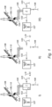
- FIG. 1 schematically shows a first embodiment of a method for renewing a building heating system of a building according to the invention.
- the building heating system to be renewed I) comprises an existing boiler 1, which may be a central heating oil boiler or a central heating gas boiler.
- the boiler 1 is, directly or indirectly, connected to an existing fuel source 108, for example an oil pipe or a gas pipe.
- the boiler 1 is, directly or indirectly, connected to an existing fluid line 103, such as a (tap) water line.
- the fluid line 103 is configured to conduct fluid to be heated, such as (tap) water, to the boiler 1 and to discharge heated fluid, such as heated water, from the boiler 1.
- the boiler 1 is preferably configured to heat the conducted fluid from a first temperature to a second higher temperature. Heated fluid may be extracted from the fluid line 103 at the downstream side of the boiler 1. At the downstream side of the boiler 1 the fluid line 103 may be, directly or indirectly, connected a tap and/or a shower 107 and/or a washing machine and/or a dish washer and/or a radiator, and the like, to be provided with heated fluid. Furthermore, the boiler 1 is, directly or indirectly, connected to an existing air inlet pipe 105 which is, directly or indirectly, connected to an existing air inlet opening 109 to allow air to be led through the boiler 1. The air inlet opening 109 may be provided in a wall of the building.
- the air inlet opening 109 is provided in a roof 106 of the building.
- the air inlet opening 109 may, however, be provided in any wall of the building.
- the boiler 1 is, directly or indirectly, connected to an existing flue gas discharge pipe 104 connected to an existing flue gas outlet opening 110 for discharging boiler generated flue gas, in particular for discharging boiler generated flue gas from the building.
- the flue gas outlet opening 110 may be provided in a wall of the building.
- the flue gas opening 110 is provided in a roof 106 of the building.
- the air inlet opening 109 and the flue gas opening 110 are provided in a same opening of the wall of the building, here in the roof 106 of the building.
- step a) the existing boiler 1 of the building heating system is disconnected from the existing fuel source 108, the existing fluid line 103, the existing air inlet pipe 105 and/or from the existing flue gas discharge pipe 104.
- step b) the boiler is removed or dismounted.
- step b) is performed prior to step a) or simultaneously with step a). It is imaginable that the existing fluid line 103 and/or the existing fuel source are closed off during step a) and/or during step b). The result of the completed steps a) and b) can be observed in the middle II) of the figure.
- an air source heat pump 2 is connected to the existing fluid line 103, the existing air inlet pipe 105 and/or the existing air inlet opening 109, and to the existing flue gas discharge pipe 104 and/or the existing flue gas outlet opening 110, as shown on the right side III) of the figure.
- the heat pump 2 is configured to heat the fluid of the fluid line 103. Heated fluid may subsequently be extracted from the fluid line 103 at the downstream side of the heat pump 2.
- the existing fuel source 108 is not needed by the air source heat pump 2.
- FIG. 2 schematically shows an embodiment of a renewed building heating system 200 obtained by applying the method according to the invention.
- the boiler was replaced by an air source heat pump 2, as shown in figure 1 .
- the shown air source heat pump 2 comprises an air intake duct Ai and an air outlet duct Ao.
- the air source heat pump 2 is connected to the existing air inlet pipe 105 and to the existing flue gas discharge pipe 104.
- the air intake duct Ai is connected to the existing flue gas discharge pipe 104 and the air outlet duct Ao is connected to the existing air inlet pipe 105.
- the heat pump 2 is configured to discharge relatively cold air via the existing air inlet pipe 105 and to extract relatively warm or hot air via the existing flue gas discharge pipe 104.
- This configuration is favourable, since the existing air inlet pipe 105 is designed to conduct relatively cold air and the existing flue gas discharge pipe 104 is designed to conduct relatively hot gas. It is, however, also imaginable that the air intake duct Ai is connected to the existing air inlet pipe 105 and the air outlet duct Ao is connected to the existing flue discharge pipe 104.
- the heat pump 2 further comprises a compressor 23, a condenser 24, an expansion valve 25, and an evaporator 22 which are connected by fluid conduits carrying a heat pump fluid H.
- the shown evaporator 22 is provided with the air intake duct Ai and the air outlet duct Ao.
- the shown air intake duct Ai is provided with an air fan 21 or a ventilator which is preferably provided in or connected to the air inlet duct Ai.
- the air fan 21 is configured to direct relatively hot air into the heat pump 2.
- the evaporator 22 is configured to at least partially heat the heat pump fluid H, for example by absorbing heat from the relatively hot air.
- the heat pump is connected to the fluid line.
- the shown condenser 24 is provided with a fluid duct configured to connect the heat pump 2 to the fluid line.
- the heat pump fluid H is at least partially in heat exchanging contact with the fluid of the fluid line, preferably at least partially in the condenser 24, to heat the fluid from a first temperature T1 to a second higher temperature T2.
- the heat pump 2 is connected to an intermediate working fluid line conducting a working fluid W, according to step j) of the invention. Consequently, the heat pump fluid H is at least partially in heat exchanging contact with the working fluid W, preferably at least partially in the condenser 24, to heat the working fluid W.
- An enlarged cross-sectional view of the rectangular portion 300 of the renewed building heating system 200 is shown in figure 3 .
- the shown renewed building heating system 200 further comprises auxiliary heat sources 5 which are, directly or indirectly, connected to the heat pump 2, preferably according to step g) of the method.
- the auxiliary heat sources 5 are configured to provide additional heat energy to the fluid W to be heated.
- the auxiliary heat sources 5 are three heating tubes 5.
- the heating tubes 5 are connected to the intermediate working fluid line.
- the three heating tubes 5 are connected to the intermediate working fluid line in a parallel orientation.
- the heating tubes 5, or the auxiliary heat sources 5, may be arranged at the downstream side of the heat pump 2, in particular according to step g) of the method.
- the heating tubes 5, may however, (also) be arranged at the upstream side of the heat pump 2.
- the shown heating tubes 5 are connected to the intermediate working fluid line at the downstream side of the heat pump 2.
- the heat pump 2 is, directly or indirectly, connected to a control unit 14 for controlling the heat pump 2.
- the heat pump 2 may be wirelessly or wired be connected to the control unit 14.
- the control unit 14 is also connected to at least one heating tube 5 for controlling the at least one heating tube 5, preferably according to step h) of the method.
- the shown control unit 14 is further connected to (existing and/or new) fluid temperature sensors 13, such as a water temperature sensor 131 or a working fluid temperature sensor 13, and/or at least one (existing and/or new) fluid pressure sensor 41, such as a water pressure sensor 141 or a working fluid pressure sensor 41, of the building heating system.
- control unit 14 to control the heat pump 2 and/or a heat source, such as the heating tubes 5, to heat the fluid in the fluid line, based upon one or more temperature values measured by the one of more fluid temperature sensors 13, 131 and/or one or more pressure values measured by the one or more fluid pressure sensors 41, 141.
- the (existing and/or new) temperature sensors 13, 131 are provided at various locations along the fluid line and/or (existing and/or new) pressure sensors 41, 141 are provided at various locations along the fluid line.
- a temperature sensor 13 may for example be provided downstream of the heating tubes 5 and upstream of a first heat exchanger 81. In the shown embodiment, a temperature sensor 13 is provided between the heat pump 2 and the heating tubes 5 to measure the temperature of the working fluid W before entering the heating tubes 5.
- the heating tubes 5 are preferably configured to cooperatively heat the working fluid W up to 95 degrees Celsius.
- a temperature difference ⁇ Tb may be defined by the difference in temperature of the working fluid W prior to entering the heating tubes 5 and the temperature of working fluid W after flow-through the heating tubes 5.
- the maximum temperature difference ⁇ Tb is 85 degrees Celsius.
- the working fluid W is preferably heated by the heating tubes 5 and the heat pump 2.
- the maximum temperature of the working fluid W passed through both the heating tubes 5 and the heat pump 2 is 95 degrees Celsius.
- a pressure sensor 41 is provided downstream of the heating tubes 5 and upstream of two heat exchangers 81, 82. It is imaginable, that when the pressure measured by the pressure sensor 41 is above a threshold value that a safety valve 37 opens to decrease the pressure in the intermediate working fluid line.
- the control unit 14 is configured to modularly control the heating tubes 5 and optionally the heat pump 2, preferably based upon the input of at least one temperature sensor 13, 131. For example, if the measured temperature of working fluid W measured by the temperature sensor 13 located upstream from the heating tubes 5 is below a threshold value the control unit 14 may be configured to switch on one or multiple heating tubes 5 to further heat the working fluid W to a desired temperature.
- the shown control unit 14 is connected or connectable to a an external device 44, such as a display to allow persons or users to communicate building heating system related data and/or to monitor the status of the heating system.
- a an external device 44 such as a display to allow persons or users to communicate building heating system related data and/or to monitor the status of the heating system.
- the shown renewed building heating system 200 comprises two exchangers 81, 82 which are serially connected to the intermediate working fluid line.
- the working fluid W conducted in the intermediate working fluid line may be configured to act as an intermediary heat transfer fluid to transfer heat to a first fluid F1 and/or a second fluid F2.
- a first heat exchanger 81 comprises a first inlet 91 and a first outlet 92 configured to be connected to the intermediate working fluid line.
- the first heat exchanger 81 further comprises a second inlet 93 and a second outlet 94 connected or connectable to a first fluid line comprising a first fluid F1.
- the first fluid line is a tap water line comprising tap water.
- the tap water line comprising tap water is heated in the first heat exchanger 81, provided upstream from the second heat exchanger 82, to allow the tap water to be heated relatively quickly.
- the first heat exchanger 81 may be configured to transfer heat from the working fluid W to the first fluid F1, such as water, of the first fluid line.
- the temperature of the first fluid F1 prior to entering the first heat exchanger 81 may be between 10 - 65 degrees Celsius.
- the first fluid F1 is heated by the first heat exchanger 81 up to 65 degrees Celsius.
- the first fluid line comprises a flow sensor or flow switch 46.
- the shown flow switch 46 is arranged upstream of the first heat exchanger 81.
- the flow switch 46 may be configured to monitor the flow rate and/or the pressure of the first fluid F1 in the first fluid line.
- the flow switch 46 is configured to activate the first heat exchanger 81 when the first fluid F1 exceeds a predetermined flow rate.
- a flow switch 46 is (also) provided in a second fluid line and/or in the intermediate working fluid line and/or in the fluid line.
- a water temperature sensor 131 is provided to measure the temperature of the first fluid F1.
- the shown temperature sensor 131 is provided downstream of the first heat exchanger 81.
- the temperature sensor 131 may be connected or connectable to the control unit 14, wherein the control unit 14 is configured to control the heat first exchanger 81 based upon the temperature detected by the temperature sensor 131. For example, if the measured temperature of the first fluid F1 measured by the temperature sensor 131 located upstream of the first heat exchanger 81 is below a threshold value the control unit may be configured to switch on one or multiple heating tubes 5 to (further) heat the first fluid F1 to a desired temperature.
- a second heat exchanger 82 may be provided at the downstream side of the first heat exchanger 81 .
- a temperature sensor 13 is provided between the first heat exchanger 81 and the second heat exchanger 82 to measure the temperature, and optionally to monitor a possible temperature decay.
- the second heat exchanger 82 comprises a first inlet 95 and a first outlet 96 configured to be connected to the intermediate working fluid line or to the fluid line.
- the second heat exchanger 82 further comprises a second inlet 97 and a second outlet 98 connected or connectable to a second fluid line comprising a second fluid F2.
- the second fluid line is a central heating water line comprising central heating water.
- the second heat exchanger 82 may be configured to transfer heat from the working fluid W to the second fluid F2, such as water, of the second fluid line.
- the temperature of the second fluid F2 prior to entering the second heat exchanger 82 may be between 10 - 65 degrees Celsius. It is imaginable that the second fluid F2 is heated by the second heat exchanger 82 up to 65 degrees Celsius.
- the second fluid line may further comprise a pump 39 configured to pump the second fluid F2 in the second heat exchanger 82.
- a water temperature sensor 131 is provided to measure the temperature of the second fluid F2.
- the shown temperature sensor 131 is provided downstream of the second heat exchanger 82.
- the temperature sensor 131 may be connected or connectable to the control unit 14, wherein the control unit 14 is configured to control the second first exchanger 82 based upon the temperature detected by the temperature sensor 131. Additionally, a pressure sensor 141 may be provided in the second fluid line to measure the pressure of the second fluid F2. In case, for example, the measured pressure of the second fluid F2 is below a threshold value a signal is given by the control unit 14 to refill the second fluid line with the second fluid F2.
- the shown pressure sensor 141 is provided downstream of the second heat exchanger 82.
- a temperature sensor 13 is present downstream of the second heat exchanger 82 and upstream of a storage container 30, to measure the temperature of the working fluid W, and optionally to monitor and optionally to monitor a possible temperature decay.
- the shown heating system 1 further comprises a safety circuit 42 configured to detect overheating and/or boiling dry of the working fluid W in the working fluid line. In case overheating and/or boiling dry of the working fluid W in the working fluid line is detected, the safety circuit 42 is configured to switch off the heat pump 2 and/or at least one auxiliary heat source, such as a heating tube 5.
- the intermediate working fluid line further comprises a vent 45 configured to vent the intermediate working fluid line of air (bubbles) or gas (bubbles).
- the first fluid line and/or second fluid line may comprise a vent 45 configured to vent the first fluid line and/or the second fluid line of air (bubbles) or gas (bubbles).
- the shown renewed building heating system 200 further comprises a storage container 30, such as a buffer tank, preferably according to step I) of the method.
- the shown storage container 30 comprises a first inlet 31 for conducting the working fluid W to the storage container 30 and a first outlet 32 for discharging the working fluid W from the storage container 30.
- the storage container 30 is configured to store the heated working fluid W.
- the storage container 30 further comprises a second inlet 33 and a second outlet 35 connected or connectable to the first fluid line. A part of the first fluid line is guided through the storage container 30, in particular at least between the second inlet 33 and the second outlet 34 of the storage container 30.
- the shown storage container 30 is configured to preheat the first fluid F1 by transferring heat from the heated working fluid W to the first fluid F1.
- the storage container 30 is configured to heat the first fluid F1 at least to approximately 10 degrees Celsius, preferably up to approximately 75 degrees Celsius. It is imaginable that the temperature of the working fluid W is maximal 95 degrees Celsius prior to entering the storage container 30. The temperature of the working fluid W may decrease to 10 degrees Celsius when discharged from the storage container 30, in particular after heat has been transferred to the first fluid F1.
- the first fluid line guided through the storage container 30 comprises a coiled portion 35. The coiled portion 35 increases the length of the conduct part, and hence the heat transfer capacity from the working fluid W to the first fluid F1.
- the shown storage container 30 may be provided upstream of the heat pump 2 and the auxiliary heat source, such as the heating tubes 5.
- the shown heating system 1 may further comprise a second storage container 38 configured to store working fluid W. Additionally, the shown heating system 1 comprises a working fluid pump 40 configured to pump the working fluid W in the working fluid line, preferably according to step k) of the method.
- FIG. 3 schematically shows a cross-sectional view of an air source heat pump 2 connected to the existing pipes 104, 105 according to the invention.
- the shown existing air inlet pipe 105 at least partially concentrically surrounds the fuel gas discharge pipe 104.
- the shown existing air inlet pipe 105 is, directly or indirectly, connected to an existing air inlet opening 109 to allow air to be led through.
- the air inlet opening 109 is provided in a roof 106 of a building.
- the shown existing flue gas discharge pipe 104 is, directly or indirectly, connected an existing flue gas outlet opening 110 to allow air and/or gas to be led through.
- the flue gas outlet opening 110 is provided in a roof 106 of a building.
- the existing air inlet opening 109 and the existing flue gas outlet opening 110 at least partially overlap, optionally the to an existing air inlet opening 109 and the existing flue gas outlet opening 110 entirely overlap.
- the air intake duct Ai of the air source heat pump 2 is connected to an existing flue gas discharge pipe 104 and the air outlet duct Ao of the air source heat pump 2 is connected to an existing air inlet pipe 105.
- a pipe adapter 301 or an adapting pipe, is provided between the air source heat pump 2 and the existing air inlet pipe 105 and the existing flue gas discharge pipe 104.
- the pipe adapter 301 comprises a first end and a second end.
- the pipe adapter 301 comprises an inner tube portion Ti and an outer tube portion To.
- the shown outer tube portion To concentrically surrounds at least a part of the inner tube portion Ti.
- the outer tube portion To of the shown embodiment is connected to the existing air inlet pipe 105 and the inner tube portion Ti is connected to the existing flue gas discharge pipe 104.
- the inner tube portion Ti and the outer tube portion To of the shown pipe adapter 301 preferably diverge into two separate tubes at the second end of the pipe adapter 301.
- the shown pipe adapter 301 is connected to the air source heat pump 2 at the second end of the air adapter 301.
- the inner tube portion Ti is, directly or indirectly, connected to the air inlet duct Ai of the heat pump 2 and the outer tube portion To is, directly or indirectly, connected to the air outlet duct Ao of the heat pump. More preferably, the inner tube portion Ti is, directly or indirectly, connected to the air fan 21 or the ventilator of the air inlet duct Ai of the air source heat pump 2 and/or the outer tube portion To is, directly or indirectly, connected to the evaporator 22 of the air source heat pump 2.
- inventive concepts are illustrated by several illustrative embodiments. It is conceivable that individual inventive concepts may be applied without, in so doing, also applying other details of the described example. It is not necessary to elaborate on examples of all conceivable combinations of the above-described inventive concepts, as a person skilled in the art will understand numerous inventive concepts can be (re)combined in order to arrive at a specific application.
Landscapes
- Engineering & Computer Science (AREA)
- Physics & Mathematics (AREA)
- Thermal Sciences (AREA)
- Chemical & Material Sciences (AREA)
- Combustion & Propulsion (AREA)
- Mechanical Engineering (AREA)
- General Engineering & Computer Science (AREA)
- Water Supply & Treatment (AREA)
- Steam Or Hot-Water Central Heating Systems (AREA)
- Heat-Pump Type And Storage Water Heaters (AREA)
Priority Applications (5)
| Application Number | Priority Date | Filing Date | Title |
|---|---|---|---|
| EP23216429.3A EP4571200A1 (de) | 2023-12-13 | 2023-12-13 | Verfahren zur erneuerung einer gebäudeheizung eines gebäudes und erneuerung einer gebäudeheizung |
| MA71719A MA71719A (fr) | 2023-12-13 | 2023-12-13 | Procédé de renouvellement d'un système de chauffage de bâtiment d'un bâtiment, et système de chauffage de bâtiment renouvelable |
| CN202410258414.8A CN117948627A (zh) | 2023-12-13 | 2024-03-07 | 用于更新建筑物的建筑物加热系统的方法以及更新的建筑物加热系统 |
| US18/606,118 US20250198632A1 (en) | 2023-12-13 | 2024-03-15 | Method for renewing a building heating system of a building, and renewed building heating system |
| PCT/EP2024/086189 WO2025125555A1 (en) | 2023-12-13 | 2024-12-13 | Method for renewing a building heating system of a building, and renewed building heating system |
Applications Claiming Priority (1)
| Application Number | Priority Date | Filing Date | Title |
|---|---|---|---|
| EP23216429.3A EP4571200A1 (de) | 2023-12-13 | 2023-12-13 | Verfahren zur erneuerung einer gebäudeheizung eines gebäudes und erneuerung einer gebäudeheizung |
Publications (1)
| Publication Number | Publication Date |
|---|---|
| EP4571200A1 true EP4571200A1 (de) | 2025-06-18 |
Family
ID=89222744
Family Applications (1)
| Application Number | Title | Priority Date | Filing Date |
|---|---|---|---|
| EP23216429.3A Pending EP4571200A1 (de) | 2023-12-13 | 2023-12-13 | Verfahren zur erneuerung einer gebäudeheizung eines gebäudes und erneuerung einer gebäudeheizung |
Country Status (5)
| Country | Link |
|---|---|
| US (1) | US20250198632A1 (de) |
| EP (1) | EP4571200A1 (de) |
| CN (1) | CN117948627A (de) |
| MA (1) | MA71719A (de) |
| WO (1) | WO2025125555A1 (de) |
Citations (3)
| Publication number | Priority date | Publication date | Assignee | Title |
|---|---|---|---|---|
| EP2484990A2 (de) * | 2010-10-07 | 2012-08-08 | Luke Chamberlain | Erhitzeranordnung mit abnehmbarer Erhitzereinheit |
| GB2568072A (en) * | 2017-11-03 | 2019-05-08 | Intelihome Uk Ltd | Gas Boiler Assembly and Method |
| US20230136851A1 (en) * | 2021-11-03 | 2023-05-04 | Lunar Energy, Inc. | Retrofit hot water heat pump |
-
2023
- 2023-12-13 EP EP23216429.3A patent/EP4571200A1/de active Pending
- 2023-12-13 MA MA71719A patent/MA71719A/fr unknown
-
2024
- 2024-03-07 CN CN202410258414.8A patent/CN117948627A/zh active Pending
- 2024-03-15 US US18/606,118 patent/US20250198632A1/en active Pending
- 2024-12-13 WO PCT/EP2024/086189 patent/WO2025125555A1/en active Pending
Patent Citations (3)
| Publication number | Priority date | Publication date | Assignee | Title |
|---|---|---|---|---|
| EP2484990A2 (de) * | 2010-10-07 | 2012-08-08 | Luke Chamberlain | Erhitzeranordnung mit abnehmbarer Erhitzereinheit |
| GB2568072A (en) * | 2017-11-03 | 2019-05-08 | Intelihome Uk Ltd | Gas Boiler Assembly and Method |
| US20230136851A1 (en) * | 2021-11-03 | 2023-05-04 | Lunar Energy, Inc. | Retrofit hot water heat pump |
Also Published As
| Publication number | Publication date |
|---|---|
| US20250198632A1 (en) | 2025-06-19 |
| CN117948627A (zh) | 2024-04-30 |
| MA71719A (fr) | 2025-05-30 |
| WO2025125555A1 (en) | 2025-06-19 |
Similar Documents
| Publication | Publication Date | Title |
|---|---|---|
| US4798240A (en) | Integrated space heating, air conditioning and potable water heating appliance | |
| JP3240384B2 (ja) | 流体加熱装置 | |
| CN104344555A (zh) | 热泵热水器 | |
| US7506616B2 (en) | Dual fuel air conditioning circuit-based water heater | |
| US9714774B2 (en) | Downfired high efficiency gas-fired water heater | |
| WO2005106346A1 (ja) | ヒートポンプ式給湯装置 | |
| US12228293B2 (en) | Heating system | |
| EP3172497B1 (de) | Chauffe-eau et application | |
| EP4571200A1 (de) | Verfahren zur erneuerung einer gebäudeheizung eines gebäudes und erneuerung einer gebäudeheizung | |
| US12253269B1 (en) | Building heating system | |
| JP3864378B2 (ja) | ヒートポンプ給湯機 | |
| KR101468724B1 (ko) | 순간 가열식 전기보일러 시스템 | |
| US20040149742A1 (en) | System to heat liquids | |
| EP4119864A1 (de) | Gerät zur erwärmung von flüssigkeiten in heizungsanlagen und/oder in sanitärinstallationen | |
| KR101024489B1 (ko) | 에너지 절약형 전기보일러 | |
| JP3843066B2 (ja) | ヒートポンプ式給湯機 | |
| CN219868494U (zh) | 燃气热水器 | |
| RU180381U1 (ru) | Устройство для индукционного нагрева жидкости | |
| KR20160142070A (ko) | 다중코일로 이루어진 열매체유를 이용한 전기 보일러 | |
| JP3174439U (ja) | 暖房設備 | |
| CA2823597C (en) | Downfired high efficiency gas-fired water heater | |
| CN221005484U (zh) | 一种热泵热水系统 | |
| CN219775696U (zh) | 一种即热式电蒸汽发生器 | |
| JP4284292B2 (ja) | ヒートポンプ給湯装置 | |
| KR20230151353A (ko) | 수증기 폐열 회수장치 |
Legal Events
| Date | Code | Title | Description |
|---|---|---|---|
| PUAI | Public reference made under article 153(3) epc to a published international application that has entered the european phase |
Free format text: ORIGINAL CODE: 0009012 |
|
| STAA | Information on the status of an ep patent application or granted ep patent |
Free format text: STATUS: THE APPLICATION HAS BEEN PUBLISHED |
|
| AK | Designated contracting states |
Kind code of ref document: A1 Designated state(s): AL AT BE BG CH CY CZ DE DK EE ES FI FR GB GR HR HU IE IS IT LI LT LU LV MC ME MK MT NL NO PL PT RO RS SE SI SK SM TR |
|
| STAA | Information on the status of an ep patent application or granted ep patent |
Free format text: STATUS: REQUEST FOR EXAMINATION WAS MADE |
|
| 17P | Request for examination filed |
Effective date: 20251218 |