EP4571267A1 - Dispositif et procédé de détermination de position, de longueur ou d'angle - Google Patents
Dispositif et procédé de détermination de position, de longueur ou d'angle Download PDFInfo
- Publication number
- EP4571267A1 EP4571267A1 EP24213108.4A EP24213108A EP4571267A1 EP 4571267 A1 EP4571267 A1 EP 4571267A1 EP 24213108 A EP24213108 A EP 24213108A EP 4571267 A1 EP4571267 A1 EP 4571267A1
- Authority
- EP
- European Patent Office
- Prior art keywords
- sensors
- correction
- code sections
- evaluation unit
- relative position
- Prior art date
- Legal status (The legal status is an assumption and is not a legal conclusion. Google has not performed a legal analysis and makes no representation as to the accuracy of the status listed.)
- Pending
Links
Images


Classifications
-
- G—PHYSICS
- G01—MEASURING; TESTING
- G01D—MEASURING NOT SPECIALLY ADAPTED FOR A SPECIFIC VARIABLE; ARRANGEMENTS FOR MEASURING TWO OR MORE VARIABLES NOT COVERED IN A SINGLE OTHER SUBCLASS; TARIFF METERING APPARATUS; MEASURING OR TESTING NOT OTHERWISE PROVIDED FOR
- G01D5/00—Mechanical means for transferring the output of a sensing member; Means for converting the output of a sensing member to another variable where the form or nature of the sensing member does not constrain the means for converting; Transducers not specially adapted for a specific variable
- G01D5/12—Mechanical means for transferring the output of a sensing member; Means for converting the output of a sensing member to another variable where the form or nature of the sensing member does not constrain the means for converting; Transducers not specially adapted for a specific variable using electric or magnetic means
- G01D5/244—Mechanical means for transferring the output of a sensing member; Means for converting the output of a sensing member to another variable where the form or nature of the sensing member does not constrain the means for converting; Transducers not specially adapted for a specific variable using electric or magnetic means influencing characteristics of pulses or pulse trains; generating pulses or pulse trains
- G01D5/24471—Error correction
- G01D5/2449—Error correction using hard-stored calibration data
-
- G—PHYSICS
- G01—MEASURING; TESTING
- G01D—MEASURING NOT SPECIALLY ADAPTED FOR A SPECIFIC VARIABLE; ARRANGEMENTS FOR MEASURING TWO OR MORE VARIABLES NOT COVERED IN A SINGLE OTHER SUBCLASS; TARIFF METERING APPARATUS; MEASURING OR TESTING NOT OTHERWISE PROVIDED FOR
- G01D5/00—Mechanical means for transferring the output of a sensing member; Means for converting the output of a sensing member to another variable where the form or nature of the sensing member does not constrain the means for converting; Transducers not specially adapted for a specific variable
- G01D5/26—Mechanical means for transferring the output of a sensing member; Means for converting the output of a sensing member to another variable where the form or nature of the sensing member does not constrain the means for converting; Transducers not specially adapted for a specific variable characterised by optical transfer means, i.e. using infrared, visible, or ultraviolet light
- G01D5/32—Mechanical means for transferring the output of a sensing member; Means for converting the output of a sensing member to another variable where the form or nature of the sensing member does not constrain the means for converting; Transducers not specially adapted for a specific variable characterised by optical transfer means, i.e. using infrared, visible, or ultraviolet light with attenuation or whole or partial obturation of beams of light
- G01D5/34—Mechanical means for transferring the output of a sensing member; Means for converting the output of a sensing member to another variable where the form or nature of the sensing member does not constrain the means for converting; Transducers not specially adapted for a specific variable characterised by optical transfer means, i.e. using infrared, visible, or ultraviolet light with attenuation or whole or partial obturation of beams of light the beams of light being detected by photocells
- G01D5/347—Mechanical means for transferring the output of a sensing member; Means for converting the output of a sensing member to another variable where the form or nature of the sensing member does not constrain the means for converting; Transducers not specially adapted for a specific variable characterised by optical transfer means, i.e. using infrared, visible, or ultraviolet light with attenuation or whole or partial obturation of beams of light the beams of light being detected by photocells using displacement encoding scales
- G01D5/34776—Absolute encoders with analogue or digital scales
- G01D5/34792—Absolute encoders with analogue or digital scales with only digital scales or both digital and incremental scales
-
- G—PHYSICS
- G01—MEASURING; TESTING
- G01D—MEASURING NOT SPECIALLY ADAPTED FOR A SPECIFIC VARIABLE; ARRANGEMENTS FOR MEASURING TWO OR MORE VARIABLES NOT COVERED IN A SINGLE OTHER SUBCLASS; TARIFF METERING APPARATUS; MEASURING OR TESTING NOT OTHERWISE PROVIDED FOR
- G01D5/00—Mechanical means for transferring the output of a sensing member; Means for converting the output of a sensing member to another variable where the form or nature of the sensing member does not constrain the means for converting; Transducers not specially adapted for a specific variable
- G01D5/12—Mechanical means for transferring the output of a sensing member; Means for converting the output of a sensing member to another variable where the form or nature of the sensing member does not constrain the means for converting; Transducers not specially adapted for a specific variable using electric or magnetic means
- G01D5/244—Mechanical means for transferring the output of a sensing member; Means for converting the output of a sensing member to another variable where the form or nature of the sensing member does not constrain the means for converting; Transducers not specially adapted for a specific variable using electric or magnetic means influencing characteristics of pulses or pulse trains; generating pulses or pulse trains
- G01D5/249—Mechanical means for transferring the output of a sensing member; Means for converting the output of a sensing member to another variable where the form or nature of the sensing member does not constrain the means for converting; Transducers not specially adapted for a specific variable using electric or magnetic means influencing characteristics of pulses or pulse trains; generating pulses or pulse trains using pulse code
- G01D5/2492—Pulse stream
-
- G—PHYSICS
- G01—MEASURING; TESTING
- G01D—MEASURING NOT SPECIALLY ADAPTED FOR A SPECIFIC VARIABLE; ARRANGEMENTS FOR MEASURING TWO OR MORE VARIABLES NOT COVERED IN A SINGLE OTHER SUBCLASS; TARIFF METERING APPARATUS; MEASURING OR TESTING NOT OTHERWISE PROVIDED FOR
- G01D5/00—Mechanical means for transferring the output of a sensing member; Means for converting the output of a sensing member to another variable where the form or nature of the sensing member does not constrain the means for converting; Transducers not specially adapted for a specific variable
- G01D5/26—Mechanical means for transferring the output of a sensing member; Means for converting the output of a sensing member to another variable where the form or nature of the sensing member does not constrain the means for converting; Transducers not specially adapted for a specific variable characterised by optical transfer means, i.e. using infrared, visible, or ultraviolet light
- G01D5/32—Mechanical means for transferring the output of a sensing member; Means for converting the output of a sensing member to another variable where the form or nature of the sensing member does not constrain the means for converting; Transducers not specially adapted for a specific variable characterised by optical transfer means, i.e. using infrared, visible, or ultraviolet light with attenuation or whole or partial obturation of beams of light
- G01D5/34—Mechanical means for transferring the output of a sensing member; Means for converting the output of a sensing member to another variable where the form or nature of the sensing member does not constrain the means for converting; Transducers not specially adapted for a specific variable characterised by optical transfer means, i.e. using infrared, visible, or ultraviolet light with attenuation or whole or partial obturation of beams of light the beams of light being detected by photocells
- G01D5/347—Mechanical means for transferring the output of a sensing member; Means for converting the output of a sensing member to another variable where the form or nature of the sensing member does not constrain the means for converting; Transducers not specially adapted for a specific variable characterised by optical transfer means, i.e. using infrared, visible, or ultraviolet light with attenuation or whole or partial obturation of beams of light the beams of light being detected by photocells using displacement encoding scales
- G01D5/34707—Scales; Discs, e.g. fixation, fabrication, compensation
- G01D5/34715—Scale reading or illumination devices
Definitions
- the present invention relates to a device and a method for determining position, length or angle.
- Corresponding devices conventionally comprise a first and a second part, which are movable relative to one another.
- a coding comprising a plurality of code sections of the first and second type is attached to the first part.
- a readout device for detecting the coding is attached to the second part.
- the readout device comprises a plurality of sensors, each of which is designed to detect the code sections and output a corresponding measured value.
- Such devices also comprise an evaluation unit which, based on the detected measured values, identifies transitions between contiguous regions of code sections of the first and second type and, based on these transitions, determines a relative position between the first and second parts.
- Such devices are also known as encoders and can be used in a variety of technical fields.
- such devices can be used in machine tools, enabling position or angle measurement of a tool relative to the workpiece.
- Other applications include rotary angle sensors and motor feedback systems.
- the evaluation unit of a device for determining position, length, or angle described above has access to at least one correction table in which at least two different correction values are assigned to each of the sensors of the readout device.
- the evaluation unit is designed to take at least some of these correction values into account when determining the relative position between the first and second parts.
- the correction table can include a sensitivity correction value and a position correction value for each sensor.
- the sensitivity correction value represents a factor that is multiplied by a measured value before it is binarized in order to compensate for differences in the sensitivity of the sensors.
- the position correction value can, for example, be a value that is taken into account in a subsequent correction of the relative position after it has been determined from the totality of the measured values of the different sensors in order to compensate for misalignments of the sensors.
- the plurality of correction values for each individual sensor enables comprehensive correction of a wide variety of sources for relevant factors or influences on the measured values, without condensing them down to a single correction value. This allows a significantly more precise determination of the relative position than was previously possible.
- At least two different types of correction values are assigned to each of the sensors in the at least one correction table.
- the different types of correction values can relate to the origin of the errors they are intended to correct and/or their specific integration into the determination of the relative position.
- One type of correction value can be applied directly to the respective measured values, while another type of correction value is only taken into account during a subsequent fine-tuning of the relative position.
- One type of correction value can relate to positioning errors, while another type of correction value serves to compensate for fluctuations in sensor sensitivity.
- the evaluation unit has access to at least two such correction tables, each of the correction tables being assigned to different boundary conditions, such as different temperature ranges.
- a plurality of correction tables for different boundary conditions or extrinsic factors enables a clearly structured and thus easy-to-manage multitude of correction values in each of the correction tables. This enables a comprehensive yet relatively simple implementation of the inventive concept. Specifically, it is possible to select the appropriate correction table in one or more pre-selection processes based on specific boundary conditions (which are recorded, for example, via separate sensors), which is then used to determine the relative position. It is also easier to create a new correction table for new boundary conditions than to fundamentally revise and/or supplement an existing one. The individual correction tables can be kept as short and clear as possible.
- the correction table preferably assigns at least, in particular precisely, one correction value to each of the sensors for at least two of the transitions, in particular for a plurality of the transitions, and preferably for each of the transitions that can be detected by a corresponding sensor.
- the evaluation unit is configured to determine the associated correction value or set of correction values upon detection of a transition by a sensor and to take this into account when determining the relative position.
- the correction values comprise simple position correction values and the evaluation unit is designed to use these to correct an already determined relative position.
- Such correction values are relatively easy to determine and can be used to correct a rough relative position that has already been determined.
- the correction values comprise functions and the evaluation unit is designed to take these into account when identifying the transitions and/or directly when determining the relative position.
- the evaluation unit is designed to modify the correction values based on a predetermined pattern.
- the evaluation unit can not only read the correction table(s), but also write to them. This allows for automated updating of the correction values based on specific patterns. For example, the evaluation unit can change individual correction values according to a predetermined pattern dependent on the device's operating life in order to adequately account for wear and tear on individual components, such as sensors.
- the detection range of each sensor on the associated coding track is half the width of the individual code sections of the associated coding track. Additionally or alternatively, the number of sensors provided in each set of sensors is at least twice the bit resolution of the associated track.
- the bit resolution of a track is defined as the minimum number of consecutive code sections that must be resolved in order to make a clear, at least rough, determination of the relative position based on the respective track.
- the sensors are preferably optical sensors, in particular photodiodes, magnetic sensors, capacitive sensors or inductive sensors.
- the sensors could be Hall sensors. These types of sensors are highly sophisticated and relatively inexpensive.
- the first and second parts are movable relative to each other either purely translationally or purely rotationally.
- the sensors provided are arranged next to each other parallel to the coding.
- the coding has two different tracks, they are preferably arranged parallel to each other.
- a purely translational or purely rotational relative movement is particularly easy to evaluate.
- the parallel arrangement of the sensors ensures an equal and constant distance between the sensors and the coding, thus facilitating the evaluation of the measured values.
- the code sections each have the same size and/or the same offset from one another.
- Such symmetrical designs are particularly easy to form and evaluate.
- the present invention also relates to a method for determining position, length, or angle, in which a first and a second part are moved relative to one another.
- a code consisting of a plurality of code sections of the first type and of the second type is firstly applied to the first part.
- a readout device detects the code, wherein the readout device comprises a plurality of sensors attached to the second part, each of which is designed to detect the code sections and output a corresponding measured value. Transitions between contiguous regions of code sections of the first type and contiguous regions of code sections of the second type are identified based on the detected measured values.
- a relative position between the first and the second part is determined based on these transitions.
- a correction table is accessed in which at least two different correction values are assigned to each of the sensors of the readout device. At least some of these correction values are taken into account when determining the relative position between the first and second parts.
- the plurality of correction values per sensor allows a more comprehensive correction and thus overall a more accurate determination of the relative position between the first and the second part.
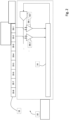
- Fig. 1 shows a schematic diagram of a device 10 according to the invention for determining position or length.
- the device 10 shown serves as an encoder, for example, in a motor feedback system (not shown).
- the device 10 comprises a first part 14, to which an absolute coding 12 is attached.
- the device 10 further comprises a second part 18, to which a reading device 16 is attached.
- the coding 12 and the reading device 16 are attached to the first part 14 and the second part 18 in such a way attached so that they move relative to each other together with the two parts 14 and 18.
- the coding 12 is formed by a plurality of consecutive code sections 22-0 to 22-9 of the first type (shown in white) and the second type (shown in black). Fig. 1 Only ten such code sections 22-0 to 22-9 are shown.
- the coding 12 can include additional code sections to the left and/or right of the illustrated code sections 22-0 to 22-9. This would allow the relative position between the two parts 14 and 18 to be determined over a larger range than would be possible with the ten illustrated code sections 22-0 to 22-9.
- the reading device 16 comprises eight sensors 20-1 to 20-8, for example in the form of photodiodes, wherein the sensors 20-1 to 20-8 are arranged next to one another parallel to the coding 12.
- the sensors 20-1 to 20-8 are aligned with the coding 12 and are designed to detect the different code sections 22-0 to 22-9 of the coding 12.
- a light source (not shown) may be provided, which illuminates at least those code sections 22-0 to 22-9 that lie within the detection range of the sensors 20-1 to 20-8 (the area between the two dashed-double-dotted arrows).
- Each of the sensors 20-1 to 20-8 receives - depending on the type of code sections 22-0 to 22-9 in its detection range - a certain amount of reflected or transmitted light by the respective code sections 22-0 to 22-9.
- Light Sensors 20-1 to 20-8 then output a corresponding measured value, for example in the form of a voltage or current value.
- code sections 22-0 to 22-9 are spatially identical to one another. It is assumed here that the detection range of each sensor 20-1 to 20-8 is half as wide as the individual code sections 22-0 to 22-9 are long. Sensors 20-1 to 20-8 are aligned with coding 12 in such a way that they form a continuous detection range (see the area between the dashed-double-dotted arrows in Fig. 1 ) on the coding 12, the length of which corresponds exactly to the length of a code word of the coding 12. In other words, each code section 22-4 to 22-6, which lies entirely within the detection range of the sensors 20-1 to 20-8, is located in the detection range of at least two, in particular three, adjacent sensors 20-1 to 20-8. This enables particularly fine scanning of the coding 12 and thus a particularly precise resolution of the relative position between the first part 14 and the second part 18.
- each of the sensors 20-1 to 20-8 can be followed by a separate comparator 28-1, 28-2, etc.
- Each of these comparators 28-1, 28-2, etc. can further be connected on the input side to a reference unit REF and can be designed to compare the measurement signal received from the associated sensor 20-1 to 20-8 with a reference signal received from the reference unit REF.
- a comparison signal generated therefrom, in particular a binary one, is then output to the evaluation unit 24 for analysis.
- the measured values are not digitized based on a single fixed threshold value, as is usual, but rather based on a varying threshold value. With a sufficiently rapid variation of the reference signal, each measured value is effectively binarized based on a plurality of different threshold values.
- the evaluation unit 24 can then, based on the corresponding The comparison signal can be used to more accurately reconstruct the specific shape of the measurement signal and thus more accurately determine the positions of the transitions in the detection range of sensors 20-1 to 20-8 as well as the corresponding relative position between the first part and the second part.
- the reference unit generates, in particular, a time-varying, preferably periodically repeating, reference signal.
- an analog measured value from the first sensor 20-1 can be compared with, for example, three different reference values specified by the reference signal. Assume a first measured value is 80% and the three reference values defined by the reference signal are 25%, 50%, and 75%. The comparator 28-1 then outputs a "111" to the evaluation unit 24 as a binarized comparison signal for the first measured value, since the first measured value is higher than all three reference values. From this, the evaluation unit 24 can conclude that the measured value and thus the corresponding coverage is at least 75%.
- the binarized comparison signal would correspond to a "110.” From this, the evaluation unit 24 can conclude that the second measured value and thus the corresponding coverage is between 50% and 75%. This allows the evaluation unit 24 to distinguish between the situations of the two exemplary measurement or coverage values of 80% and 60%. Based on this, the evaluation unit can more precisely determine the positions of the transitions and thus the relative position between the first and second parts. In a conventional design with a fixed comparison value of, for example, 50%, this distinction would not be possible, since the evaluation unit 24 cannot resolve any difference in the binarized signal. The binarized signal would simply display a "1" for both measured values.
- the comparison signal can also be changed continuously, whereby the currently applied comparison signal is determined when the comparator is switched.
- the evaluation unit 24 It is possible to use a predefined periodic reference signal or to have the evaluation unit 24 specify the exact shape of the reference signal in order to be able to determine the positions of the transitions with particular precision, particularly iteratively. Specifically, if the reference signal is controlled by the evaluation unit 24, the evaluation unit 24 could increase the reference value for a binarized value of 1 and decrease the reference value for a binarized value of 0 until the exact measured value is determined with sufficient accuracy. Of course, with such a functionality, it is also conceivable to supply the different comparators with specific reference signals. This makes the evaluation of the measured values more complicated, but also more efficient and accurate.
- the device 10 described here can also be replaced by magnetic, capacitive, or inductive sensors and a corresponding coding 12 as an alternative to optical sensors 20-1 to 20-8 and an optical coding 12.
- a person skilled in the art will also be able to devise numerous modifications and deviations from the described embodiments, which are probably not explicitly described here but nevertheless fall within the scope of the claims.
- Fig. 3 shows an example of absolute coding consisting of code sections of two different types, which are detected by a group of sensors. Transitions 1 to 7 lie between contiguous areas of consecutive code sections of the same type. In the relative position shown, a total of four such transitions (transitions 3, 4, 5, and 6) lie within the detection range of the sensors.
- At least a rough determination of the relative position is possible by identifying the section of the coding currently within the detection range by analyzing the specific sequence of code sections of the first and second type. This rough determination of the relative position is well known and will therefore not be described further.
- a refinement of the determination of the relative position is possible by determining the exact relative position of the transitions within the detection range of the sensors in relation to the individual sensors. Specifically, the measured value of a sensor in whose detection range a corresponding transition lies varies with the respective positioning of the transition along the detection range of the corresponding sensor. In the example from Fig. 3 The sensor not only outputs a brightness value of 0% or 100% as a measured value, but also values between 0% and 100% when a transition occurs within its detection range. An analysis of the sensor's measured values, resolving these intermediate values, allows the relative position between the first and second parts to be determined even more precisely.
- each plurality of correction values can comprise different types of correction values for each sensor.
- One of the correction values can, for example, be a simple position correction value that compensates for an identified variation in the relative position of a sensor relative to the coding and/or to the other sensors. Such a value can, for example, be used to subsequently correct a relative position that has already been determined conventionally. It can also be useful to provide correction values in the form of functions. Such complex correction values then result in different corrections for different situations and/or boundary conditions.
- the correction value can, for example, be a function depending on This means that the specific correction value changes with the temperature.
- Such complex correction values are preferably taken into account when identifying the transitions and/or when initially determining the rough relative position.
- boundary conditions such as fluctuating temperature
- multiple correction tables can be created, each of which is assigned to a specific boundary condition, such as a specific temperature range, or a combination of boundary conditions. This allows the individual correction tables to be kept relatively simple and clear. It is also possible to simply create a new correction table for boundary conditions subsequently identified as relevant, instead of laboriously revising and/or supplementing the remaining correction tables.
- Correction tables that assign at least one correction value to each sensor for each of the transitions it can detect have been identified as particularly advantageous.
- the correction table assigns at least one correction value to each sensor, which depends on a determined rough relative position between the two parts.
- Such a correction value is obviously only suitable for correcting a subsequent fine determination of the relative position.
- a corresponding correction value can appropriately account for stray light occurring at certain transitions along the coding.
- the evaluation unit 24 can have not only read access to the correction table(s), but also write access.
- the evaluation unit 24 can be configured to modify or adapt at least individual correction values based on predetermined patterns. Such patterns can depend on a wide variety of factors. Examples of such factors include the age of the sensors, the total distance traveled by relative movements, external boundary conditions such as temperature, etc. This enables dynamic optimization of the correction values and thus an even more precise determination of the relative position between the two parts.
- the present invention also encompasses a corresponding method for determining position, length, or angle.
- a person skilled in the art can devise numerous modifications and combinations of the described approaches based on the above description and the presented embodiments. Even if not every such modification or combination has been explicitly described, they may nevertheless fall within the scope of the claims.
Landscapes
- Physics & Mathematics (AREA)
- General Physics & Mathematics (AREA)
- Transmission And Conversion Of Sensor Element Output (AREA)
Applications Claiming Priority (1)
| Application Number | Priority Date | Filing Date | Title |
|---|---|---|---|
| DE102023134628.8A DE102023134628A1 (de) | 2023-12-11 | 2023-12-11 | Vorrichtung und verfahren zur positions-, längen- oder winkelbestimmung |
Publications (1)
| Publication Number | Publication Date |
|---|---|
| EP4571267A1 true EP4571267A1 (fr) | 2025-06-18 |
Family
ID=93523066
Family Applications (1)
| Application Number | Title | Priority Date | Filing Date |
|---|---|---|---|
| EP24213108.4A Pending EP4571267A1 (fr) | 2023-12-11 | 2024-11-14 | Dispositif et procédé de détermination de position, de longueur ou d'angle |
Country Status (2)
| Country | Link |
|---|---|
| EP (1) | EP4571267A1 (fr) |
| DE (1) | DE102023134628A1 (fr) |
Citations (3)
| Publication number | Priority date | Publication date | Assignee | Title |
|---|---|---|---|---|
| US4458322A (en) * | 1981-06-19 | 1984-07-03 | Manhattan Engineering Co., Inc. | Control of page storage among three media using a single channel processor program and a page transfer bus |
| WO2013127962A1 (fr) * | 2012-02-29 | 2013-09-06 | Zentrum Mikroelektronik Dresden Ag | Dispositif et procédé pour la détermination de position absolue redondante d'un corps mobile |
| DE112014002505T5 (de) * | 2013-05-21 | 2016-04-28 | Mitsubishi Electric Corporation | Verfahren zum Selbstkalibrieren eines Drehgebers |
Family Cites Families (2)
| Publication number | Priority date | Publication date | Assignee | Title |
|---|---|---|---|---|
| EP2908098B1 (fr) * | 2014-02-18 | 2016-11-30 | Hexagon Technology Center GmbH | Capteur linéaire avec fonctionnalité d'étalonnage |
| EP2908100B1 (fr) * | 2014-02-18 | 2018-01-17 | Hexagon Technology Center GmbH | Système de détermination de positions relatives |
-
2023
- 2023-12-11 DE DE102023134628.8A patent/DE102023134628A1/de active Pending
-
2024
- 2024-11-14 EP EP24213108.4A patent/EP4571267A1/fr active Pending
Patent Citations (3)
| Publication number | Priority date | Publication date | Assignee | Title |
|---|---|---|---|---|
| US4458322A (en) * | 1981-06-19 | 1984-07-03 | Manhattan Engineering Co., Inc. | Control of page storage among three media using a single channel processor program and a page transfer bus |
| WO2013127962A1 (fr) * | 2012-02-29 | 2013-09-06 | Zentrum Mikroelektronik Dresden Ag | Dispositif et procédé pour la détermination de position absolue redondante d'un corps mobile |
| DE112014002505T5 (de) * | 2013-05-21 | 2016-04-28 | Mitsubishi Electric Corporation | Verfahren zum Selbstkalibrieren eines Drehgebers |
Also Published As
| Publication number | Publication date |
|---|---|
| DE102023134628A1 (de) | 2025-06-12 |
Similar Documents
| Publication | Publication Date | Title |
|---|---|---|
| EP0172323B1 (fr) | Appareil de mesure | |
| EP3645440B1 (fr) | Système de détermination de position et procédé de transmission d'une position de cabine d'un ascenseur | |
| DE3688909T2 (de) | Messanordnung mit versetzung. | |
| DE3144334C2 (de) | Wegmeßeinrichtung mit Referenzmarken | |
| EP4242595B1 (fr) | Dispositif et procédé de détermination de position, de longueur ou d'angle | |
| EP0118673B1 (fr) | Dispositif de mesure | |
| EP1403623B2 (fr) | Méthode de détection d'une position absolue | |
| WO2012089366A1 (fr) | Procédé et dispositif pour déterminer un seuil de détection | |
| EP0530176B1 (fr) | Dispositif de mesure linéaire ou angulaire | |
| EP1180665A2 (fr) | Dispositif capteur d'angles de braquage pour véhicules | |
| DE10205691A1 (de) | Verfahren zum Überprüfen der Funktonssicherheit eines Bildsensors sowie Vorrichtung mit einem Bildsensor | |
| EP0895063A1 (fr) | Dispositif de mesure de position | |
| DE102013220747A1 (de) | Maßverkörperung für ein absolutes Positionsmesssystem | |
| EP4571267A1 (fr) | Dispositif et procédé de détermination de position, de longueur ou d'angle | |
| DE3215673C2 (de) | Abtastvorrichtung zum Bestimmen der Konfiguration von Walzgut | |
| DE102023134633B3 (de) | Vorrichtung zur positions-, längen- oder winkelbestimmung | |
| DE3939147A1 (de) | Lichtelektrische positionsmesseinrichtung | |
| DE3917933C2 (fr) | ||
| EP4636361B1 (fr) | Dispositif et procédé de détermination de position, de longueur ou d'angle | |
| DE102023134632A1 (de) | Vorrichtung und verfahren zur positions-, längen- oder winkelbestimmung | |
| DE102023134634B3 (de) | Vorrichtung und verfahren zur positions-, längen- oder winkelbestimmung | |
| DE102023134625B3 (de) | Vorrichtung und verfahren zur positions-, längen- oder winkelbestimmung sowie verfahren zur bildung einer entsprechenden codierung | |
| EP4597042B1 (fr) | Dispositif et procédé de détermination de position, de longueur ou d'angle | |
| EP4597041B1 (fr) | Dispositif et procédé de détermination de position, de longueur ou d'angle | |
| EP4375621B1 (fr) | Dispositif et procédé de détermination de position, de longueur ou d'angle |
Legal Events
| Date | Code | Title | Description |
|---|---|---|---|
| PUAI | Public reference made under article 153(3) epc to a published international application that has entered the european phase |
Free format text: ORIGINAL CODE: 0009012 |
|
| STAA | Information on the status of an ep patent application or granted ep patent |
Free format text: STATUS: THE APPLICATION HAS BEEN PUBLISHED |
|
| AK | Designated contracting states |
Kind code of ref document: A1 Designated state(s): AL AT BE BG CH CY CZ DE DK EE ES FI FR GB GR HR HU IE IS IT LI LT LU LV MC ME MK MT NL NO PL PT RO RS SE SI SK SM TR |
|
| STAA | Information on the status of an ep patent application or granted ep patent |
Free format text: STATUS: REQUEST FOR EXAMINATION WAS MADE |
|
| 17P | Request for examination filed |
Effective date: 20251211 |