EP4571351A1 - Verfahren und vorrichtung zur selbstkalibrierung eines hochfrequenzsenders - Google Patents
Verfahren und vorrichtung zur selbstkalibrierung eines hochfrequenzsenders Download PDFInfo
- Publication number
- EP4571351A1 EP4571351A1 EP23307191.9A EP23307191A EP4571351A1 EP 4571351 A1 EP4571351 A1 EP 4571351A1 EP 23307191 A EP23307191 A EP 23307191A EP 4571351 A1 EP4571351 A1 EP 4571351A1
- Authority
- EP
- European Patent Office
- Prior art keywords
- signal
- modulator
- compensation
- digital signal
- output
- Prior art date
- Legal status (The legal status is an assumption and is not a legal conclusion. Google has not performed a legal analysis and makes no representation as to the accuracy of the status listed.)
- Pending
Links
Images

Classifications
-
- G—PHYSICS
- G01—MEASURING; TESTING
- G01S—RADIO DIRECTION-FINDING; RADIO NAVIGATION; DETERMINING DISTANCE OR VELOCITY BY USE OF RADIO WAVES; LOCATING OR PRESENCE-DETECTING BY USE OF THE REFLECTION OR RERADIATION OF RADIO WAVES; ANALOGOUS ARRANGEMENTS USING OTHER WAVES
- G01S7/00—Details of systems according to groups G01S13/00, G01S15/00, G01S17/00
- G01S7/02—Details of systems according to groups G01S13/00, G01S15/00, G01S17/00 of systems according to group G01S13/00
- G01S7/40—Means for monitoring or calibrating
- G01S7/4004—Means for monitoring or calibrating of parts of a radar system
- G01S7/4017—Means for monitoring or calibrating of parts of a radar system of HF systems
-
- H—ELECTRICITY
- H04—ELECTRIC COMMUNICATION TECHNIQUE
- H04B—TRANSMISSION
- H04B17/00—Monitoring; Testing
- H04B17/10—Monitoring; Testing of transmitters
- H04B17/11—Monitoring; Testing of transmitters for calibration
-
- G—PHYSICS
- G01—MEASURING; TESTING
- G01S—RADIO DIRECTION-FINDING; RADIO NAVIGATION; DETERMINING DISTANCE OR VELOCITY BY USE OF RADIO WAVES; LOCATING OR PRESENCE-DETECTING BY USE OF THE REFLECTION OR RERADIATION OF RADIO WAVES; ANALOGOUS ARRANGEMENTS USING OTHER WAVES
- G01S7/00—Details of systems according to groups G01S13/00, G01S15/00, G01S17/00
- G01S7/02—Details of systems according to groups G01S13/00, G01S15/00, G01S17/00 of systems according to group G01S13/00
- G01S7/35—Details of non-pulse systems
-
- H—ELECTRICITY
- H04—ELECTRIC COMMUNICATION TECHNIQUE
- H04B—TRANSMISSION
- H04B1/00—Details of transmission systems, not covered by a single one of groups H04B3/00 - H04B13/00; Details of transmission systems not characterised by the medium used for transmission
- H04B1/02—Transmitters
- H04B1/04—Circuits
- H04B1/0475—Circuits with means for limiting noise, interference or distortion
-
- H—ELECTRICITY
- H04—ELECTRIC COMMUNICATION TECHNIQUE
- H04B—TRANSMISSION
- H04B1/00—Details of transmission systems, not covered by a single one of groups H04B3/00 - H04B13/00; Details of transmission systems not characterised by the medium used for transmission
- H04B1/62—Details of transmission systems, not covered by a single one of groups H04B3/00 - H04B13/00; Details of transmission systems not characterised by the medium used for transmission for providing a predistortion of the signal in the transmitter and corresponding correction in the receiver, e.g. for improving the signal/noise ratio
-
- H—ELECTRICITY
- H04—ELECTRIC COMMUNICATION TECHNIQUE
- H04B—TRANSMISSION
- H04B1/00—Details of transmission systems, not covered by a single one of groups H04B3/00 - H04B13/00; Details of transmission systems not characterised by the medium used for transmission
- H04B1/02—Transmitters
- H04B1/04—Circuits
- H04B2001/0491—Circuits with frequency synthesizers, frequency converters or modulators
Definitions
- the present specification relates to a method and device for self-calibrating a radiofrequency transmitter.
- it relates to a method and device for improving the accuracy of phase error compensation in a radiofrequency transmitter.
- a key parameter for radiofrequency transmitters for example a radar transmitter, is the phase accuracy from the transmitter.
- Some radar systems for example advanced 77GHz MIMO (multiple-input multiple-output) radar solutions, use an IQ modulator (phase rotator) in the transmitter to shift its phase.
- MIMO radar is used to improve angular resolution and depends on a virtual array antenna created by a combination of transmitters and receivers. When multiple transmitters are used simultaneously, it is necessary to distinguish between them in the radar post processing.
- DDMA Doppler Division Multiple Access
- this is achieved by encoding each transmitter through rotation of its phase, using the 80GHz phase rotator within the transmitter. This results in a small frequency shift in the Doppler spectrum, enabling the transmitters to be distinguished in the Doppler spectrum.
- Transmitter phase accuracy may be degraded by RF impairments (including amplitude and phase imbalance, local oscillator (LO) feedthrough) in the IQ modulator (phase rotator).
- the resulting phase error may degrade the radar detection, in particular by degrading its image rejection.
- non-linearities in the phase rotation may create spurs in the Doppler spectrum when using DDMA modulation, or in the range spectrum when using FDMA modulation. These spurs may appear as ghost targets in the radar processing. Compensation of the non-linearity of the phase rotator may be used to reduce the level of the ghost targets.
- a device comprising:
- IQ modulators such as phase rotators used in radar applications, typically have RF imperfections or non-linearities that degrade the transmission phase accuracy, thereby introducing a phase error, which may in turn result in a ghost target in the processed radar data.
- the RF impairments in an IQ modulator may include gain/amplitude imbalance, phase imbalance, and local oscillator (LO) feedthrough.
- the resulting phase error is a main contributor to degradation of radar image and carrier rejection.
- Compensation of RF phase imperfections or non-linearities in the IQ modulator can be used to improve detection, in particular by reducing the level of ghost targets and improving radar image rejection. Calibration of the IQ modulator through digital predistortion of the IQ modulator baseband input may improve the linearity of the IQ modulator and decrease the probability of a false target.
- the accuracy of the compensation depends on the accuracy of the mechanism for monitoring the phase error.
- the resolution of the DACs commonly used to control the IQ modulator is typically a limiting factor in the optimization of the phase error.
- the resolution of the DACs may be increased by increasing the number of bits of the DAC, this has an impact on the die size and can lead to increased costs.
- Digital delta sigma modulation converts an n-bit digital signal to an m-bit digital signal, where m ⁇ n, modulated in time such that its average value is representative of the input.
- the phase rotator output signal may be measured with higher accuracy, enabling more accurate compensation of the RF impairments. In radar applications, this may increase the radar Doppler spectrum dynamic range.
- the compensation may be performed with a higher number of bits. By improving the accuracy of the compensation, the phase error may be reduced and image rejection may be improved, thereby improving the radar performance.
- the resolution of the DAC may be effectively increased without increasing the DAC number of bits, enabling more accurate compensation of rf impairments.
- the present disclosure enables radar performance to be improved for a given DAC resolution.
- the present disclosure may enable the actual resolution of the DAC to be reduced, thereby reducing the area occupied by the DAC, without compromising performance.
- the present disclosure is applicable to any radiofrequency transmitter including an IQ modulator or phase rotator, in particular any IQ system exhibiting gain or phase imbalance or LO feedthrough.
- the delta-sigma modulator portion comprises:
- Applying sigma delta modulation only to the second part of the digital signal may enable a certain SNR (signal to noise ratio) to be maintained in the band of interest.
- the first part is an integer part and the second part is a fractional part of the digital signal.
- the first part comprises the most significant bits of the digital signal, and the second part comprises the least significant bits of the digital signal. In some embodiments, the first part comprises the same number of bits as the digital-to-analog converter.
- the device is selectively operable in:
- Disabling or bypassing the sigma delta modulator during transmission avoids adding noise to the IQ modulator output signal.
- the characteristic noise shaping due to the sigma delta modulator may be incompatible with the transmission signal in some applications, in particular some radar systems.
- the digital signal generating portion may be configured to generate said digital signal based on the reference phase value and said at least one compensation value output by said compensation control circuitry during calibration.
- the phase error on the transmission may still be reduced due to the improved accuracy of the compensation value(s) obtained during calibration.
- the device further comprises a power amplifier coupled to receive the IQ modulator output signal, the power amplifier being configured to amplify the IQ modulator output signal for output to an antenna.
- the power amplifier may be disabled.
- the compensation control circuitry comprises a power meter coupled to receive the IQ modulator output signal and configured to output a power measurement signal indicative of the power of the IQ modulator output signal, and wherein said at least one compensation value by the compensation control circuitry based on the power measurement signal.
- the compensation control circuitry comprises a low pass filter for removing high frequency noise from the power measurement signal.
- said at least one compensation parameter corresponds to at least one of an amplitude adjustment, a phase offset and a dc offset of the respective digital signal.
- said compensation control circuitry is configured to determine said at least one compensation value based on the IQ modulator output signal by iteratively updating the respective compensation value.
- said compensation control circuitry is configured to determine said at least one compensation value based on the IQ modulator output signal by performing at least one respective binary search.
- the compensation control circuitry is further configured to determine from the IQ modulator output signal a signal component path of the IQ modulator having the highest gain, and wherein said at least one compensation value comprises an amplitude adjustment of the respective digital signal corresponding to the signal component path having the highest gain.
- Said amplitude adjustment may decrease the amplitude of the respective digital signal with respect to a predetermined initial amplitude.
- the amplitude of the respective digital signal used for generating the first analog signal may be reduced with respect to its initial value, while the amplitude of the digital signal used for generating the second analog signal retains its initial value, and vice versa. This may be helpful in avoiding saturating the DAC.
- the or each compensation parameter is stored by said first and/or second circuitry or said digital controller.
- the compensation parameter(s) may be stored in a digital register, a flip-flop, or other memory element.
- a phase error on the IQ modulator output signal is less than or equal to 1 degree.
- a radiofrequency transmitter comprising:
- the radiofrequency transmitter is a radar transmitter.
- a method for self-calibrating an IQ modulator comprising:
- the first digital signal corresponds to A*A comp *cos( ⁇ + ⁇ comp )+DC comp_I where ⁇ is the reference phase value, A is an initial amplitude, and said at least one compensation value comprises A comp , ⁇ comp and DC comp_I , and optionally the second digital signal corresponds to A* sin( ⁇ )+DC comp_Q and said at least one compensation value further comprises the value DC comp_Q .
- the second digital signal corresponds to A*A comp *sin( ⁇ + ⁇ comp )+DC comp_Q where ⁇ is the reference phase value, A is an initial amplitude, and said at least one compensation value comprises the values A comp , ⁇ comp and DC comp_Q, and optionally the first digital signal corresponds to A*cos( ⁇ )+DC comp_I and said at least one compensation value further comprises the value DC comp_I .
- applying sigma-delta modulation to the first/second digital signal comprises:
- determining said at least one compensation value based on the IQ modulator output signal comprises determining said at least one compensation value based on a measurement of the power of the IQ modulator output signal as a function of the phase reference value.
- determining said at least one compensation value based on the IQ modulator output signal comprises averaging or applying a low-pass filter to a measurement of the IQ modulator output signal.
- said at least one compensation value comprises at least one of an amplitude adjustment, a phase offset and a dc offset of the first digital signal.
- said method further comprises:
- said method further comprises storing said at least one compensation value.
- determining said at least one compensation value based on the IQ modulator output signal comprises iteratively updating the respective compensation value.
- determining said at least one compensation value based on the IQ modulator output signal comprises at least one respective binary search.
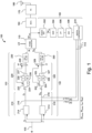
- FIG. 1 schematically illustrates a device 100 according to an example embodiment of this disclosure.
- the device 100 in the form of a radiofrequency transmitter, includes a first input 105 for receiving a reference phase value ⁇ , a phase rotator 110, first circuitry 120, second circuitry 130, compensation control circuitry 150, buffers 160, a power amplifier 170 and a radar antenna 180.
- the radio-frequency phase rotator 110 in the form of an IQ modulator 110, is controlled by a first analog signal A I and a second analog signal A Q , for the I and Q paths respectively.
- the IQ modulator 110 also receives an input signal in the form of a local oscillator signal LO and generates an output signal RF out based on the local oscillator signal LO, the first analog signal A I and the second analog signal A Q .
- the phase of the output signal RF out is controlled by the first and second analog signals A I and A Q .
- FIG. 2 schematically illustrates an example IQ modulator 110 for use in the device 100.
- the input signal LO received by the IQ modulator 110 is split into an in-phase (I) component LOI, which is substantially in phase with the received input signal, and a quadrature-phase (Q) component LOQ, which acquires a phase shift at block 112 so that it is substantially 90 degrees out of phase with the received input signal LO.
- a first mixer 114 receives the in-phase component LOI and the first analog signal A I and outputs a first signal component P I being the product of the in-phase component LOI and the first analog signal A I .
- a second mixer 116 receives the quadrature-phase component LOQ and the second analog signal A Q and outputs a second signal component P Q being the product of the in-phase component LOQ and the first analog signal A Q .
- An adder 118 receives and first and second signal components P I and P Q and outputs the IQ modulator output signal RF out being the sum of the first and second signal components P I and P Q .
- the IQ modulator output signal RF out is coupled via a buffer 160 (for example, a series of buffers) to a power amplifier 170 for amplifying the output signal RF out for output to the radar antenna 180.
- a buffer 160 for example, a series of buffers
- a power amplifier 170 for amplifying the output signal RF out for output to the radar antenna 180.
- the first analog signal A I is generated by the first circuitry 120, which is coupled to the first input 105 for receiving the reference phase value ⁇ and is configured to output a first analog signal A I , based on the reference phase value ⁇ .
- the second analog signal A Q is generated by the second circuitry 130, which is coupled to the first input 105 for receiving said reference phase value ⁇ and is configured to output a second analog signal A Q , based on the reference phase value ⁇ .
- a real IQ modulator 110 has phase and gain imperfections (i.e., phase and gain imbalances), and also LO feedthrough, leading to non-linearities in the behaviour of the IQ modulator 110 which can lead to a phase error at the IQ modulator output signal RF out .
- the compensation control circuitry 150 is used to monitor and compensate the phase error by providing feedback from the output of the power rotator 110 to the first circuitry 120 and/or second circuitry 130, which generate the respective first analog signal A I and second analog signal A Q for controlling the IQ modulator 110.
- the compensation control circuitry 150 is coupled to receive the IQ modulator output signal RF out and is configured to output at least one compensation signal 512 indicative of a compensation value based on the IQ modulator output signal RF out .
- the compensation values are used to pre-distort the analog signals A I , A Q used to control the IQ modulator 110, for example by adjusting an amplitude, phase offset and/or dc offset of one or both of the analog signals A I , A Q . In this way, the device 100 compensates RF imperfections of the IQ modulator 110.
- the amplitude, phase offset and dc offset of each signal may be determined or adjusted by the compensation signals received, by the first and second circuitry 120, 130, from the compensation control circuitry 150.
- the compensation values indicated by the compensation signals 512 output by the compensation control circuitry 150 include an amplitude adjustment A comp and a phase offset ⁇ comp for compensating gain imbalance and phase imbalance respectively, and dc offsets DC comp_I and DC comp_Q for compensating LO feedthrough on the two paths.
- the first circuitry 120 comprises a first digital signal generating portion 210, a first sigma-delta modulation portion 220, and a first digital-to-analog converter (DAC) 230.
- the first digital signal generating portion 210 generates a first digital signal D I corresponding to A 1 *cos( ⁇ + ⁇ 1 ) + DC 1 , based on the reference phase value ⁇ and the compensation values indicated by the compensation signals 512 received from the compensation control circuitry 150.
- the first sigma-delta modulation portion 220 applies sigma-delta modulation to the first digital signal D I .
- the first DAC 230 is coupled to the output of the sigma-delta modulation portion 220 for selectively receiving one of a modulated first digital signal or an unmodulated portion of the first digital signal, and to output the first analog signal A I for controlling the I (in-phase) branch of the IQ modulator 110.
- the first analog signal A I is an analog signal having an amplitude corresponding to the first digital signal.
- the second circuitry 130 comprises a second digital signal generating portion 310, a second sigma-delta modulation portion 320 and a second digital-to-analog converter (DAC) 330.
- the second digital signal generating portion 210 generates a second digital signal D Q corresponding to A 2 *sin( ⁇ + ⁇ 2 ) + DC 2 , based on the reference phase value ⁇ and the compensation values indicated by the compensation signals 512 received from the compensation control circuitry 150.
- the second sigma-delta modulation portion 320 for applies sigma-delta modulation to the second digital signal D Q .
- the second DAC 330 is coupled to the output of the second sigma-delta modulation portion 320 for selectively receiving one of a modulated second digital signal or an unmodulated portion of the second digital signal, and to output the second analog signal A Q for controlling the Q (quadrature-phase) branch of the IQ modulator 110.
- the second analog signal A Q is an analog signal having an amplitude corresponding to the second digital signal.
- Each of the first digital signal generating portion 210 and the second digital signal generating portion 310 comprises a CORDIC 214, 314 for generating A 1 *cos( ⁇ + ⁇ 1 ) and A 2 *sin( ⁇ + ⁇ 2 ) respectively.
- Each CORDIC 214, 314 is coupled to receive as inputs the reference phase value ⁇ and compensation signals 512 indicative of the compensation values A comp (gain imbalance compensation), ⁇ comp (phase imbalance compensation) and path selection control parameters I sel and Q sel , the purpose of which will be described below.
- a LUT look up table
- other means may be used instead of a CORDIC.
- the respective dc offset DC 1 , DC 2 may be applied after the CORDIC, by summing the output of the CORDIC 214, 314 with a signal representing the required offset.
- the first digital signal generating portion 210 comprises a summing node 216 arranged to receive the output of the respective CORDIC 214 and a compensation signal 512 indicative of the compensation value DC comp_I .
- the second digital signal generating portion 310 comprises a summing node 316 arranged to receive the output of the respective CORDIC 314 and a compensation signal 512 indicative of the compensation value DC comp_Q .
- the first delta-sigma modulation portion 220 is configured to split the first digital signal D I into first 222 and second 224 parts, apply delta-sigma modulation to the second part 224 of the first digital signal D I , and sum the modulated second part 224 with the first part 222 of the first digital signal.
- the first delta-sigma modulator portion 220 comprises a delay element 225, a digital sigma-delta modulator 226, a summing node 227 and a mode selector 228.
- the sigma-delta modulator 226 receives the first (e.g., fractional) part 224 of the first digital signal D I and applies sigma-delta modulation to this first part 224.
- the delay element 225 receives the second (e.g., integer) part 222 of the first digital signal D I and applies a delay to this second part 222 equivalent to the delay of the sigma-delta modulator 226.
- the delayed first part output by the delay element 225 is recombined with the sigma-delta modulated second part output by the sigma-delta modulator 226 at the summing node 227.
- the modulated first digital signal output of the sigma-delta modulation portion 220 is therefore a digital signal, of which the most significant bit or bits are unmodulated and the least significant bit or bits are modulated in time.
- the mode control signal cal is ON (e.g., high) and the mode selector 228 outputs the recombined sigma-delta modulated first digital signal to the first DAC 230.
- the mode control signal cal is OFF (e.g., low) and the mode selector 228 outputs the first part 222 of the unmodulated first digital signal D I to the first DAC 230.
- the first DAC 230 therefore selectively receives either the recombined digital signal or the unmodulated first part 222 of the first digital signal D I from the first sigma delta modulation portion 220, depending on the state of the mode control signal cal.
- the second delta-sigma modulator portion 320 is configured to split the second digital signal D Q into first 322 and second 324 parts, apply delta-sigma modulation to the second part 324 of the second digital signal D Q , and sum the modulated second part 324 with the first part 322 of the second digital signal.
- the second delta-sigma modulator portion 320 comprises a delay element 325, a digital sigma-delta modulator 326, a summing node 327 and a mode selector 328.
- the sigma-delta modulator 326 receives the first (e.g., fractional) part 324 of the second digital signal D Q and applies sigma-delta modulation to this first part 324.
- the delay element 325 receives the second (e.g., integer) part 322 of the second digital signal D Q and applies a delay to this second part 322 equivalent to the delay of the sigma-delta modulator 326.
- the delayed first part output by the delay element 325 is recombined with the sigma-delta modulated second part output by the sigma-delta modulator 326 at the summing node 327.
- the mode selector 328 in the form of a multiplexer, is coupled to receive the recombined sigma-delta modulated second digital signal output by the summing node 327, the first part 322 of the unmodulated second digital signal D Q , and the mode control signal cal.
- the mode control signal cal is OFF (e.g., low) and the mode selector 328 outputs the first part 322 of the unmodulated second digital signal D Q to the second DAC 330.
- the second DAC 330 therefore selectively receives either the recombined digital signal or the unmodulated first part 322 of the second digital signal D Q from the second sigma delta modulation portion 320.
- the digital sigma-delta modulators 226, 326 may be provided in the form of a simple MASH (multi-stage noise shaping) structure of order 3 or 4, but other architectures of sigma-delta modulator may be used.
- each of the first and second digital signals D I , D Q comprises n1 bits and each of the first and second DACs 230, 330 is a n2-bit DAC, where n2 ⁇ n1.
- the first part 222, 322 of the respective first and second digital signals D I , D Q comprises n2 bits and the second part 224, 324 comprises n1-n2 bits.
- the first part 222, 322 may be an integer part and the second part 224, 324 may be a fractional part of the respective first/second digital signal.
- the compensation may be applied using a higher number of bits than the DAC resolution. In turn, this enables the IQ modulator output signal to be monitored with greater accuracy, increasing the accuracy of the compensation.
- the input signals to the DACs 230, 330 depend on the mode (calibration or transmission).
- the power amplifier 170 may be disabled so that transmission is not active.
- the noise on the monitored IQ modulator output signal RF out arising from operation of the sigma delta modulators 226, 326 may be mitigated, for example by digital averaging and/or by use of a low pass filter 506.
- the compensation control circuitry 150 comprises a detector 502, an amplifier 504, a low pass filter 506, an analog-to-digital converter (ADC) 508 and a digital controller 510.
- the detector 502 is provided in the form of a power meter 502 for monitoring the power of the signal RF out output by the IQ modulator 110.
- the output power is constant, independent of the applied phase rotation ⁇ .
- the rf imperfections in the IQ modulator 110 result in a variation of the power of the IQ modulator output signal RF out with the reference phase value ⁇ . That is, a variation in the power of the output signal RF out of the IQ modulator 110 is observed when different phase rotations are applied to the RF signal.
- the compensation control circuitry 150 determines the compensation values based on the power measurement signal P out output by the power meter 502, by adjusting the compensation values until the variation of P out is optimized.
- the power meter 502 is coupled to receive the output signal RF out of the IQ modulator 110 and is configured to output a power measurement signal P out indicative of the power of the IQ modulator output signal RF out .
- the power meter 502 may comprise, for example, an RMS detector or a peak power detector.
- the power meter 502 may be configured to measure variations of the power of the IQ modulator output signal RF out .
- the power meter 502 is configured to measure the delta variation of the power of the IQ modulator output signal RF out as a function of the programmed phase value ⁇ .
- the amplifier 504 is coupled to receive the power measurement signal P out output by the power meter 502 and to amplify the power variations measured by the power meter 502.
- the amplifier 504 may be provided in the form of a VGA (variable gain amplifier) so that small power variations can be amplified and re-centred to occupy the full range of the ADC 508, by controlling a variable gain and offset of the amplifier 504.
- the low-pass filter 506 is coupled to the output of the amplifier 504 and is configured to remove the high frequency noise arising from the first and second sigma delta modulators 226, 326. In alternative embodiments, digital averaging may be used instead of the low-pass filter 506 to remove this high-frequency noise, although this would require a longer calibration time.
- the ADC 508 is coupled to receive the output of the low-pass filter 506 and to translate the information to the digital controller 510.
- the digital controller 510 is configured to interpret the information from the ADC 508 and to generate optimum compensation for the amplitude, phase and dc offset of the first and/or second analog signals A I , A Q .
- the compensation values indicated by the compensation signals 512 output by the compensation control circuitry 150 include an amplitude adjustment A comp and a phase offset ⁇ comp for compensating gain imbalance and phase imbalance respectively, and dc offsets DC comp_I and DC comp_Q for compensating LO feedthrough on the two paths.
- the compensation signals 512 also include path selection control parameters I sel and Q sel .
- the power of the IQ modulator output signal RF out is monitored as a function of the reference phase value ⁇ .
- the values of the amplitude A 1 , phase offset ⁇ 1 and/or dc offset DC 1 of the first digital signal D I and/or the amplitude A 2 , phase offset ⁇ 2 and/or dc offset DC 2 of the second digital signal D Q are iteratively updated until the delta variation of the IQ modulator output power is considered as minimum or below a desired upper limit.
- the compensation is applied by modifying the amplitude A 1 , phase offset ⁇ 1 and dc offset DC 1 used for generating the first digital signal D I , and the dc offset DC 2 of the second analog signal D Q .
- compensation is applied to the respective dc offsets DC 1 and DC 2 of the two paths.
- the respective optimum compensation value DC comp_I , DC comp_Q , A comp , ⁇ comp
- the dc offsets are calibrated first, followed by the gain imbalance and the phase imbalance.
- the order in which the above calibrations are performed may be different from the default order (that is, dc offset (path I), then dc offset (path Q), then amplitude adjustment, then phase offset) set out above.
- the first and second digital signals before calibration are:
- the compensation of the gain and phase imbalances may be applied to only one path (I or Q), whereas the dc offset compensation is applied to both I and Q paths.
- the amplitude and phase offset compensation is applied only to the first or I (in-phase) path 120
- the first and second digital signals following calibration are:
- the first and second digital signals following calibration would be:
- the digital controller 510 may be configured to determine to which path (I or Q) the compensation is to be applied. For example, the digital controller 510 may be configured to determine which of the I and Q paths shows the highest gain at the output of the IQ modulator 110, and to select this path only for gain compensation. By applying negative gain adjustment to the path showing the highest gain, saturation of the DAC can be avoided.
- the compensation values DC comp_I , DC comp_Q , A comp , ⁇ comp may be stored by the first and/or second circuitry 120, 130 or by the digital controller 510.
- the compensation values may be stored in a digital register, a flip-flop, or other memory element within the device 100.
- the calibration may be repeated prior to each transmission by the device 100.
- Figure 3 shows a flowchart of a method 600 for self-calibrating an IQ modulator according to an example embodiment.
- the method 600 comprises steps 602 to 608.
- a first digital signal (DI, DQ) is generated, based on a reference phase value ( ⁇ ) and at least one compensation value (A comp , ⁇ comp DC comp_I , DC comp_I ) and a second digital signal (DI, DQ) is generated, based on a reference phase value ( ⁇ ).
- sigma-delta modulation is applied to each of the first and second digital signals (DI, DQ).
- the modulated first digital signal and the modulated second digital signal are converted to a first analog signal and a second analog signal respectively.
- an IQ modulator output signal (RF out ) is generated by the IQ modulator, based on a radiofrequency input signal (LO), said first analog signal (A I ) and said second analog signal (A Q ).
- at least one compensation value (A comp , ⁇ comp DC comp_I , DC comp_I ) is updated, based on the IQ modulator output signal (RF out ).
- the compensation in phase, gain and/or DC offset is performed digitally. That is, the first and second digital signals D I , D Q , are computed through CORDIC (or alternatively through LUT).
- the first and second digital signals D I , D Q can be implemented using a high number of bits during calibration, greater than the number of bits of the respective DACs 230, 330, giving a high accuracy on the compensation.
- the DAC resolution is mainly determined by DAC number of bits, which limits the measurement of the variation in the IQ modulator power measured by the power meter 502.
- the DAC resolution thus introduces an error on the measurement output power by the power meter 502, which does not allow an optimized compensation of the gain and phase parameters.
- this limitation due to the DAC resolution is circumvented by including a digital sigma delta modulator 226, 326 in front of each respective DAC 230, 330.
- This increases the effective DAC resolution during calibration, which in turn increases the accuracy with which the phase error may be estimated and thereby further compensated.
- the device 100 With a better accuracy on the measurement of the error due to the introduction of the sigma delta modulators 226, 326, the device 100 according to the present disclosure enables the optimum compensation to be determined. Even though the sigma-delta modulation is bypassed during transmission, such that the higher resolution compensation is quantified by the lower resolution DAC, the effect of the more accurate compensation is still an improvement relative to the compensation that would be determined in the absence of the sigma-delta modulation.
- a maximum phase error of 1 degree or less can be reached using the device according to the present disclosure. This corresponds to a maximum spurs level of 40dBc after calibration. Even in the worst-case scenario, the phase error Is divided by a factor of 2. Simulations also indicate that the performance of a radar system using an 8-bits DAC system without sigma delta modulation is equivalent to that of a 7-bit DAC system incorporating sigma delta modulation as disclosed above. Accordingly, the present disclosure enables reduction of die area of the device without reducing the performance of the device. For example, the die area would be reduced by a factor of 2 by reducing the resolution of the DACs from 8-bits to 7-bits in combination with introducing the sigma delta modulation as disclosed above.
- the compensation control circuitry 150 of the device 100 of the example embodiment described above with reference to Figure 1 is based on monitoring and reducing variations in the power of the IQ modulator output signal, the skilled person will appreciate that other compensation techniques may be used, while benefitting from the improvement provided by the sigma delta modulation disclosed herein.
- Non-linearities in the IQ modulator output signal may be detected through techniques other than by monitoring power variations as described above.
- the required compensation may be determined by down-mixing the output signal, digitizing the down-mixed signal and analyzing the spectral content of the signal by performing a Fast Fourier Transform on the digitized baseband signal to identify the level of each type of RF impairment through its spectral signature. The compensation values may then be adjusted to optimize the level of each RF impairment.
Landscapes
- Engineering & Computer Science (AREA)
- Computer Networks & Wireless Communication (AREA)
- Signal Processing (AREA)
- Physics & Mathematics (AREA)
- Radar, Positioning & Navigation (AREA)
- Remote Sensing (AREA)
- Electromagnetism (AREA)
- General Physics & Mathematics (AREA)
- Compression, Expansion, Code Conversion, And Decoders (AREA)
- Digital Transmission Methods That Use Modulated Carrier Waves (AREA)
Priority Applications (3)
| Application Number | Priority Date | Filing Date | Title |
|---|---|---|---|
| EP23307191.9A EP4571351A1 (de) | 2023-12-13 | 2023-12-13 | Verfahren und vorrichtung zur selbstkalibrierung eines hochfrequenzsenders |
| US18/960,180 US20250202601A1 (en) | 2023-12-13 | 2024-11-26 | Method and device for self-calibrating a radiofrequency transmitter |
| CN202411824014.5A CN120150855A (zh) | 2023-12-13 | 2024-12-12 | 用于自校准射频发射器的方法和装置 |
Applications Claiming Priority (1)
| Application Number | Priority Date | Filing Date | Title |
|---|---|---|---|
| EP23307191.9A EP4571351A1 (de) | 2023-12-13 | 2023-12-13 | Verfahren und vorrichtung zur selbstkalibrierung eines hochfrequenzsenders |
Publications (1)
| Publication Number | Publication Date |
|---|---|
| EP4571351A1 true EP4571351A1 (de) | 2025-06-18 |
Family
ID=89386301
Family Applications (1)
| Application Number | Title | Priority Date | Filing Date |
|---|---|---|---|
| EP23307191.9A Pending EP4571351A1 (de) | 2023-12-13 | 2023-12-13 | Verfahren und vorrichtung zur selbstkalibrierung eines hochfrequenzsenders |
Country Status (3)
| Country | Link |
|---|---|
| US (1) | US20250202601A1 (de) |
| EP (1) | EP4571351A1 (de) |
| CN (1) | CN120150855A (de) |
Families Citing this family (1)
| Publication number | Priority date | Publication date | Assignee | Title |
|---|---|---|---|---|
| US20250309827A1 (en) * | 2024-03-26 | 2025-10-02 | Silicon Laboratories Inc. | Dc offset calibration in an interdependent quadrature receiver |
Citations (5)
| Publication number | Priority date | Publication date | Assignee | Title |
|---|---|---|---|---|
| US20030095607A1 (en) * | 2001-10-16 | 2003-05-22 | Xinping Huang | System and method for direct transmitter self-calibration |
| US20090033538A1 (en) * | 2007-08-01 | 2009-02-05 | Volker Winkler | Ramp Linearization for FMCW Radar Using Digital Down-Conversion of a Sampled VCO Signal |
| US20100099363A1 (en) * | 2008-10-17 | 2010-04-22 | Texas Instruments Incorporated | Closed loop transmitter iq calibration |
| US20220196796A1 (en) * | 2020-12-21 | 2022-06-23 | Infineon Technologies Ag | System and mmic architecture for coherent multi-chip phased array mimo applications |
| US20220196791A1 (en) * | 2020-12-22 | 2022-06-23 | Nxp Usa, Inc. | Method, device, and radar system |
-
2023
- 2023-12-13 EP EP23307191.9A patent/EP4571351A1/de active Pending
-
2024
- 2024-11-26 US US18/960,180 patent/US20250202601A1/en active Pending
- 2024-12-12 CN CN202411824014.5A patent/CN120150855A/zh active Pending
Patent Citations (5)
| Publication number | Priority date | Publication date | Assignee | Title |
|---|---|---|---|---|
| US20030095607A1 (en) * | 2001-10-16 | 2003-05-22 | Xinping Huang | System and method for direct transmitter self-calibration |
| US20090033538A1 (en) * | 2007-08-01 | 2009-02-05 | Volker Winkler | Ramp Linearization for FMCW Radar Using Digital Down-Conversion of a Sampled VCO Signal |
| US20100099363A1 (en) * | 2008-10-17 | 2010-04-22 | Texas Instruments Incorporated | Closed loop transmitter iq calibration |
| US20220196796A1 (en) * | 2020-12-21 | 2022-06-23 | Infineon Technologies Ag | System and mmic architecture for coherent multi-chip phased array mimo applications |
| US20220196791A1 (en) * | 2020-12-22 | 2022-06-23 | Nxp Usa, Inc. | Method, device, and radar system |
Non-Patent Citations (1)
| Title |
|---|
| KALYONCU ILKER ET AL: "A Phase-Calibration Method for Vector-Sum Phase Shifters Using a Self-Generated LUT", IEEE TRANSACTIONS ON CIRCUITS AND SYSTEMS I: REGULAR PAPERS, IEEE, US, vol. 66, no. 4, 1 April 2019 (2019-04-01), pages 1632 - 1642, XP011715387, ISSN: 1549-8328, [retrieved on 20190315], DOI: 10.1109/TCSI.2018.2885172 * |
Also Published As
| Publication number | Publication date |
|---|---|
| CN120150855A (zh) | 2025-06-13 |
| US20250202601A1 (en) | 2025-06-19 |
Similar Documents
| Publication | Publication Date | Title |
|---|---|---|
| JP5432374B2 (ja) | 無線通信のための高効率送信機 | |
| US7539268B2 (en) | Transmission/reception arrangement and method for reducing nonlinearities in output signals from a transmission/reception arrangement | |
| US20010022532A1 (en) | Phase and amplitude detector and method of determining errors | |
| US7330073B2 (en) | Arbitrary waveform predistortion table generation | |
| EP1217754A1 (de) | Verstärkerschaltung, Radiosender, Verfahren und Verwendung | |
| US9007251B2 (en) | Apparatus and method for converting an analog time domain signal into a digital frequency domain signal, and apparatus and method for converting an analog time domain signal into a digital time domain signal | |
| US11671131B2 (en) | Transmitter circuit, compensation value calibration device and method for calibrating IQ imbalance compensation values | |
| US20140204986A1 (en) | Apparatus and Method for Correcting IQ Imbalance | |
| JP2006527534A (ja) | 送信機により生成された無線通信信号などの振幅および位相特性の調整 | |
| EP1345319A2 (de) | Verfahren und System zur Verminderung von Nichtlinearitäten | |
| US20250202601A1 (en) | Method and device for self-calibrating a radiofrequency transmitter | |
| US12309018B2 (en) | Radio frequency circuit and calibration method therefor | |
| US8472559B2 (en) | Polar transmitter and related signal transmitting method | |
| US11656330B2 (en) | Built in self test transmitter phase calibration | |
| US12224767B2 (en) | Signal processing apparatus for use in optical communication | |
| KR101355381B1 (ko) | I 신호 및 q 신호간의 임밸런스를 감소시키기 위한 수신장치 및 방법, 송신 장치 및 방법 | |
| US8045937B2 (en) | Digital phase feedback for determining phase distortion | |
| US8774316B2 (en) | Transmitter including calibration of an in-phase/quadrature (I/Q) modulator and associated methods | |
| US11796635B2 (en) | Radar transceiver | |
| US12388700B2 (en) | Circuit for correcting amplitude imbalance and phase imbalance | |
| CN113179138A (zh) | 收发器和收发器校准方法 | |
| US11764816B2 (en) | Method and circuit for controlling channel mismatch compensation | |
| US8487799B1 (en) | Calibration for RFDAC | |
| KR100450960B1 (ko) | 디지털 가변 이득 증폭 장치 및 방법 | |
| GB2541379A (en) | Method and system for improving spurious free dynamic range of signal processing systems |
Legal Events
| Date | Code | Title | Description |
|---|---|---|---|
| PUAI | Public reference made under article 153(3) epc to a published international application that has entered the european phase |
Free format text: ORIGINAL CODE: 0009012 |
|
| STAA | Information on the status of an ep patent application or granted ep patent |
Free format text: STATUS: THE APPLICATION HAS BEEN PUBLISHED |
|
| AK | Designated contracting states |
Kind code of ref document: A1 Designated state(s): AL AT BE BG CH CY CZ DE DK EE ES FI FR GB GR HR HU IE IS IT LI LT LU LV MC ME MK MT NL NO PL PT RO RS SE SI SK SM TR |
|
| STAA | Information on the status of an ep patent application or granted ep patent |
Free format text: STATUS: REQUEST FOR EXAMINATION WAS MADE |
|
| 17P | Request for examination filed |
Effective date: 20251218 |