EP4571425A1 - Fixiervorrichtung und bilderzeugungsvorrichtung damit - Google Patents
Fixiervorrichtung und bilderzeugungsvorrichtung damit Download PDFInfo
- Publication number
- EP4571425A1 EP4571425A1 EP24217803.6A EP24217803A EP4571425A1 EP 4571425 A1 EP4571425 A1 EP 4571425A1 EP 24217803 A EP24217803 A EP 24217803A EP 4571425 A1 EP4571425 A1 EP 4571425A1
- Authority
- EP
- European Patent Office
- Prior art keywords
- pressing
- belt
- pair
- fixing
- fixing belt
- Prior art date
- Legal status (The legal status is an assumption and is not a legal conclusion. Google has not performed a legal analysis and makes no representation as to the accuracy of the status listed.)
- Pending
Links
Images




Classifications
-
- G—PHYSICS
- G03—PHOTOGRAPHY; CINEMATOGRAPHY; ANALOGOUS TECHNIQUES USING WAVES OTHER THAN OPTICAL WAVES; ELECTROGRAPHY; HOLOGRAPHY
- G03G—ELECTROGRAPHY; ELECTROPHOTOGRAPHY; MAGNETOGRAPHY
- G03G15/00—Apparatus for electrographic processes using a charge pattern
- G03G15/20—Apparatus for electrographic processes using a charge pattern for fixing, e.g. by using heat
- G03G15/2003—Apparatus for electrographic processes using a charge pattern for fixing, e.g. by using heat using heat
- G03G15/2014—Apparatus for electrographic processes using a charge pattern for fixing, e.g. by using heat using heat using contact heat
- G03G15/2017—Structural details of the fixing unit in general, e.g. cooling means, heat shielding means
- G03G15/2032—Retractable heating or pressure unit
-
- G—PHYSICS
- G03—PHOTOGRAPHY; CINEMATOGRAPHY; ANALOGOUS TECHNIQUES USING WAVES OTHER THAN OPTICAL WAVES; ELECTROGRAPHY; HOLOGRAPHY
- G03G—ELECTROGRAPHY; ELECTROPHOTOGRAPHY; MAGNETOGRAPHY
- G03G15/00—Apparatus for electrographic processes using a charge pattern
- G03G15/20—Apparatus for electrographic processes using a charge pattern for fixing, e.g. by using heat
- G03G15/2003—Apparatus for electrographic processes using a charge pattern for fixing, e.g. by using heat using heat
- G03G15/2014—Apparatus for electrographic processes using a charge pattern for fixing, e.g. by using heat using heat using contact heat
- G03G15/2017—Structural details of the fixing unit in general, e.g. cooling means, heat shielding means
-
- G—PHYSICS
- G03—PHOTOGRAPHY; CINEMATOGRAPHY; ANALOGOUS TECHNIQUES USING WAVES OTHER THAN OPTICAL WAVES; ELECTROGRAPHY; HOLOGRAPHY
- G03G—ELECTROGRAPHY; ELECTROPHOTOGRAPHY; MAGNETOGRAPHY
- G03G15/00—Apparatus for electrographic processes using a charge pattern
- G03G15/20—Apparatus for electrographic processes using a charge pattern for fixing, e.g. by using heat
- G03G15/2003—Apparatus for electrographic processes using a charge pattern for fixing, e.g. by using heat using heat
- G03G15/2014—Apparatus for electrographic processes using a charge pattern for fixing, e.g. by using heat using heat using contact heat
- G03G15/2064—Apparatus for electrographic processes using a charge pattern for fixing, e.g. by using heat using heat using contact heat combined with pressure
-
- G—PHYSICS
- G03—PHOTOGRAPHY; CINEMATOGRAPHY; ANALOGOUS TECHNIQUES USING WAVES OTHER THAN OPTICAL WAVES; ELECTROGRAPHY; HOLOGRAPHY
- G03G—ELECTROGRAPHY; ELECTROPHOTOGRAPHY; MAGNETOGRAPHY
- G03G2215/00—Apparatus for electrophotographic processes
- G03G2215/20—Details of the fixing device or porcess
- G03G2215/2003—Structural features of the fixing device
- G03G2215/2016—Heating belt
- G03G2215/2035—Heating belt the fixing nip having a stationary belt support member opposing a pressure member
Definitions
- the present disclosure relates to fixing devices incorporated in image forming apparatuses such as copiers, printers, facsimile machines, and multifunction peripherals having their functions integrated together, and to image forming apparatuses provided with such a fixing device.
- a fixing device including a fixing member configured with a fixing roller or a fixing belt (a heated rotating member) and a pressing roller (a pressing rotating member) kept in pressed contact with each other.
- This fixing device passes the sheet through a fixing nip portion formed between the fixing roller or the fixing belt and the pressing roller, and heats and presses the toner image to fuse and fix the toner image to the sheet.
- the heated rotating member and the pressing rotating member need to be kept in pressed contact with each other with a predetermined pressure.
- An object of the present disclosure is to provide, for a belt-fixing system, a fixing device that can keep constant the pressure at a fixing nip portion between a fixing belt and a pressing roller with a simple configuration, and to provide an image forming apparatus provided with such a fixing device.
- a fixing device includes an endless fixing belt, a nip forming member, a pressing roller, a housing, a planer heater, a pair of belt holders, and a pressing mechanism, and while the fixing belt and the pressing roller are rotating, the fixing device heats and presses a sheet passing through the fixing nip portion to fuse and fix an unfixed toner image to the sheet.
- the nip forming member is arranged opposite the inner circumferential surface of the fixing belt.
- the pressing roller is kept in pressed contact with the nip forming member through the fixing belt to form a fixing nip portion with the fixing belt.
- the housing houses the fixing belt, the nip forming member, and the pressing roller.
- the planer heater is arranged on the surface of the nip forming member facing the fixing belt, and heats the fixing belt.
- the pair of belt holders holds opposite ends of the fixing belt and of the nip forming member.
- the pressing mechanism adjusts the pressure between the fixing belt and the pressing roller.
- the pressing mechanism has a pair of pressing springs that respectively urge the pair of belt holders in a direction toward the pressing roller, and a pair of pressing plates that are respectively arranged opposite the pair of belt holders and that swing in the direction toward or away from the belt holder.
- the pressing mechanism swings the pressing plate to adjust the urging force of the pressing spring.
- the pressing springs are compression coil springs and their diameter is larger than the length of the planer heater in its width direction, which is the same as the rotation direction of the fixing belt.
- the central axis of the pressing spring is arranged to coincide with a straight line passing through the rotation center of the fixing belt and the rotation center of the pressing roller.
- Fig. 1 is a sectional view showing the internal construction of an image forming apparatus 100 according to an embodiment of the present disclosure.
- a main body of the image forming apparatus 100 here, a color printer
- four image forming portions Pa, Pb, Pc, and Pd are arranged in this order from upstream (the left side in Fig. 1 ) in the conveyance direction.
- the image forming portions Pa to Pd are provided so as to correspond to images of four different colors (yellow, cyan, magenta, and black).
- the image forming portions Pa to Pd form yellow, cyan, magenta, and black images sequentially, each through the processes of electrostatic charging, exposure to light, image development, and image transfer.
- photosensitive drums image carrying member 1a, 1b, 1c, and 1d, which carry visible images (toner images) of the different colors.
- An intermediate transfer belt (intermediate transfer member) 8 that rotates counterclockwise in Fig. 1 by being driven by a belt driving motor (not illustrated) is provided adjacent to the image forming portions Pa to Pd.
- the toner images formed on the photosensitive drums 1a to 1d are, by being primarily transferred sequentially to the intermediate transfer belt 8, which moves while in contact with the photosensitive drums 1a to 1d, overlaid on each other.
- the toner images primarily transferred to the intermediate transfer belt 8 are secondarily transferred by a secondary transfer roller 9 to a transfer sheet P as one example of a recording medium.
- the transfer sheet P having the toner images secondarily transferred to it then has the toner images fixed to it in a fixing device 14 and is then discharged out of the main body of the image forming apparatus 100. While the photosensitive drums 1a to 1d are rotated clockwise in Fig. 1 , an image forming process is performed with respect to the photosensitive drums 1a to 1d.
- the transfer sheets P to which toner images will be secondarily transferred are stored inside a sheet cassette 16 arranged in a lower part of the main body of the image forming apparatus 100.
- the transfer sheet P is conveyed via a sheet feed roller 12 and a pair of registration rollers 13 along a sheet conveyance passage 19 to the nip between the secondary transfer roller 9 and a driving roller 11 for the intermediate transfer belt 8.
- Used as the intermediate transfer belt 8 is a sheet of a dielectric resin, typically a belt with no seam (a seamless belt). Downstream of the secondary transfer roller 9, a blade-form belt cleaner 25 for removing toner and the like left on the surface of the intermediate transfer belt 8 is provided.
- the image forming portions Pa to Pd will be described.
- charging devices 2a, 2b, 2c, and 2d which electrostatically charge the photosensitive drums 1a to 1d
- an exposure device 5 which exposes the photosensitive drums 1a to 1d to light conveying image information
- developing device 3a, 3b, 3c, and 3d which form toner images on the photosensitive drums 1a to 1d
- cleaning devices 7a, 7b, 7c, and 7d which remove developer (toner) and the like left on the photosensitive drums 1a to 1d.
- the charging devices 2a to 2d electrostatically charge the surfaces of the photosensitive drums 1a to 1d uniformly.
- the exposure device 5 irradiates the photosensitive drums 1a to 1d with light according to image data to form on them electrostatic latent images according to the image data.
- the development devices 3a to 3d are loaded with predetermined amounts of two-component developer containing toner of different colors, namely yellow, cyan, magenta, and black respectively.
- toner is supplied from toner containers 4a to 4d to the development devices 3a to 3d.
- the toner in the developer is fed from the development devices 3a to 3d to the photosensitive drums 1a to 1d and electrostatically adhere to them.
- toner images are formed according to the electrostatic latent images formed by exposure to light from the exposure device 5.
- primary transfer rollers 6a to 6d apply an electric field at a predetermined transfer voltage between the primary transfer rollers 6a to 6d and the photosensitive drums 1a to 1d, and thereby the yellow, cyan, magenta, and black toner images on the photosensitive drums 1a to 1d are primarily transferred to the intermediate transfer belt 8. These images are formed with a predetermined positional relationship. After that, in preparation for the subsequent formation of new electrostatic latent images, the toner and the like remaining on the surfaces of photosensitive drums 1a to 1d after primary transfer are removed by cleaning devices 7a to 7d.
- the intermediate transfer belt 8 is wound around a driven roller 10, arranged upstream, and the driving roller 11, arranged downstream. As the driving roller 11 is rotated by the belt driving motor (not illustrated), the intermediate transfer belt 8 starts rotating counterclockwise, and the transfer sheet P is conveyed with predetermined timing from the pair of registration rollers 13 to a secondary transfer nip portion N1 (see Fig. 2 ) between the driving roller 11 and the secondary transfer roller 9 provided next to it. The toner images formed on the intermediate transfer belt 8 are secondarily transferred to the transfer sheet P passing through the secondary transfer nip portion N1.
- the transfer sheet P having the toner images secondarily transferred to it is conveyed to the fixing device 14.
- the fixing device 14 has a fixing belt 14a and a pressing roller 14b (see Fig. 2 for both).
- the fixing belt 14a is heated with a planer heater 43 (see Fig. 8 ).
- the pressing roller 14b is kept in pressed contact with the fixing belt 14a to form a fixing nip N2 (see Fig. 5 ) and applies a rotational driving force to the fixing belt 14a.
- the transfer sheet P conveyed to the fixing device 14 is heated and pressed by the fixing belt 14a and the pressing roller 14b; thus the toner images are fixed to the surface of the transfer sheet P and a predetermined full-color image is formed.
- the transfer sheet P with the full-color image formed on it is conveyed via a pair of fixing discharge rollers 24 (see Fig. 2 ) and then has its conveyance direction switched by a branch portion 15 that branches into a plurality of directions so as to be discharged as it is (or after being diverted to a duplex conveyance passage 20 to have images formed on both sides) to a discharge tray 18 by a pair of discharge rollers 17.
- Fig. 2 is a sectional part view around the sheet conveyance passage 19 and the duplex conveyance passage 20 in the image forming apparatus 100 according to this embodiment.
- An open/close cover 21 constitutes part of a side face 102 of the image forming apparatus 100 and is pivotably supported on a cover shaft 21a provided in the lower part of the main body of the image forming apparatus 100.
- the inner side face of the open/close cover 21 constitutes part of one (outside) of the conveyance faces of the duplex conveyance passage 20.
- the side face of the open/close cover 21 is provided with a grip portion 22.
- the grip portion 22 keeps the open/close cover 21 closed with one end part of the grip portion 22 engaging with engagement pins (not illustrated) provided on a front frame and a rear frame of the main body of the image forming apparatus 100. To open the open/closed cover 21, the grip portion 22 is pivoted to disengage from the engagement pins.
- a conveyance unit 23 Inward of the open/close cover 21 is arranged a conveyance unit 23.
- the conveyance unit 23 is supported on the main body of the image forming apparatus 100 so as to be pivotable about a unit shaft 23a and the conveyance unit 23 constitutes part of the conveyance face of the duplex conveyance passage 20 and the sheet conveyance passage 19.
- the duplex conveyance passage 20 extends between the inner side surface of the open/close cover 21 and the outer side surface of the conveyance unit 23 along the side face 102 of the image forming apparatus 100 in the up-down direction, then curves substantially in a C-shape to join the sheet conveyance passage 19.
- the inner side surface of the conveyance unit 23 is fitted with, in order from upstream (bottom in Fig. 2 ) in the conveyance direction of the transfer sheet P, a one-side roller 13b, which constitutes the pair of registration rollers 13, and the secondary transfer roller 9.
- the duplex conveyance passage 20 is exposed over a wide range.
- the conveyance unit 23 moves away from the main body of the image forming apparatus 100 and the sheet conveyance passage 19 is exposed over a wide range.
- the conveyance unit 23 makes contact with the main body of the image forming apparatus 100, the secondary transfer roller 9 is pressed against the driving roller 11 with the intermediate transfer belt 8 in between to form a secondary transfer nip N1.
- Fig. 3 is a perspective view, as seen from the downstream side (left side in Fig. 2 ) in the discharging direction of the transfer sheet P from the image forming apparatus 100, of the fixing device 14.
- Fig. 4 is a side sectional view of the fixing device 14 as cut at its middle in the longitudinal direction.
- the fixing device 14 has a housing 30, side covers 31a and 31b, and a stay 31c.
- the housing 30 houses the fixing belt 14a and the pressing roller 14b.
- Above the housing 30 is supported one-side (left side in Fig. 2 ) roller 24a constituting the pair of fixing discharge rollers 24.
- the side covers 31a and 31b are fixed to side plates 30a and 30b arranged at the opposite ends of the housing 30 in the longitudinal direction.
- the stay 31c is made of metal and is a plate-form member fixed to the housing 30 along the longitudinal direction.
- a pair of spring brackets 40 are formed, each to support one end (lower end) of a pressing spring 35 (see Fig. 5 ) of a pressing mechanism 32.
- a driving input gear 60 and a depressurizing gear 61 there are arranged a driving input gear 60 and a depressurizing gear 61.
- the driving input gear 60 meshes with a roller driving gear (not illustrated) fixed to a rotation shaft 141 of the pressing roller 14b.
- a rotational driving force is transmitted from a fixing driving motor (not illustrated) via a driving output gear (not illustrated) on the main body of the image forming apparatus 100 to the driving input gear 60
- the pressing roller 14b rotates at a predetermined speed.
- the fixing belt 14a kept in pressed contact with the fixing roller 14b also rotates by following the pressing roller 14b.
- a nip forming member 41 Inside the fixing belt 14a are arranged a nip forming member 41 and a belt guide 42.
- the nip forming member 41 makes contact with the pressing roller 14b via the fixing belt 14a to form a fixing nip portion N2 (see Fig. 5 ) through which the transfer sheet P is inserted.
- the nip forming member 41 is made of a heat-resistant resin such as a liquid crystal polymer or an elastic material such as silicone rubber and an elastomer may be arranged on the surface facing the fixing belt 14a for enhanced sliding properties.
- the belt guide 42 is in the shape of an arc in a sectional view and makes contact with the inner circumferential surface of the fixing belt 14a except on the surface facing the nip forming member 41.
- the belt guide 42 applies a predetermined tension to the fixing belt 14a and holds the fixing belt 14a in the shape of an arc from inside it.
- the belt guide 42 is formed of a metal plate that extends along the axial direction of the fixing belt 14a over substantially the same length as the fixing belt 14a.
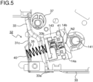
- Fig. 5 is a side sectional view of the fixing device 14 as cut in an end part (a right end part in Fig. 3 ) of it in the longitudinal direction.
- the pressing mechanism 32 is arranged to adjust the pressure between the fixing belt 14a and the pressing roller 14b.
- a pair of pressing mechanisms 32 are provided at the opposite ends of the fixing belt 14a and the pressing roller 14b in the axial direction.
- a pair of pressing mechanisms 32 each have a pressing plate 33, a pressing spring 35, and an eccentric cam 37.
- the pressing spring 35 is a compression coil spring and urges the belt holder 143 in a direction toward the pressing roller 14b. Specifically, one end of the pressing spring 35 is supported in the spring bracket 40 formed in the stay 31c. The other end of the pressing spring 35 is fitted around a second positioning boss 143a (see Fig. 9 ) on the belt holder 143 that projects through a through-hole 33b formed in the pressing plate 33 and is in contact with the pressing plate 33.
- the inner diameter of the through-hole 33b is smaller than the outer diameter of the pressing spring 35 and as the pressing plate 33 swings, the pressing spring 35 expands and contracts between the pressing plate 33 and the spring bracket 40.
- the eccentric cam 37 is arranged at the same side (right side in Fig. 5 ) as the belt holder 143 with respect to the pressing plate 33.
- the eccentric cam 37 is formed integrally with the depressurizing gear 61 (see Fig. 3 ) that feeds the driving force to the pressing mechanism 32.
- the eccentric cam 37 rotates together with the depressurizing gear 61, a change occurs in the outer diameter of the eccentric cam 37 that makes contact with the pressing plate 33.
- Figs. 6 and 7 are side views showing a pressurized state and a depressurized state, respectively, of the pressing mechanism 32.
- the urging force of the pressing spring 35 causes a constant pressure to act on the belt holder 143.
- the pressing roller 14b is kept in pressed contact with the nip forming member 41 to form the fixing nip N2 (see Fig. 5 ) with the fixing belt 14a.
- a light-shielding portion 33c formed on the swinging end of the pressing plate 33 is retracted from a sensing portion of a PI sensor 70 and the PI sensor 70 senses the pressurized state.
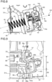
- Fig. 8 is an enlarged part view around the belt holder 143 and the pressing spring 35 in Fig. 5 .
- the pressing spring 35 is arranged on a straight line L passing through the rotation center O1 of the fixing belt 14a and the rotation center O2 of the pressing roller 14b.
- the pressing spring 35 which is a compression coil spring, is arranged so that its center line in the axial direction (contraction direction) of the pressing spring 35 coincides with the straight line L.
- the pressing direction required between the fixing belt 14a and the pressing roller 14b is a direction perpendicular to the fixing nip portion N2 between the fixing belt 14a and the pressing roller 14b, that is, the direction of the straight line L connecting the rotation centers of the fixing belt 14a and the pressing roller 14b.
- Arranging the pressing spring 35 as described above permits the required load (pressure) to be applied in the required pressing direction (the direction of the straight line L). It is thus possible to prevent the variation of the pressure applied by the pressing mechanism 32 and the inclination of the nip forming member 41.
- the planer heater 43 On the nip forming member 41, on its surface facing the pressing roller 14b, the planer heater 43 is arranged.
- the planer heater 43 extends, with a predetermined width R2, over substantially the entire range of the fixing belt 14a along its rotation axis direction (width direction).
- the planer heater 43 is a heating member that heats the fixing belt 14a to a fixing temperature.
- the pressing spring 35 is given a diameter R1 larger than the width R2 of the planer heater 43. It is thus possible to apply the pressure to the planer heater 43 uniformly in the width direction and to prevent the inclination of the planer heater 43 with respect to the fixing nip portion.
- Fig. 9 is a perspective view of the construction around the pressing mechanism 32 as seen from the stay 31c. While Fig. 9 shows the pressing mechanism 32 at one end (right side in Fig. 3 ) of the fixing device 14, the pressing mechanism 32 at the other end (left side in Fig. 3 ) of the fixing device 14 is similarly configured except being symmetrical left to right.
- the spring bracket 40 has formed on it a first positioning boss 40a for positioning one end of the pressing spring 35 (see Fig. 8 ).
- the belt holder 143 has formed on it a second positioning boss 143a for positioning the other end of the pressing spring 35.
- slits 80a and 80b are formed below the spring bracket 40 in the stay 31c.
- the slits 80a and 80b are engaged with a hook portion 81 and a unit positioning projection 82, respectively, on the housing 30.
- the hook portion 81 engages with the slit 80a to couple together the lower end of the stay 31c and the housing 30.
- the unit positioning projection 82 engages with a positioning hole (not illustrated) in the main body of the image forming apparatus 100 when the fixing device 14 is inserted in the main body of the image forming apparatus 100 to position the fixing device 14 relative to the main body of the image forming apparatus 100.
- the stay 31c When the stay 31c is fitted to the housing 30, first, the first positioning boss 40a is inserted in one end of the pressing spring 35. In this state, the slits 80a and 80b are engaged with the hook portion 81 and the unit positioning projection 82 on the housing 30. Then, while the pressing spring 35 is compressed, the stay 31c swung in a direction toward the housing 30 with the lower end of the stay 31c as a fulcrum.
- the spring bracket 40 is provided in the stay 31c of the fixing device 14 and this helps reduce the number of components and assembly man-hours than with the configuration in which the spring bracket 40 is a separate member and thereby reduce the cost of the fixing device 14.
- the distance D1 from the spring bracket 40 (the first positioning boss 40a) to a screw fastening portion 85 is smaller than the distance D2 from the engaging position of the slit 80a with the hook portion 81 to the spring bracket 40 (the first positioning boss 40a).
- the present disclosure is not limited to the above embodiment and can be carried out with any modifications made without departure from the spirit of the present disclosure.
- the slit 80a is provided below the spring bracket 40 in the stay 31c and the hook portion 81 is provided on the housing 30; instead, the hook portion 81 may be provided on the stay 31c and the slit 80a may be provided in the housing 30.
- a color printer as shown in Fig. 1
- the present disclosure is applicable not only to color printers but also to any image forming apparatuses including a fixing device, such as color copiers, color multifunction peripherals, monochrome printers, and monochrome copiers.
- the present disclosure finds applications in fixing devices incorporated in image forming apparatuses such as copiers, printers, facsimile machines, and multifunction peripherals having their functions integrated together. Based on the present disclosure, in a belt-fixing system, it is possible to provide a fixing device that can keep constant the pressure at a fixing nip portion between a fixing belt and a pressing roller with a simple configuration, and to provide an image forming apparatus provided with such a fixing device.
Landscapes
- Physics & Mathematics (AREA)
- General Physics & Mathematics (AREA)
- Fixing For Electrophotography (AREA)
- Electrophotography Configuration And Component (AREA)
Applications Claiming Priority (1)
| Application Number | Priority Date | Filing Date | Title |
|---|---|---|---|
| JP2023209491A JP2025093687A (ja) | 2023-12-12 | 2023-12-12 | 定着装置およびそれを備えた画像形成装置 |
Publications (1)
| Publication Number | Publication Date |
|---|---|
| EP4571425A1 true EP4571425A1 (de) | 2025-06-18 |
Family
ID=93840546
Family Applications (1)
| Application Number | Title | Priority Date | Filing Date |
|---|---|---|---|
| EP24217803.6A Pending EP4571425A1 (de) | 2023-12-12 | 2024-12-05 | Fixiervorrichtung und bilderzeugungsvorrichtung damit |
Country Status (3)
| Country | Link |
|---|---|
| US (1) | US12572096B2 (de) |
| EP (1) | EP4571425A1 (de) |
| JP (1) | JP2025093687A (de) |
Citations (3)
| Publication number | Priority date | Publication date | Assignee | Title |
|---|---|---|---|---|
| US5708926A (en) * | 1993-02-08 | 1998-01-13 | Canon Kabushiki Kaisha | Image heating apparatus with first and second elastic members |
| US20110170919A1 (en) * | 2009-12-28 | 2011-07-14 | Brother Kogyo Kabushiki Kaisha | Fixing Device |
| US20230305457A1 (en) * | 2022-03-22 | 2023-09-28 | Ricoh Company, Ltd. | Fixing device and image forming apparatus |
Family Cites Families (8)
| Publication number | Priority date | Publication date | Assignee | Title |
|---|---|---|---|---|
| JPH06308851A (ja) | 1993-04-19 | 1994-11-04 | Canon Inc | 定着装置 |
| JP4672888B2 (ja) * | 2001-03-09 | 2011-04-20 | キヤノン株式会社 | 定着装置 |
| US10001746B2 (en) * | 2015-05-07 | 2018-06-19 | Canon Kabushiki Kaisha | Image heating apparatus |
| CN108303866B (zh) * | 2017-01-13 | 2021-08-03 | 佳能株式会社 | 定影装置 |
| JP6906972B2 (ja) * | 2017-02-06 | 2021-07-21 | キヤノン株式会社 | 像加熱装置 |
| JP2019028101A (ja) * | 2017-07-25 | 2019-02-21 | キヤノン株式会社 | 加圧ローラ、像加熱装置及び画像形成装置 |
| JP7362304B2 (ja) * | 2019-06-07 | 2023-10-17 | キヤノン株式会社 | 像加熱装置および画像形成装置 |
| JP2025093680A (ja) * | 2023-12-12 | 2025-06-24 | 京セラドキュメントソリューションズ株式会社 | 定着装置およびそれを備えた画像形成装置 |
-
2023
- 2023-12-12 JP JP2023209491A patent/JP2025093687A/ja active Pending
-
2024
- 2024-12-05 US US18/970,134 patent/US12572096B2/en active Active
- 2024-12-05 EP EP24217803.6A patent/EP4571425A1/de active Pending
Patent Citations (3)
| Publication number | Priority date | Publication date | Assignee | Title |
|---|---|---|---|---|
| US5708926A (en) * | 1993-02-08 | 1998-01-13 | Canon Kabushiki Kaisha | Image heating apparatus with first and second elastic members |
| US20110170919A1 (en) * | 2009-12-28 | 2011-07-14 | Brother Kogyo Kabushiki Kaisha | Fixing Device |
| US20230305457A1 (en) * | 2022-03-22 | 2023-09-28 | Ricoh Company, Ltd. | Fixing device and image forming apparatus |
Also Published As
| Publication number | Publication date |
|---|---|
| JP2025093687A (ja) | 2025-06-24 |
| US12572096B2 (en) | 2026-03-10 |
| US20250189911A1 (en) | 2025-06-12 |
Similar Documents
| Publication | Publication Date | Title |
|---|---|---|
| US8244168B2 (en) | Image forming apparatus with movable transfer device | |
| JP4174380B2 (ja) | 電子写真感光体ドラム及びプロセスカートリッジ | |
| US8837989B2 (en) | Belt driving apparatus and image forming apparatus | |
| EP1229406A2 (de) | Kupplungsteil für die photoempfindliche Trommel einer Arbeitseinheit und elektrophotographisches Bilderzeugungsgerät | |
| US9910401B2 (en) | Cartridge and member used for cartridge | |
| US20050220485A1 (en) | Process cartridge and electrophotographic image forming apparatus | |
| JP5081577B2 (ja) | 画像形成装置 | |
| US20100239337A1 (en) | Fixing device and image forming apparatus incorporating same | |
| EP4571424A1 (de) | Fixiervorrichtung und bilderzeugungsvorrichtung damit | |
| US12117764B2 (en) | Toner cartridge | |
| JPH03133871A (ja) | 電子写真装置の定着器 | |
| US12572096B2 (en) | Fixing device that can prevent variation of pressure applied by a pressing roller and inclination of a nip forming member, and image forming apparatus provided therewith | |
| US9804536B2 (en) | Image forming apparatus | |
| JP2008064891A (ja) | 画像形成装置および画像形成方法 | |
| JP2001201976A (ja) | 定着装置及び画像形成装置 | |
| CN107367917A (zh) | 旋转检测机构、定影装置和图像形成装置 | |
| JP7456872B2 (ja) | 用紙分離装置、定着装置、および画像形成装置 | |
| EP2746861B1 (de) | Fixiervorrichtung und Bilderzeugungsvorrichtung | |
| US8792814B2 (en) | Releasing device, fixing device and image forming apparatus | |
| JP2026055086A (ja) | 定着装置 | |
| JP6016094B2 (ja) | 転写装置及び画像形成装置 | |
| JP2002296937A (ja) | ベルト定着装置および画像形成装置 | |
| JP5990794B2 (ja) | 定着装置、及び、画像形成装置 | |
| JP2005156916A (ja) | 画像形成装置 | |
| JP2023174363A (ja) | 定着装置および画像形成装置 |
Legal Events
| Date | Code | Title | Description |
|---|---|---|---|
| PUAI | Public reference made under article 153(3) epc to a published international application that has entered the european phase |
Free format text: ORIGINAL CODE: 0009012 |
|
| STAA | Information on the status of an ep patent application or granted ep patent |
Free format text: STATUS: THE APPLICATION HAS BEEN PUBLISHED |
|
| AK | Designated contracting states |
Kind code of ref document: A1 Designated state(s): AL AT BE BG CH CY CZ DE DK EE ES FI FR GB GR HR HU IE IS IT LI LT LU LV MC ME MK MT NL NO PL PT RO RS SE SI SK SM TR |
|
| STAA | Information on the status of an ep patent application or granted ep patent |
Free format text: STATUS: REQUEST FOR EXAMINATION WAS MADE |
|
| 17P | Request for examination filed |
Effective date: 20250902 |