EP4571704A1 - Procédé permettant de transmettre/recevoir un signal dans un système de communication sans fil et dispositif correspondant - Google Patents
Procédé permettant de transmettre/recevoir un signal dans un système de communication sans fil et dispositif correspondant Download PDFInfo
- Publication number
- EP4571704A1 EP4571704A1 EP23852846.7A EP23852846A EP4571704A1 EP 4571704 A1 EP4571704 A1 EP 4571704A1 EP 23852846 A EP23852846 A EP 23852846A EP 4571704 A1 EP4571704 A1 EP 4571704A1
- Authority
- EP
- European Patent Office
- Prior art keywords
- data
- object detection
- detection
- region
- communication
- Prior art date
- Legal status (The legal status is an assumption and is not a legal conclusion. Google has not performed a legal analysis and makes no representation as to the accuracy of the status listed.)
- Pending
Links
Images







Classifications
-
- G—PHYSICS
- G06—COMPUTING OR CALCULATING; COUNTING
- G06V—IMAGE OR VIDEO RECOGNITION OR UNDERSTANDING
- G06V10/00—Arrangements for image or video recognition or understanding
- G06V10/20—Image preprocessing
- G06V10/25—Determination of region of interest [ROI] or a volume of interest [VOI]
-
- G—PHYSICS
- G06—COMPUTING OR CALCULATING; COUNTING
- G06V—IMAGE OR VIDEO RECOGNITION OR UNDERSTANDING
- G06V10/00—Arrangements for image or video recognition or understanding
- G06V10/20—Image preprocessing
- G06V10/26—Segmentation of patterns in the image field; Cutting or merging of image elements to establish the pattern region, e.g. clustering-based techniques; Detection of occlusion
-
- G—PHYSICS
- G06—COMPUTING OR CALCULATING; COUNTING
- G06V—IMAGE OR VIDEO RECOGNITION OR UNDERSTANDING
- G06V20/00—Scenes; Scene-specific elements
- G06V20/50—Context or environment of the image
- G06V20/52—Surveillance or monitoring of activities, e.g. for recognising suspicious objects
- G06V20/54—Surveillance or monitoring of activities, e.g. for recognising suspicious objects of traffic, e.g. cars on the road, trains or boats
-
- G—PHYSICS
- G06—COMPUTING OR CALCULATING; COUNTING
- G06V—IMAGE OR VIDEO RECOGNITION OR UNDERSTANDING
- G06V20/00—Scenes; Scene-specific elements
- G06V20/50—Context or environment of the image
- G06V20/56—Context or environment of the image exterior to a vehicle by using sensors mounted on the vehicle
- G06V20/58—Recognition of moving objects or obstacles, e.g. vehicles or pedestrians; Recognition of traffic objects, e.g. traffic signs, traffic lights or roads
-
- G—PHYSICS
- G08—SIGNALLING
- G08C—TRANSMISSION SYSTEMS FOR MEASURED VALUES, CONTROL OR SIMILAR SIGNALS
- G08C17/00—Arrangements for transmitting signals characterised by the use of a wireless electrical link
- G08C17/02—Arrangements for transmitting signals characterised by the use of a wireless electrical link using a radio link
-
- G—PHYSICS
- G08—SIGNALLING
- G08G—TRAFFIC CONTROL SYSTEMS
- G08G1/00—Traffic control systems for road vehicles
- G08G1/09—Arrangements for giving variable traffic instructions
- G08G1/0962—Arrangements for giving variable traffic instructions having an indicator mounted inside the vehicle, e.g. giving voice messages
-
- G—PHYSICS
- G08—SIGNALLING
- G08G—TRAFFIC CONTROL SYSTEMS
- G08G1/00—Traffic control systems for road vehicles
- G08G1/16—Anti-collision systems
- G08G1/161—Decentralised systems, e.g. inter-vehicle communication
- G08G1/162—Decentralised systems, e.g. inter-vehicle communication event-triggered
-
- G—PHYSICS
- G08—SIGNALLING
- G08G—TRAFFIC CONTROL SYSTEMS
- G08G1/00—Traffic control systems for road vehicles
- G08G1/16—Anti-collision systems
- G08G1/161—Decentralised systems, e.g. inter-vehicle communication
- G08G1/163—Decentralised systems, e.g. inter-vehicle communication involving continuous checking
-
- G—PHYSICS
- G08—SIGNALLING
- G08G—TRAFFIC CONTROL SYSTEMS
- G08G1/00—Traffic control systems for road vehicles
- G08G1/16—Anti-collision systems
- G08G1/165—Anti-collision systems for passive traffic, e.g. including static obstacles, trees
-
- G—PHYSICS
- G08—SIGNALLING
- G08G—TRAFFIC CONTROL SYSTEMS
- G08G1/00—Traffic control systems for road vehicles
- G08G1/16—Anti-collision systems
- G08G1/166—Anti-collision systems for active traffic, e.g. moving vehicles, pedestrians, bikes
-
- H—ELECTRICITY
- H04—ELECTRIC COMMUNICATION TECHNIQUE
- H04Q—SELECTING
- H04Q9/00—Arrangements in telecontrol or telemetry systems for selectively calling a substation from a main station, in which substation desired apparatus is selected for applying a control signal thereto or for obtaining measured values therefrom
-
- H—ELECTRICITY
- H04—ELECTRIC COMMUNICATION TECHNIQUE
- H04Q—SELECTING
- H04Q2209/00—Arrangements in telecontrol or telemetry systems
- H04Q2209/40—Arrangements in telecontrol or telemetry systems using a wireless architecture
-
- H—ELECTRICITY
- H04—ELECTRIC COMMUNICATION TECHNIQUE
- H04W—WIRELESS COMMUNICATION NETWORKS
- H04W4/00—Services specially adapted for wireless communication networks; Facilities therefor
- H04W4/30—Services specially adapted for particular environments, situations or purposes
- H04W4/40—Services specially adapted for particular environments, situations or purposes for vehicles, e.g. vehicle-to-pedestrians [V2P]
Definitions
- the present disclosure relates to signal transmission and reception in a wireless communication system, and more particularly, to a method of transmitting or receiving signals related to an intelligent transportation system (ITS) and device therefor.
- ITS intelligent transportation system
- Wireless communication systems have been widely deployed to provide various types of communication services such as voice or data.
- a wireless communication system is a multiple access system that supports communication of multiple users by sharing available system resources (a bandwidth, transmission power, etc.).
- multiple access systems include a code division multiple access (CDMA) system, a frequency division multiple access (FDMA) system, a time division multiple access (TDMA) system, an orthogonal frequency division multiple access (OFDMA) system, a single carrier frequency division multiple access (SC-FDMA) system, and a multi carrier frequency division multiple access (MC-FDMA) system.
- CDMA code division multiple access
- FDMA frequency division multiple access
- TDMA time division multiple access
- OFDMA orthogonal frequency division multiple access
- SC-FDMA single carrier frequency division multiple access
- MC-FDMA multi carrier frequency division multiple access
- a sidelink refers to a communication method in which a direct link is established between user equipment (UE), and voice or data is directly exchanged between UEs without going through a base station (BS).
- SL is being considered as one way to solve the burden of the base station due to the rapidly increasing data traffic.
- V2X vehicle-to-everything refers to a communication technology that exchanges information with other vehicles, pedestrians, and infrastructure-built objects through wired/wireless communication.
- V2X may be divided into four types: vehicle-to-vehicle (V2V), vehicle-to-infrastructure (V2I), vehicle-to-network (V2N), and vehicle-to-pedestrian (V2P).
- V2X communication may be provided through a PC5 interface and/or a Uu interface.
- a next-generation radio access technology in consideration of enhanced mobile broadband communication, massive Machine Type Communication (MTC), and Ultra-Reliable and Low Latency Communication (URLLC) may be referred to as new radio access technology (RAT) or new radio (NR).
- RAT new radio access technology
- NR new radio
- V2X vehicle-to-everything
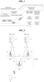
- FIG. 1 is a diagram comparing RAT-based V2X communication before NR with NR-based V2X communication.
- V2X communication in RAT prior to NR, a scheme for providing a safety service based on V2X messages such as a basic safety message (BSM), a cooperative awareness message (CAM), and a decentralized environmental notification message (DENM) was mainly discussed.
- the V2X message may include location information, dynamic information, and attribute information.
- the UE may transmit a periodic message type CAM and/or an event triggered message type DENM to another UE.
- the CAM may include dynamic state information about a vehicle such as direction and speed, vehicle static data such as dimensions, and basic vehicle information such as external lighting conditions and route details.
- a UE may broadcast the CAM, and the CAM latency may be less than 100 ms.
- the UE may generate a DENM and transmit the same to another UE.
- all vehicles within the transmission coverage of the UE may receive the CAM and/or DENM.
- the DENM may have a higher priority than the CAM.
- V2X communication various V2X scenarios have been subsequently introduced in NR.
- the various V2X scenarios may include vehicle platooning, advanced driving, extended sensors, and remote driving.
- vehicles may dynamically form a group and move together. For example, to perform platoon operations based on vehicle platooning, vehicles belonging to the group may receive periodic data from a leading vehicle. For example, the vehicles belonging to the group may reduce or increase the distance between the vehicles based on the periodic data.
- a vehicle may be semi-automated or fully automated. For example, each vehicle may adjust trajectories or maneuvers based on data acquired from local sensors of nearby vehicles and/or nearby logical entities. Also, for example, each vehicle may share driving intention with nearby vehicles.
- raw data or processed data acquired through local sensors, or live video data may be exchanged between a vehicle, a logical entity, UEs of pedestrians and/or a V2X application server.
- the vehicle may recognize an environment that is improved over an environment that may be detected using its own sensor.
- a remote driver or V2X application may operate or control the remote vehicle based on remote driving.
- cloud computing-based driving may be used to operate or control the remote vehicle.
- access to a cloud-based back-end service platform may be considered for remote driving.
- V2X scenarios such as vehicle platooning, advanced driving, extended sensors, and remote driving is being discussed in the NR-based V2X communication field.
- An object of the present disclosure is to provide a method and apparatus for performing data processing related to object detection more accurately and more efficiently in an intelligent transportation system (ITS).
- ITS intelligent transportation system
- a method of transmitting information about object detection by a device in an intelligent transportation system may include segmenting sensor data for objects into a plurality of data subsets, performing object detection for at least one of the plurality of data subsets, and transmitting a message including a result of the object detection.
- a priority related to the object detection may be set for each data subset.
- the device may perform the object detection for a first data subset before a second data subset, based on the first data subset having a higher priority than the second data subset.
- a result of the object detection for the first data subset may be transmitted before a result of the object detection of the second data subset.
- the plurality of data subsets may be related to different physical regions.
- the priority may be determined based on a predefined importance for a corresponding physical region.
- the priority may be determined based on whether vehicle-to-everything (V2X) communication is supported in a corresponding physical region.
- V2X vehicle-to-everything
- the priority may be determined based on V2X communication with an object included in the data subset.
- a data subset for objects capable of exchanging V2X messages with the device may have a higher priority than a data subset for objects not capable of exchanging V2X messages with the device.
- a device may obtain the sensor data for the objects through at least one sensor.
- the sensor data may include an image of the objects.
- the message may be a sensor data sharing message (SDSM) transmitted through wireless communication.
- SDSM sensor data sharing message
- a computer-readable recording medium recording a program for performing the above method may be provided.
- a device operating in an ITS may include a memory storing instructions, and a processor performing operations by executing the instructions.
- the operations of the processor may include segmenting sensor data for objects into a plurality of data subsets, performing object detection for at least one of the plurality of data subsets, and transmitting a message including a result of the object detection.
- a priority related to the object detection may be set for each data subset, and the object detection may be performed for a first data subset before a second data subset, based on the first data subset having a higher priority than the second data subset.
- the device may further include a transceiver transmitting or receiving a wireless signal under the control of the processor.
- the device may be a V2X terminal, a vehicle, or a road side unit (RSU).
- RSU road side unit
- data related to object detection in an intelligent transportation system is processed according to a priority, thereby performing data processing more accurately and more efficiently.
- a sidelink refers to a communication scheme in which a direct link is established between user equipments (UEs) to directly exchange voice or data between UEs without assistance from a base station (BS).
- UEs user equipments
- BS base station
- the sidelink is being considered as one way to address the burden on the BS caused by rapidly increasing data traffic.
- V2X Vehicle-to-everything refers to a communication technology for exchanging information with other vehicles, pedestrians, and infrastructure-built objects through wired/wireless communication.
- V2X may be divided into four types: vehicle-to-vehicle (V2V), vehicle-to-infrastructure (V2I), vehicle-to-network (V2N), and vehicle-to-pedestrian (V2P).
- V2X communication may be provided through a PC5 interface and/or a Uu interface.
- a next-generation radio access technology in consideration of enhanced mobile broadband communication, massive MTC, and Ultra-Reliable and Low Latency Communication (URLLC) may be referred to as new radio access technology (RAT) or new radio (NR).
- RAT new radio access technology
- NR new radio
- CDMA code division multiple access
- FDMA frequency division multiple access
- TDMA time division multiple access
- OFDMA orthogonal frequency division multiple access
- SC-FDMA single carrier-frequency division multiple access
- CDMA may be implemented as a radio technology such as universal terrestrial radio access (UTRA) or CDMA2000.
- TDMA may be implemented as a radio technology such as global system for mobile communications (GSM)/general packet radio service (GPRS)/Enhanced Data Rates for GSM Evolution (EDGE).
- GSM global system for mobile communications
- GPRS general packet radio service
- EDGE Enhanced Data Rates for GSM Evolution
- OFDMA may be implemented as a radio technology such as IEEE 802.11 (Wi-Fi), IEEE 802.16 (WiMAX), IEEE 802.20, evolved-UTRA (E-UTRA) etc.
- UTRA is a part of universal mobile telecommunications system (UMTS).
- 3GPP LTE is a part of Evolved UMTS (E-UMTS) using E-UTRA.
- 3GPP LTE employs OFDMA for downlink and SC-FDMA for uplink.
- LTE-A is an evolution of 3GPP LTE.
- 3GPP NR New Radio or New Radio Access Technology
- 3GPP LTE/LTE-A/LTE-A pro is an evolved version of 3GPP LTE/LTE-A/LTE-A pro.
- 5G NR is a successor technology of LTE-A, and is a new clean-slate mobile communication system with characteristics such as high performance, low latency, and high availability. 5G NR may utilize all available spectrum resources, from low frequency bands below 1 GHz to intermediate frequency bands from 1 GHz to 10 GHz and high frequency (millimeter wave) bands above 24 GHz.
- LTE-A or 5G NR is mainly described, but the technical spirit of the embodiment(s) is not limited thereto
- FIG. 2 illustrates the structure of an LTE system to which the present disclosure is applicable. This may also be called an evolved UMTS terrestrial radio access network (E-UTRAN) or LTE/LTE-A system.
- E-UTRAN evolved UMTS terrestrial radio access network
- LTE/LTE-A system LTE/LTE-A system
- the E-UTRAN includes evolved Node Bs (eNBs) 20 which provide a control plane and a user plane to UEs 10.
- a UE 10 may be fixed or mobile, and may also be referred to as a mobile station (MS), user UE (UT), subscriber station (SS), mobile UE (MT), or wireless device.
- An eNB 20 is a fixed station communication with the UE 10 and may also be referred to as a base station (BS), a base transceiver system (BTS), or an access point.
- BS base station
- BTS base transceiver system
- eNBs 20 may be connected to each other via an X2 interface.
- An eNB 20 is connected to an evolved packet core (EPC) 39 via an S1 interface. More specifically, the eNB 20 is connected to a mobility management entity (MME) via an S1-MME interface and to a serving gateway (S-GW) via an S1-U interface.
- EPC evolved packet core
- MME mobility management entity
- S-GW serving gateway
- the EPC 30 includes an MME, an S-GW, and a packet data network-gateway (P-GW).
- the MME has access information or capability information about UEs, which are mainly used for mobility management of the UEs.
- the S-GW is a gateway having the E-UTRAN as an end point
- the P-GW is a gateway having a packet data network (PDN) as an end point.
- PDN packet data network
- the radio protocol stack between a UE and a network may be divided into Layer 1 (L1), Layer 2 (L2) and Layer 3 (L3). These layers are defined in pairs between a UE and an Evolved UTRAN (E-UTRAN), for data transmission via the Uu interface.
- L1 Layer 1
- L2 Layer 2
- L3 Layer 3
- PHY physical
- RRC radio resource control
- FIG. 3 illustrates the structure of a NR system to which the present disclosure is applicable.
- a next generation radio access network may include a next generation Node B (gNB) and/or an eNB, which provides user-plane and control-plane protocol termination to a UE.
- the NG-RAN is shown as including only gNBs, by way of example.
- a gNB and an eNB are connected to each other via an Xn interface.
- the gNB and the eNB are connected to a 5G core network (5GC) via an NG interface.
- 5GC 5G core network
- the gNB and the eNB are connected to an access and mobility management function (AMF) via an NG-C interface and to a user plane function (UPF) via an NG-U interface.
- AMF access and mobility management function
- UPF user plane function
- FIG. 4 illustrates the structure of a NR radio frame to which the present disclosure is applicable.
- a radio frame may be used for UL transmission and DL transmission in NR.
- a radio frame is 10 ms in length, and may be defined by two 5-ms half-frames.
- An HF may include five 1-ms subframes.
- a subframe may be divided into one or more slots, and the number of slots in an SF may be determined according to a subcarrier spacing (SCS).
- SCS subcarrier spacing
- Each slot may include 12 or 14 OFDM(A) symbols according to a cyclic prefix (CP).
- CP cyclic prefix
- each slot may include 14 symbols, whereas in an extended CP (ECP) case, each slot may include 12 symbols.
- a symbol may be an OFDM symbol (or CP-OFDM symbol) or an SC-FDMA symbol (or DFT-s-OFDM symbol).
- Table 1 lists the number of symbols per slot Nslotsymb, the number of slots per frame Nframe,uslot, and the number of slots per subframe Nsubframe,uslot according to an SCS configuration ⁇ in the NCP case.
- different OFDM(A) numerologies may be configured for a plurality of cells aggregated for one UE.
- the (absolute) duration of a time resource e.g., SF, slot, or TTI
- a time resource is commonly referred to as a time unit (TU) for convenience of description.
- multiple numerologies or SCSs to support various 5G services may be supported. For example, a wide area in conventional cellular bands may be supported when the SCS is 15 kHz, and a dense urban environment, lower latency, and a wider carrier bandwidth may be supported when the SCS is 30 kHz/60 kHz. When the SCS is 60 kHz or higher, a bandwidth wider than 24.25 GHz may be supported to overcome phase noise.
- the NR frequency band may be defined as two types of frequency ranges.
- the two types of frequency ranges may be FR1 and FR2.
- the numerical values of the frequency ranges may be changed.
- the two types of frequency ranges may be configured as shown in Table 3 below.
- FR1 may represent "sub 6 GHz range”
- FR2 may represent "above 6 GHz range” and may be called millimeter wave (mmW).
- mmW millimeter wave
- FR1 may include a band of 410 MHz to 7125 MHz as shown in Table 4 below. That is, FR1 may include a frequency band of 6 GHz (or 5850 MHz, 5900 MHz, 5925 MHz, etc.) or higher.
- the frequency band of 6 GHz (or 5850 MHz, 5900 MHz, 5925 MHz, etc.) or higher included in FR1 may include an unlicensed band.
- the unlicensed band may be used for various purposes, for example, for communication for vehicles (e.g., autonomous driving).
- FIG. 5 illustrates the slot structure of a NR frame to which the present disclosure is applicable.
- one slot includes a plurality of symbols in the time domain.
- one slot may include 14 symbols in a normal CP and 12 symbols in an extended CP.
- one slot may include 7 symbols in the normal CP and 6 symbols in the extended CP.
- a carrier may include a plurality of subcarriers in the frequency domain.
- a resource block (RB) is defined as a plurality of consecutive subcarriers (e.g., 12 subcarriers) in the frequency domain.
- a bandwidth part (BWP) may be defined as a plurality of consecutive (P)RBs in the frequency domain, and the BWP may correspond to one numerology (e.g., SCS, CP length, etc.).
- the carrier may include up to N (e.g., 5) BWPs. Data communication may be conducted in an activated BWP.
- each element may be referred to as a resource element (RE) and may be mapped to one complex symbol.
- RE resource element
- the wireless interface between UEs or the wireless interface between a UE and a network may be composed of an L1 layer, an L2 layer, and an L3 layer.
- the L1 layer may represent a physical layer.
- the L2 layer may represent, for example, at least one of a MAC layer, an RLC layer, a PDCP layer, and an SDAP layer.
- the L3 layer may represent, for example, an RRC layer.
- V2X or sidelink (SL) communication will be described.
- FIG. 6 illustrates a radio protocol architecture for SL communication. Specifically, FIG. 6-(a) shows a user plane protocol stack of NR, and FIG. 6-(b) shows a control plane protocol stack of NR.
- SLSS sidelink synchronization signal
- the SLSS is an SL-specific sequence, and may include a primary sidelink synchronization signal (PSSS) and a secondary sidelink synchronization signal (SSSS).
- PSSS primary sidelink synchronization signal
- SSSS secondary sidelink synchronization signal
- the PSSS may be referred to as a sidelink primary synchronization signal (S-PSS)
- S-SSS sidelink secondary synchronization signal
- S-SSS sidelink secondary synchronization signal
- length-127 M-sequences may be used for the S-PSS
- length-127 gold sequences may be used for the S-SSS.
- the UE may detect an initial signal and acquire synchronization using the S-PSS.
- the UE may acquire detailed synchronization using the S-PSS and the S-SSS, and may detect a synchronization signal ID.
- a physical sidelink broadcast channel may be a (broadcast) channel on which basic (system) information that the UE needs to know first before transmission and reception of an SL signal is transmitted.
- the basic information may include SLSS related information, a duplex mode (DM), time division duplex uplink/downlink (TDD UL/DL) configuration, resource pool related information, the type of an application related to the SLSS, a subframe offset, and broadcast information.
- the payload size of PSBCH in NR V2X may be 56 bits including CRC of 24 bits.
- the S-PSS, S-SSS, and PSBCH may be included in a block format (e.g., an SL synchronization signal (SS)/PSBCH block, hereinafter sidelink-synchronization signal block (S-SSB)) supporting periodic transmission.
- the S-SSB may have the same numerology (i.e., SCS and CP length) as a physical sidelink control channel (PSCCH)/physical sidelink shared channel (PSSCH) in the carrier, and the transmission bandwidth thereof may be within a (pre)set sidelink BWP (SL BWP).
- the bandwidth of the S-SSB may be 11 resource blocks (RBs).
- the PSBCH may span 11 RBs.
- the frequency position of the S-SSB may be (pre)set. Accordingly, the UE does not need to perform hypothesis detection at a frequency to discover the S-SSB in the carrier.
- the transmitting UE may transmit one or more S-SSBs to the receiving UE within one S-SSB transmission period according to the SCS.
- the number of S-SSBs that the transmitting UE transmits to the receiving UE within one S-SSB transmission period may be pre-configured or configured for the transmitting UE.
- the S-SSB transmission period may be 160 ms.
- the S-SSB transmission period of 160 ms may be supported.
- the transmitting UE may transmit one or two S-SSBs to the receiving UE within one S-SSB transmission period. For example, when the SCS is 30 kHz in FR1, the transmitting UE may transmit one or two S-SSBs to the receiving UE within one S-SSB transmission period. For example, when the SCS is 60 kHz in FR1, the transmitting UE may transmit one, two, or four S-SSBs to the receiving UE within one S-SSB transmission period.
- the transmitting UE may transmit 1, 2, 4, 8, 16 or 32 S-SSBs to the receiving UE within one S-SSB transmission period.
- the transmitting UE may transmit 1, 2, 4, 8, 16, 32 or 64 S-SSBs to the receiving UE within one S-SSB transmission period.
- the structure of the S-SSB transmitted from the transmitting UE to the receiving UE may depend on the CP type.
- the CP type may be normal CP (NCP) or extended CP (ECP).
- NCP normal CP
- ECP extended CP
- the number of symbols to which the PSBCH is mapped in the S-SSB transmitted by the transmitting UE may be 9 or 8.
- the number of symbols to which the PSBCH is mapped in the S-SSB transmitted by the transmitting UE may be 7 or 6.
- the PSBCH may be mapped to the first symbol in the S-SSB transmitted by the transmitting UE.
- the receiving UE may perform an automatic gain control (AGC) operation in the period of the first symbol for the S-SSB.
- AGC automatic gain control
- FIG. 7 illustrates UEs performing V2X or SL communication.
- the term UE may mainly refer to a user's UE.
- the BS may also be regarded as a kind of UE.
- UE 1 may be the first device 100
- UE 2 may be the second device 200.
- UE 1 may select a resource unit corresponding to a specific resource in a resource pool, which represents a set of resources. Then, UE 1 may transmit an SL signal through the resource unit.
- UE 2 which is a receiving UE, may receive a configuration of a resource pool in which UE 1 may transmit a signal, and may detect a signal of UE 1 in the resource pool.
- the BS may inform UE 1 of a resource pool.
- another UE may inform UE 1 of the resource pool, or UE 1 may use a preconfigured resource pool.
- the resource pool may be composed of a plurality of resource units, and each UE may select one or multiple resource units and transmit an SL signal through the selected units.
- FIG. 8 illustrates resource units for V2X or SL communication.
- the frequency resources of a resource pool may be divided into NF sets, and the time resources of the resource pool may be divided into NT sets. Accordingly, a total of NF * NT resource units may be defined in the resource pool.
- FIG. 8 shows an exemplary case where the resource pool is repeated with a periodicity of NT subframes.
- one resource unit (e.g., Unit #0) may appear periodically and repeatedly.
- an index of a physical resource unit to which one logical resource unit is mapped may change in a predetermined pattern over time.
- the resource pool may represent a set of resource units available to a UE which intends to transmit an SL signal.
- Resource pools may be subdivided into several types. For example, according to the content in the SL signal transmitted in each resource pool, the resource pools may be divided as follows.
- SA Scheduling assignment
- MCS modulation and coding scheme
- MIMO multiple input multiple output
- TA timing advance
- the SA may be multiplexed with SL data and transmitted through the same resource unit.
- an SA resource pool may represent a resource pool in which SA is multiplexed with SL data and transmitted.
- the SA may be referred to as an SL control channel.
- SL data channel (physical sidelink shared channel (PSSCH)) may be a resource pool through which the transmitting UE transmits user data.
- PSSCH physical sidelink shared channel
- SL data channel may be a resource pool through which the transmitting UE transmits user data.
- the SA and SL data are multiplexed and transmitted together in the same resource unit, only the SL data channel except for the SA information may be transmitted in the resource pool for the SL data channel.
- resource elements (REs) used to transmit the SA information in individual resource units in the SA resource pool may still be used to transmit the SL data in the resource pool of the SL data channel.
- the transmitting UE may map the PSSCH to consecutive PRBs and transmit the same.
- the discovery channel may be a resource pool used for the transmitting UE to transmit information such as the ID thereof. Through this channel, the transmitting UE may allow a neighboring UE to discover the transmitting UE.
- the SL signals described above may use different resource pools according to the transmission/reception properties of the SL signals. For example, even when the SL data channel or discovery message is the same among the signals, it may be classified into different resource pools according to determination of the SL signal transmission timing (e.g., transmission at the reception time of the synchronization reference signal or transmission by applying a predetermined TA at the reception time), a resource allocation scheme (e.g., the BS designates individual signal transmission resources to individual transmitting UEs or individual transmission UEs select individual signal transmission resources within the resource pool), signal format (e.g., the number of symbols occupied by each SL signal in a subframe, or the number of subframes used for transmission of one SL signal), signal strength from a BS, the strength of transmit power of an SL UE, and the like.
- the SL signal transmission timing e.g., transmission at the reception time of the synchronization reference signal or transmission by applying a predetermined TA at the reception time
- a resource allocation scheme e.
- Object detection is a function of, when an input image is given, performing classification and localization for all categories existing in the image.
- This object detection function is installed in a smart CCTV or a smart RSU and used in regions requiring traffic safety, for example, for detecting and identifying moving pedestrians or vehicles through camera sensors, collecting vehicle driving information, or predicting collisions.
- This object recognition function has recently been greatly improved in the performance of image analysis technology such as object and scene recognition due to the recent development of deep learning technology, and most technologies require a structure based on a high-performance GPU server application environment.
- Deep learning-based object detection schemes are largely divided into a two-stage scheme and a single-stage scheme depending on their structures.
- object detection is performed in two stages: a stage for detecting object candidate regions (regions of interest (ROIs)) in an image by selective search and a region proposal network, and a stage for performing class classification and bounding box regression on the detected candidates.
- ROIs region of interest
- a representative two-stage scheme is faster R-CNN.
- the single-stage scheme object detection is performed with a single deep learning model that performs classification and bounding box regression directly from predefined anchor boxes without the stage of detecting object candidate regions.
- methods of the single-stage scheme are mainly used due to operating speed issues, and a representative single-stage scheme is You Only Look Once (YOLO).
- the demand for optimization technology is increasing to reduce response latency because multiple servers are involved in object detection to endpoints, and service performance qualities (low response latency & low detection accuracy vs. high response latency & high detection accuracy) may be categorized according to service purposes so that a customer may select an optimization level.
- a service response based on the server application environment in the C-ITS system is processed largely in three steps: "1. object detection & result analysis delivery, 2. requested service process delivery, and 3. service reception.”
- Table 5 illustrates CCTV- and RSU-related service server-infrastructures. [Table 5] Case# 1. Object Detection & Result Analysis Delivery 2. Requested Service Process Delivery 3.
- V2X message processing is selected from 1) server generation (camera installed) or 2) RSU generation (camera not installed) 3 CCTV shooting/object recognition result video information storage and analysis (cloud) service provision (smartphone) 4 CCTV shooting/object recognition result video system (on-premise server) remote monitoring (smartphone/PC)
- An object detection time may be affected by a function implementation method, the number of objects to be processed, the number of linked server points, and so on. However, as the number of objects to be processed with such attributes and data sizes increases, object detection data processing latency and traffic load will also increase. This may be overcome by optimizing the function implementation method or the number of linked server points, and various technologies are researched and developed to reduce the detection time for optimizing the function implementation method.
- a feature extraction layer which is used as a basic structure for extracting image features in a deep learning model, needs to be lightweight.
- optimization is required from the perspective of a deep learning model structure for object detection or object/scene segmentation.
- a structure for determining the location and type of an object needs to be lightweight
- a structure for segmentation needs to be lightweight.
- a time required for object detection in a typical actual service is 1 second or less, and for example, when video shooting and object recognition detection are processed in the same device, an object recognition detection time for one video frame may be about 200ms.
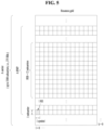
- the object detection function when used in a typical traffic system or C-ITS, the object detection function should output detected data and a detected video, such as FIG. 9 , from which time and physical property information about a detected object are determined, although it depends on an object detection implementation method.
- load factors that should be considered in a service using object detection in a typical ITS may include object detection latency, a detection data processing time, a data size, and a transmission bandwidth.
- the types of data included in detection results may be identified from such an example as FIG. 9 .
- FIG. 10 illustrates an existing server-based object detection structure.
- the object detection latency may be reduced to optimize the function implementation method.
- other load factors a detection data processing time, a data size, and a transmission bandwidth
- the object detection latency has been optimized and improved, compared to the past, but detected data processing, and the transmission, size, and bandwidth of result data for an end user service increase proportionally, thereby increasing system load.
- This load may offset the optimization of the detection latency or may remain.
- This problem may occur when implementing/operating a V2X service using the object detection function based on a server application environment, and may degrade the performance of the service and system.
- the problem may be solved by simple distributed processing using multiple servers and a load balancer (L4 or L7), but with a high cost.
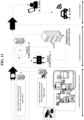
- FIG. 11 illustrates an exemplary object detection structure according to an embodiment.
- structures and operation methods are proposed for distributing a processing process for detecting computing resources based on priority conditions for regions and objects under various conditions in an object detection processing process led/executed by an RSU or a system linked to the RSU in a V2X environment.
- the object detection priority conditions may include whether a V2X message is transmittable/receivable in an object region, the importance of a region object, uniformly segmented regions within an image frame, an important detection region, and whether there is an effective V2X reception region.
- the proposed methods may distribute a processing process and order of computing resources for object detection, thereby reducing load or improving performance.
- an intelligent CCTV or RSU capable of video sensing object detection in an intelligent transportation system (ITS) or cooperative-ITS (C-ITS) processes a moving object detection function in conjunction with a surrounding smart RSU or server
- ITS intelligent transportation system
- C-ITS cooperative-ITS
- objects in a segmented region with priority may be detected by segmenting each processing computing resource, and in the case of object detection using a V2X message, object detection may be performed by segmenting a region and each processing computing resource based on whether information about the location, movement, and state of an acquired object (vehicle, pedestrian, or the like) matches information detected in a region set based on the information.
- object detection may be processed in computing resources divided for corresponding regions according to their priorities.
- object detection based on an effective V2X reception region detection may be performed in the form of a computing resource structure, such that a region, which has been set according to the possibility of existence of an effective V2X reception region based on detection object information for a terrain feature around a moving space by tracking information about the location, movement, and state of an object, is detected first, accompanied by detection of the remaining regions.
- a detecting entity or target system determines that the importance of objects expected to be detected in a corresponding region is low in all of the above object detection situations, it may skip or drop the detection of some objects.
- the detecting entity may perform a detection process by combining two or more of the listed priority conditions.
- an image region may be segmented into uniform regions, and object detection may be processed in each separate computing resource, rather than based on whether V2X information and object detection information match.
- An object detection entity e.g. CCTV, RSU, or the like
- An object detection entity should be able to detect regions with detection priority regardless of whether objects support V2X communication.
- an object supporting V2X communication it should be located in a cover region where it may sense information about the location, movement, and state of an object (e.g. VRU or vehicle) that transmitted a received V2X message, and a specific distance around it.
- the V2X message may be collected through a long-range (e.g. Uu or IF) communication scheme as well as a short-range (e.g. DSRC or PC5) communication scheme, in the cover region.
- a long-range e.g. Uu or IF
- a short-range e.g. DSRC or PC5
- the object detection entity may use a detected location or installed location as a reference point for relative positioning, and when an object is detected from data of a sensor installed in the object detection entity, the relative position of the object may be identified through preset information.
- information about the relative position of the object may be obtained by combining the position of the reference point with the information about the relative position of the object.
- Recognition information and movement attribute information about the object may be detected by comparing the similarity between movement attribute information about the object detected and obtained in this way and movement attribute information about the object received through a V2X message.
- the detection system should be able to detect information about the type, location, size, and direction of the object within an image/video, and the surroundings at a specific distance from the object by combining a detection algorithm of the detection system with relative position information such as the example mentioned above.
- the present disclosure does not specify an object detection technique or algorithm, and proposes a method applicable to a structure that processes object detection based on or linked to an existing server application environment.
- object detection there are two regions, one of which needs to be detected first and the other of which needs to be detected second in a process of searching object candidate regions (ROIs) in an image region according to a distributed processing mode proposed in the disclosure. Accordingly, object detection should be performed by dividing computing resources according to the priorities of required regions.
- an object may not be detected well at a specific point or region in an image, making it meaningless to attempt image detection or generating incorrect detection results.
- an object supporting V2X communication transmits a V2X message at a specific location but is occluded by an obstacle, an (related or matching) image of the object may not be detected for a specific time period.
- the region may be determined as an undetectable region. More specifically, when a specific number (e.g. 100) of or more different objects are detected (or passed) at a specific point or region, and a specific percentage (e.g. 90%) or more of image detection (bounding box generation for an image of a related object) fails, this is recognized as a situation in which image detection is not possible in the region.
- the above point or region information may be collected to form a specific undetectable/excluded region within the coverage region of a camera sensor.
- This undetectable/excluded region may be set to a lowest detection priority, and the detection of the region with the corresponding priority may be skipped or dropped, for processing efficiency.
- This undetectable/excluded region may be partially or wholly changed again to be detectable, when detection obstacles are removed (e.g. structures or terrain features are removed or modified) or for other reasons. This may not be information that is updated in real time over a short period of time, but information that changes over a long period of time. As described above, information about a change in the undetectable/excluded region should be reflected to determine whether to perform detection, a detection priority, and so on. In addition, even in a region which has a very low detection priority and thus is excluded from detection, intermittent detection may be attempted to identify a change, or a detection test may be performed during management or calibration of an RSU CCTV/camera sensor.
- the detection entity or target system may skip or drop the detection of some objects. For example, in the case where it is necessary to continuously track and update information about objects already detected, rather than detecting a specific region, or to maintain detection on the assumption of the same attribute information, when it is determined that an object has a low importance, detection may no longer be performed, or the priority of detection may be lowered for a region where many of these objects are distributed, for the efficiency of the distributed computing structure.
- the message should include physical attribute information (e.g., the position, speed, direction, vehicle length, vehicle width, and so on of a moving vehicle) among essential data fields that should be transmitted.
- physical attribute information e.g., the position, speed, direction, vehicle length, vehicle width, and so on of a moving vehicle
- the physical attribute information may be detected as having the same information values during execution of the object detection function and compared with the information detected from the message to identify a similarity between them.
- the V2X transmitting or receiving terminal refers to a terminal that transmits or receives a message in specific V2X use cases (e.g., basic safety, sensor sharing, maneuver coordination, and so on) including V2X use cases described below.
- V2X use cases e.g., basic safety, sensor sharing, maneuver coordination, and so on
- V2X use cases described below When operating in multiple use cases, even the same terminal may perform a different transmission/reception operation in each use case.
- the similarity between physical attribute information about an object, detected from the two paths of message reception and remote sensing object detection may be analyzed.
- the process proceeds to a detection result data generation & transmission process, whereas when it is determined to be not similar, a re-detection opportunity may be added and a comparison may be performed again.
- an object recognition re-detection opportunity is added every time an error occurs, latency may occur as much, which should also be considered in an overall processing time.
- the object detection time varies depending on the number of detection objects, an applied object detection algorithm, and HW performance.
- the evaluation target detection time set in a research project related to mobile object detection is 200ms, which means that even allowing a few re-detections may be expected to cause a latency of several hundred milliseconds to several seconds.
- a maximum allowed number of times may be changed depending on a latency error value allowed by the given system, and in a situation for increasing a detection accuracy rather than transmitting a detection result in real time, the number of allowed re-detections may be increased within a maximum latency value.
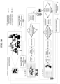
- FIG. 12 is a diagram illustrating a V2X message-based distributed mode.
- V2X message-based distributed mode detection is performed in an object region in which a V2X message is transmittable/receivable with priority, in order to improve the performance of detecting an object supporting V2X communication, and a result is transmitted to a server which will use the detection information. Subsequently, raw data related to the detection and analysis result is transmitted to computing resources that process the detection of the remaining object regions.
- the object detection entity distinguishes a V2X communication supporting object from a non-V2X communication supporting object by determining a matching level between information about the location and movement of an object in a received V2X message and information about a sensed location and movement of the object in an image.
- the object detection entity detects an object supporting V2X communication with priority (1205). Then, the remaining objects determined as non-V2X communication supporting objects in a region are detected through distributed computing resources, and result data is transmitted to the server which will use the result data (1210).
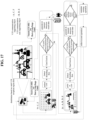
- FIG. 13 is a diagram illustrating an image region-based distributed mode.
- a detection region is segmented to distribute distributed processing for detection as uniformly as possible.
- the details of the image region segmentation method are not specified in the present disclosure, but the image region should be segmented such that objects may be displayed as uniformly as possible. For example, half division or grid division may be used.
- the region is segmented uniformly and a priority is assigned to each region. Then, an object is detected first in a segmented region with a higher priority and a detection result is transmitted to the server which will use the detection information (1305). Subsequently, data related to the detection and analysis result is transmitted to computing resources that process the detection of the remaining object regions. Then, objects in the remaining regions are detected through distributed individual computing resources, and result data is transmitted to the server which will use the result data (1310).
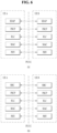
- the object detection entity should be able to perform detection in a detection region, regardless of the number of priority regions and the number of distributed computing resources. For example, among the computing resources that process object detection, an N th system processes a detection region with a highest N th priority, and then an (N+1) th system processes a detection region with an (N+1) th priority. However, in the absence of an (N+2) th system to process an (N+2) th priority region, the (N+1) th system should be able to process both regions with the (N+1) th and (N+2) th priorities.
- This processing order logic may be changed to be optimized according to a server infrastructure resource operation method or an operating environment condition from an implementation perspective, and even when information about an important priority region is changed, it should be reflected in the detection function or process.
- FIG. 14 illustrates such resource distribution in a distributed mode.
- FIG. 15 illustrates an example of an important priority detection region.
- the important detection region include a region 1501 around a road within a specific distance, a region 1502 around an intersection entry direction, a region 1503 within a specific distance from the center of an intersection, a region 1505 around a bicycle road, a blind spot 1504 in a specific direction, an accident-prone region (not shown), and a lane merging/branching section (not shown), which are places where information needs to be collected primarily within a range requiring detection.
- the important detection region may be set and updated based on an actual traffic volume, a traffic trajectory, and the frequency of accident/emergency situations.
- the objects detected in the high-priority important region may be tracked first, just as the objects in the high-priority important region are detected first.
- the tracking of the detected objects may be performed later or may be skipped or dropped.
- FIG. 16 is a diagram illustrating an important region-based distributed mode.
- FIG. 16 illustrates a process of detecting a region, for example, objects within a specific distance of the center of an intersection in an image frame.
- computing resources should be distributed in order based on important detection region information, so that detected objects may be processed, and an exemplary computing resource allocation processing process in the uniformly segmented image region-based distributed mode illustrated in FIG. 14 may also be applied in the same manner.
- a basic configuration and operation method for processing important region-based object detection in a distributed manner should include operations described in Table 6 below.
- Table 6 illustrates an object detection distributed computing operation method on an important region priority basis. [Table 6] # Entity Important Region-based Distributed Mode 1 Object detection entity (CCTV, 1.
- a region that is irrelevant to a user supporting V2X functions within a specific important region there may also be a region that is irrelevant to a user supporting V2X functions within a specific important region. For example, in a basic safety-related use case in which a dangerous situation may be recognized and a user may be warned by receiving BSM and PSM information, there is no need to receive a message from an object existing in a range irrelevant to the safety of a user from which a V2X message is received, or a message for an event that has occurred in the range. Therefore, it may be more useful to perform detection first for regions that are relevant to V2X users, that is, regions within a valid reception range of V2X users.
- FIG. 17 illustrates an example of performing detection for a valid V2X reception region first.
- a priority detection region e.g., a region with high risk factors in an expected movement path and surrounding region of a V2X terminal
- a later detection region or a region for which detection is to be dropped/skipped e.g., a region where a V2X terminal has already passed, or a region with very low or no risk factors in terms of movement speed, direction, and time to collision (TTC) in an expected movement path and surrounding region of the V2X terminal
- TTC time to collision
- Detection may also be performed first for a region corresponding to a valid transmission range of V2X users in the same or similar manner.
- an RSU sensor may need to preferentially detect objects within an effective transmission range of V2X transmitting terminals, and there is no need to preferentially perform detection for a path or region that has already been passed.
- a specific V2X terminal may become a transmitting terminal or a receiving terminal depending on a message transmission/reception state. Accordingly, in the case where a specific terminal may be a transmitting terminal/receiving terminal depending on the situation or where mutual message exchange is required between terminals, a priority detection region may be set by considering an effective transmission range and an effective reception range of each terminal, selectively or both. For example, when terminal 1 is in a transmitting state and terminal 2 is in a receiving state, the effective transmitting range (i.e. range 1) of terminal 1 and the effective receiving range (i.e. range 2) of terminal 2 may be considered. Herein, terminal 2 may be in range 1 and terminal 1 may be in range 2. Generally, when terminals 1 and 2 have the same terminal capability (e.g., may perform a specific use case of Day-2 advanced safety) and the same main parameters (e.g., bandwidth and transmission power), range 1 and range 2 may be the same.
- the same terminal capability e.g., may perform a specific use case of Day-2 advanced
- a valid V2X service region is to be set by tracking based on information which has been detected by using an algorithm or a transmitted V2X message to detect a valid region of objects, detection is to be performed by determining whether to perform detection, and a result is to be transmitted to a server which will use the detection information. For example, when the location of a tracked object is in a region where detection is unnecessary, or when there are no objects to receive a V2X message transmitted by the object, it should be possible to determine that it is invalid and end the detection process or detect the validity of another object. Subsequently, the function of transmitting data related to a detection and analysis result to computing resources that process detection in the remaining object regions is performed.
- a 1 st detection entity may operate to maintain the connectivity of a valid region by transmitting information about the remaining object regions or a valid region with the next priority according to its determination.
- the detection process is performed for objects in the remaining regions or the valid region with the next priority through distributed individual computing resources, and result data is transmitted to the server which will use it.
- the above proposed structure that processes detection based on a priority condition using sensing & V2X message fusion, a uniformly segmented image region-based priority, an important detection region information-based priority, or a valid V2X reception region-based priority may also be applied in various ways by combining two or more priorities.
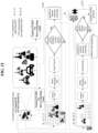
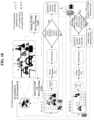
- FIG. 18 illustrates an operation of a distributed mode based on a priority combination - V2X message & uniform image region.
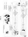
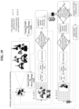
- FIG. 19 illustrates an operation of a distributed mode based on a priority combination - uniform image region & V2X message.
- a mutually complementary distributed processing structure may be created by combining a V2X message supportable object region condition and a uniform image region condition.
- a detection process is started in the V2X message-based distributed mode, and results are identified using computing resources for detecting each object.
- a threshold e.g. 20
- a specific threshold e.g. 80%
- the percentage difference between the two values continues to be equal to or greater than the threshold, it means that the number of objects capable of using V2X service is very small relative to the number of non-supporting objects, or the number of non-supporting objects is very large relative to the number of V2X communication-supporting objects. Therefore, the image region segmentation-based mode is maintained. However, when this difference decreases to or below the threshold, the sensing-V2X message fusion-based mode is switched to, for processing.
- the above percentage difference is based on dividing an absolute difference by an average, and the order of the two values that are calculated is not important in the percentage error.
- a basic configuration and operation method for processing object detection in a distributed manner based on this priority combination may include operations described in Table 7 below.
- Table 7 illustrates an operation method of a distributed mode based on a priority combination (V2X message & image region).
- # Entity V2X message-based distributed mode Image region-based distributed mode 1 Object detection entity (CCTV, RSU, etc.) 1.
- search UE & Non-UE object candidate regions (ROIs) 2.
- Perform class classification and bounding box regression on detected candidates 2.
- Perform class classification and bounding box regression on detected candidates 3. Determine whether movement information in received V2X transmission message of UE matches UE image 3.
- search UE&NorMJE object candidate regions ROIs 7. Perform class classification and bounding box regression on detected candidates 7. Perform class classification and bounding box regression on detected candidates 8. Generate & transmit Non-UE detection result data 8. Determine whether movement information in received V2X transmission message of UE matches UE image 9. Compare percentage difference between the number of detected UEs and the number of detected Non-UEs. If it is equal to or greater than specific ratio, switch to region distributed mode, and if it is equal to or less than specific ratio, maintain the mode. 9.
- segmented region object detection may be restarted 10. Compare percentage difference between the number of detected UEs and the number of detected Non-UEs. If it is equal to or greater than specific ratio, switch to server distributed mode, and if it is equal to or less than specific ratio, maintain the mode. 2 Object detection entity (CCTV, RSU, etc.) 1. transmit received V2X transmission message of UE and video image, and request UE object detection Distribut ed server-A The same as processing process of object detection entity of #1 Distribut ed server -B The same as processing process of object distributed server of #1
- the disclosure has proposed a structure and method for distributing and balancing the load of object detection based on object detection priority conditions using a small number of computing resources. Therefore, a service that is easy to maintain at a low cost may be implemented.
- the disclosure has proposed a structure and operation method for distributing a process of processing computing resources for detection based on priority conditions for regions and objects of various conditions in an object detection processing process led/executed by an RSU or its associated system in a V2X environment.
- the object detection priority conditions for various purposes may include whether a V2X message is transmittable/receivable in an object region, the importance of a region object, uniformly segmented regions within an image frame, an important detection region, and the presence or absence of a valid V2X reception region.
- objects may be detected in a segmented region with priority by distinguishing each processing computing resource.
- detection may be performed by distinguishing a region and each processing computing resource, based on whether information about the location, movement, and state of an obtained object (vehicle or pedestrian) matches information detected in a region set based on the information.
- object detection may be processed in each distinguished computing resource according to the priorities of regions.
- detection may be performed separately in a computing resource structure such that a region, which has been set based on whether a valid V2X reception region exists based on object information detected from the terrain around a movement space by tracking information about the location, movement, and state of an object, is detected first, accompanied by processing of the remaining regions.
- the entity or target system performing detection determines that the importance of objects expected to be detected in a corresponding region is low for all of the above object detection situations, it may skip or drop the detection of some objects.
- the detection process may be performed by combining two or more of the listed priority conditions to improve the object detection processing efficiency of computing resources based on determination of a situation/condition in which the entity performing detection is placed.
- object detection may be processed in each divided computing resource by segmenting an image region into equal regions, rather than whether V2X information matches object detection information.
- FIG. 20 is a flowchart illustrating a method of transmitting information about object detection by a device in an ITS according to one embodiment.
- the device may segment sensor data for objects into a plurality of data subsets (C05).
- the device may perform object detection for at least one of the plurality of data subsets (C10).
- the device may transmit a message including a result of the object detection (C15).
- a priority related to the object detection may be set for each data subset.
- the device may perform object detection for a first data subset before a second data subset, based on the first data subset having a higher priority than the second data subset.
- a result of the object detection for the first data subset may be transmitted before that of the second data subset.
- the plurality of data subsets may be related to different physical regions.
- the priority may be determined based on a predefined importance for a corresponding physical region.
- the priority may be determined based on whether V2X communication is supported in the physical region.
- the priority may be determined based on V2X communication with an object included in the corresponding data subset.
- a data subset for objects capable of exchanging V2X messages with the device may have a higher priority than a data subset for objects not capable of exchanging V2X messages with the device.
- the device may obtain sensor data for the objects through at least one sensor.
- the sensor data may include an image of the objects.
- the message may be a sensor data sharing message (SDSM) transmitted through wireless communication.
- SDSM sensor data sharing message
- FIG. 21 illustrates a communication system applied to the present disclosure.
- a communication system 1 applied to the present disclosure includes wireless devices, Base Stations (BSs), and a network.
- the wireless devices represent devices performing communication using Radio Access Technology (RAT) (e.g., 5G New RAT (NR)) or Long-Term Evolution (LTE)) and may be referred to as communication/radio/5G devices.
- RAT Radio Access Technology
- the wireless devices may include, without being limited to, a robot 100a, vehicles 100b-1 and 100b-2, an eXtended Reality (XR) device 100c, a hand-held device 100d, a home appliance 100e, an Internet of Things (IoT) device 100f, and an Artificial Intelligence (AI) device/server 400.
- RAT Radio Access Technology
- NR 5G New RAT
- LTE Long-Term Evolution
- the wireless devices may include, without being limited to, a robot 100a, vehicles 100b-1 and 100b-2, an eXtended Reality (XR) device 100c, a hand-held device 100d, a home appliance 100
- the vehicles may include a vehicle having a wireless communication function, an autonomous driving vehicle, and a vehicle capable of performing communication between vehicles.
- the vehicles may include an Unmanned Aerial Vehicle (UAV) (e.g., a drone).
- UAV Unmanned Aerial Vehicle
- the XR device may include an Augmented Reality (AR)/Virtual Reality (VR)/Mixed Reality (MR) device and may be implemented in the form of a Head-Mounted Device (HMD), a Head-Up Display (HUD) mounted in a vehicle, a television, a smartphone, a computer, a wearable device, a home appliance device, a digital signage, a vehicle, a robot, etc.
- the hand-held device may include a smartphone, a smartpad, a wearable device (e.g., a smartwatch or a smartglasses), and a computer (e.g., a notebook).
- the home appliance may include a TV, a refrigerator, and a washing machine.
- the IoT device may include a sensor and a smartmeter.
- the BSs and the network may be implemented as wireless devices and a specific wireless device 200a may operate as a BS/network node with respect to other wireless devices.
- the wireless devices 100a to 100f may be connected to the network 300 via the BSs 200.
- An AI technology may be applied to the wireless devices 100a to 100f and the wireless devices 100a to 100f may be connected to the AI server 400 via the network 300.
- the network 300 may be configured using a 3G network, a 4G (e.g., LTE) network, or a 5G (e.g., NR) network.
- the wireless devices 100a to 100f may communicate with each other through the BSs 200/network 300, the wireless devices 100a to 100f may perform direct communication (e.g., sidelink communication) with each other without passing through the BSs/network.
- the vehicles 100b-1 and 100b-2 may perform direct communication (e.g.
- V2V Vehicle-to-Vehicle
- V2X Vehicle-to-everything
- Wireless communication/connections 150a, 150b, or 150c may be established between the wireless devices 100a to 100f/BS 200, or BS 200/BS 200.
- the wireless communication/connections may be established through various RATs (e.g., 5G NR) such as uplink/downlink communication 150a, sidelink communication 150b (or, D2D communication), or inter BS communication (e.g. relay, Integrated Access Backhaul (IAB)).
- the wireless devices and the BSs/the wireless devices may transmit/receive radio signals to/from each other through the wireless communication/connections 150a and 150b.
- the wireless communication/connections 150a and 150b may transmit/receive signals through various physical channels.
- various configuration information configuring processes various signal processing processes (e.g., channel encoding/decoding, modulation/demodulation, and resource mapping/demapping), and resource allocating processes, for transmitting/receiving radio signals, may be performed based on the various proposals of the present disclosure.
- various signal processing processes e.g., channel encoding/decoding, modulation/demodulation, and resource mapping/demapping
- resource allocating processes for transmitting/receiving radio signals
- FIG. 22 illustrates a wireless device applicable to the present disclosure.
- a first wireless device 100 and a second wireless device 200 may transmit radio signals through a variety of RATs (e.g., LTE and NR).
- ⁇ the first wireless device 100 and the second wireless device 200 ⁇ may correspond to ⁇ the wireless device 100x and the BS 200 ⁇ and/or ⁇ the wireless device 100x and the wireless device 100x ⁇ of FIG. 21 .
- the first wireless device 100 may include one or more processors 102 and one or more memories 104 and additionally further include one or more transceivers 106 and/or one or more antennas 108.
- the processor(s) 102 may control the memory(s) 104 and/or the transceiver(s) 106 and may be configured to implement the descriptions, functions, procedures, proposals, methods, and/or operational flowcharts disclosed in this document.
- the processor(s) 102 may process information within the memory(s) 104 to generate first information/signals and then transmit radio signals including the first information/signals through the transceiver(s) 106.
- the processor(s) 102 may receive radio signals including second information/signals through the transceiver 106 and then store information acquired by processing the second information/signals in the memory(s) 104.
- the memory(s) 104 may be connected to the processor(s) 102 and may store a variety of information related to operations of the processor(s) 102.
- the memory(s) 104 may store software code including commands for performing a part or the entirety of processes controlled by the processor(s) 102 or for performing the descriptions, functions, procedures, proposals, methods, and/or operational flowcharts disclosed in this document.
- the processor(s) 102 and the memory(s) 104 may be a part of a communication modem/circuit/chip designed to implement RAT (e.g., LTE or NR).
- the transceiver(s) 106 may be connected to the processor(s) 102 and transmit and/or receive radio signals through one or more antennas 108.
- Each of the transceiver(s) 106 may include a transmitter and/or a receiver.
- the transceiver(s) 106 may be interchangeably used with Radio Frequency (RF) unit(s).
- the wireless device may represent a communication modem/circuit/chip.
- a UE may include the processor(s) 102 connected to the RF transceiver and the memory(s) 104.
- the memory(s) 104 may include at least one program for performing operations related to the embodiments described above with reference to FIGS. 11 to 27.
- a chipset including the processor(s) 102 and memory(s) 104 may be configured.
- the chipset may include: at least one processor; and at least one memory operably connected to the at least one processor and configured to, when executed, cause the at least one processor to perform operations.
- the second wireless device 200 may include one or more processors 202 and one or more memories 204 and additionally further include one or more transceivers 206 and/or one or more antennas 208.
- the processor(s) 202 may control the memory(s) 204 and/or the transceiver(s) 206 and may be configured to implement the descriptions, functions, procedures, proposals, methods, and/or operational flowcharts disclosed in this document.
- the processor(s) 202 may process information within the memory(s) 204 to generate third information/signals and then transmit radio signals including the third information/signals through the transceiver(s) 206.
- the processor(s) 202 may receive radio signals including fourth information/signals through the transceiver(s) 106 and then store information acquired by processing the fourth information/signals in the memory(s) 204.
- the memory(s) 204 may be connected to the processor(s) 202 and may store a variety of information related to operations of the processor(s) 202.
- the memory(s) 204 may store software code including commands for performing a part or the entirety of processes controlled by the processor(s) 202 or for performing the descriptions, functions, procedures, proposals, methods, and/or operational flowcharts disclosed in this document.
- the processor(s) 202 and the memory(s) 204 may be a part of a communication modem/circuit/chip designed to implement RAT (e.g., LTE or NR).
- the transceiver(s) 206 may be connected to the processor(s) 202 and transmit and/or receive radio signals through one or more antennas 208.
- Each of the transceiver(s) 206 may include a transmitter and/or a receiver.
- the transceiver(s) 206 may be interchangeably used with RF unit(s).
- the wireless device may represent a communication modem/circuit/chip.
- One or more protocol layers may be implemented by, without being limited to, one or more processors 102 and 202.
- the one or more processors 102 and 202 may implement one or more layers (e.g., functional layers such as PHY, MAC, RLC, PDCP, RRC, and SDAP).
- the one or more processors 102 and 202 may generate one or more Protocol Data Units (PDUs) and/or one or more Service Data Unit (SDUs) according to the descriptions, functions, procedures, proposals, methods, and/or operational flowcharts disclosed in this document.
- PDUs Protocol Data Units
- SDUs Service Data Unit
- the one or more processors 102 and 202 may generate messages, control information, data, or information according to the descriptions, functions, procedures, proposals, methods, and/or operational flowcharts disclosed in this document.
- the one or more processors 102 and 202 may generate signals (e.g., baseband signals) including PDUs, SDUs, messages, control information, data, or information according to the descriptions, functions, procedures, proposals, methods, and/or operational flowcharts disclosed in this document and provide the generated signals to the one or more transceivers 106 and 206.
- the one or more processors 102 and 202 may receive the signals (e.g., baseband signals) from the one or more transceivers 106 and 206 and acquire the PDUs, SDUs, messages, control information, data, or information according to the descriptions, functions, procedures, proposals, methods, and/or operational flowcharts disclosed in this document.
- signals e.g., baseband signals
- the one or more processors 102 and 202 may be referred to as controllers, microcontrollers, microprocessors, or microcomputers.
- the one or more processors 102 and 202 may be implemented by hardware, firmware, software, or a combination thereof.
- ASICs Application Specific Integrated Circuits
- DSPs Digital Signal Processors
- DSPDs Digital Signal Processing Devices
- PLDs Programmable Logic Devices
- FPGAs Field Programmable Gate Arrays
- the descriptions, functions, procedures, proposals, methods, and/or operational flowcharts disclosed in this document may be implemented using firmware or software and the firmware or software may be configured to include the modules, procedures, or functions.
- Firmware or software configured to perform the descriptions, functions, procedures, proposals, methods, and/or operational flowcharts disclosed in this document may be included in the one or more processors 102 and 202 or stored in the one or more memories 104 and 204 so as to be driven by the one or more processors 102 and 202.
- the descriptions, functions, procedures, proposals, methods, and/or operational flowcharts disclosed in this document may be implemented using firmware or software in the form of code, commands, and/or a set of commands.
- the one or more memories 104 and 204 may be connected to the one or more processors 102 and 202 and store various types of data, signals, messages, information, programs, code, instructions, and/or commands.
- the one or more memories 104 and 204 may be configured by Read-Only Memories (ROMs), Random Access Memories (RAMs), Electrically Erasable Programmable Read-Only Memories (EPROMs), flash memories, hard drives, registers, cash memories, computer-readable storage media, and/or combinations thereof.
- the one or more memories 104 and 204 may be located at the interior and/or exterior of the one or more processors 102 and 202.
- the one or more memories 104 and 204 may be connected to the one or more processors 102 and 202 through various technologies such as wired or wireless connection.
- the one or more transceivers 106 and 206 may transmit user data, control information, and/or radio signals/channels, mentioned in the methods and/or operational flowcharts of this document, to one or more other devices.
- the one or more transceivers 106 and 206 may receive user data, control information, and/or radio signals/channels, mentioned in the descriptions, functions, procedures, proposals, methods, and/or operational flowcharts disclosed in this document, from one or more other devices.
- the one or more transceivers 106 and 206 may be connected to the one or more processors 102 and 202 and transmit and receive radio signals.
- the one or more processors 102 and 202 may perform control so that the one or more transceivers 106 and 206 may transmit user data, control information, or radio signals to one or more other devices.
- the one or more processors 102 and 202 may perform control so that the one or more transceivers 106 and 206 may receive user data, control information, or radio signals from one or more other devices.
- the one or more transceivers 106 and 206 may be connected to the one or more antennas 108 and 208 and the one or more transceivers 106 and 206 may be configured to transmit and receive user data, control information, and/or radio signals/channels, mentioned in the descriptions, functions, procedures, proposals, methods, and/or operational flowcharts disclosed in this document, through the one or more antennas 108 and 208.
- the one or more antennas may be a plurality of physical antennas or a plurality of logical antennas (e.g., antenna ports).
- the one or more transceivers 106 and 206 may convert received radio signals/channels etc.
- the one or more transceivers 106 and 206 may convert the user data, control information, radio signals/channels, etc. processed using the one or more processors 102 and 202 from the base band signals into the RF band signals.
- the one or more transceivers 106 and 206 may include (analog) oscillators and/or filters.
- FIG. 23 illustrates another example of a wireless device applied to the present disclosure.
- the wireless device may be implemented in various forms according to a use-case/service (refer to FIG. 21 )
- wireless devices 100 and 200 may correspond to the wireless devices 100 and 200 of FIG. 22 and may be configured by various elements, components, units/portions, and/or modules.
- each of the wireless devices 100 and 200 may include a communication unit 110, a control unit 120, a memory unit 130, and additional components 140.
- the communication unit may include a communication circuit 112 and transceiver(s) 114.
- the communication circuit 112 may include the one or more processors 102 and 202 and/or the one or more memories 104 and 204 of FIG. 22 .
- the transceiver(s) 114 may include the one or more transceivers 106 and 206 and/or the one or more antennas 108 and 208 of FIG. 22 .
- the control unit 120 is electrically connected to the communication unit 110, the memory 130, and the additional components 140 and controls overall operation of the wireless devices. For example, the control unit 120 may control an electric/mechanical operation of the wireless device based on programs/code/commands/information stored in the memory unit 130.
- the control unit 120 may transmit the information stored in the memory unit 130 to the exterior (e.g., other communication devices) via the communication unit 110 through a wireless/wired interface or store, in the memory unit 130, information received through the wireless/wired interface from the exterior (e.g., other communication devices) via the communication unit 110.
- the additional components 140 may be variously configured according to types of wireless devices.
- the additional components 140 may include at least one of a power unit/battery, input/output (I/O) unit, a driving unit, and a computing unit.
- the wireless device may be implemented in the form of, without being limited to, the robot (100a of FIG. 21 ), the vehicles (100b-1 and 100b-2 of FIG. 21 ), the XR device (100c of FIG. 21 ), the hand-held device (100d of FIG. 21 ), the home appliance (100e of FIG. 21 ), the IoT device (100f of FIG.
- the wireless device may be used in a mobile or fixed place according to a use-example/service.
- the entirety of the various elements, components, units/portions, and/or modules in the wireless devices 100 and 200 may be connected to each other through a wired interface or at least a part thereof may be wirelessly connected through the communication unit 110.
- the control unit 120 and the communication unit 110 may be connected by wire and the control unit 120 and first units (e.g., 130 and 140) may be wirelessly connected through the communication unit 110.
- Each element, component, unit/portion, and/or module within the wireless devices 100 and 200 may further include one or more elements.
- the control unit 120 may be configured by a set of one or more processors.
- control unit 120 may be configured by a set of a communication control processor, an application processor, an Electronic Control Unit (ECU), a graphical processing unit, and a memory control processor.
- memory 130 may be configured by a Random Access Memory (RAM), a Dynamic RAM (DRAM), a Read Only Memory (ROM)), a flash memory, a volatile memory, a non-volatile memory, and/or a combination thereof.
- RAM Random Access Memory
- DRAM Dynamic RAM
- ROM Read Only Memory
- flash memory a volatile memory
- non-volatile memory and/or a combination thereof.
- FIG. 24 illustrates a vehicle or an autonomous driving vehicle applied to the present disclosure.
- the vehicle or autonomous driving vehicle may be implemented by a mobile robot, a car, a train, a manned/unmanned Aerial Vehicle (AV), a ship, etc.
- AV manned/unmanned Aerial Vehicle
- a vehicle or autonomous driving vehicle 100 may include an antenna unit 108, a communication unit 110, a control unit 120, a driving unit 140a, a power supply unit 140b, a sensor unit 140c, and an autonomous driving unit 140d.
- the antenna unit 108 may be configured as a part of the communication unit 110.
- the blocks 110/130/140a to 140d correspond to the blocks 110/130/140 of FIG. 23 , respectively.
- the communication unit 110 may transmit and receive signals (e.g., data and control signals) to and from external devices such as other vehicles, BSs (e.g., gNBs and road side units), and servers.
- the control unit 120 may perform various operations by controlling elements of the vehicle or the autonomous driving vehicle 100.
- the control unit 120 may include an Electronic Control Unit (ECU).
- ECU Electronic Control Unit
- the driving unit 140a may cause the vehicle or the autonomous driving vehicle 100 to drive on a road.
- the driving unit 140a may include an engine, a motor, a powertrain, a wheel, a brake, a steering device, etc.
- the power supply unit 140b may supply power to the vehicle or the autonomous driving vehicle 100 and include a wired/wireless charging circuit, a battery, etc.
- the sensor unit 140c may acquire a vehicle state, ambient environment information, user information, etc.
- the sensor unit 140c may include an Inertial Measurement Unit (IMU) sensor, a collision sensor, a wheel sensor, a speed sensor, a slope sensor, a weight sensor, a heading sensor, a position module, a vehicle forward/backward sensor, a battery sensor, a fuel sensor, a tire sensor, a steering sensor, a temperature sensor, a humidity sensor, an ultrasonic sensor, an illumination sensor, a pedal position sensor, etc.
- IMU Inertial Measurement Unit
- the autonomous driving unit 140d may implement technology for maintaining a lane on which a vehicle is driving, technology for automatically adjusting speed, such as adaptive cruise control, technology for autonomously driving along a determined path, technology for driving by automatically setting a path if a destination is set, and the like.
- the communication unit 110 may receive map data, traffic information data, etc. from an external server.
- the autonomous driving unit 140d may generate an autonomous driving path and a driving plan from the acquired data.
- the control unit 120 may control the driving unit 140a such that the vehicle or the autonomous driving vehicle 100 may move along the autonomous driving path according to the driving plan (e.g., speed/direction control).
- the communication unit 110 may aperiodically/periodically acquire recent traffic information data from the external server and acquire surrounding traffic information data from neighboring vehicles.
- the sensor unit 140c may obtain a vehicle state and/or surrounding environment information.
- the autonomous driving unit 140d may update the autonomous driving path and the driving plan based on the newly acquired data/information.
- the communication unit 110 may transfer information about a vehicle position, the autonomous driving path, and/or the driving plan to the external server.
- the external server may predict traffic information data using AI technology, etc., based on the information collected from vehicles or autonomous driving vehicles and provide the predicted traffic information data to the vehicles or the autonomous driving vehicles.
- wireless communication technologies implemented in the wireless devices (XXX, YYY) of the present specification may include LTE, NR, and 6G, as well as Narrowband Internet of Things for low power communication.
- the NB-IoT technology may be an example of a Low Power Wide Area Network (LPWAN) technology, and may be implemented in standards such as LTE Cat NB1 and/or LTE Cat NB2, and is not limited to the above-described names.
- LPWAN Low Power Wide Area Network
- the wireless communication technology implemented in the wireless devices (XXX, YYY) of the present specification may perform communication based on LTE-M technology.
- the LTE-M technology may be an example of LPWAN technology, and may be referred to by various names such as eMTC (enhanced machine type communication).
- LTE-M technology may be implemented in at least one of a variety of standards, such as 1) LTE CAT 0, 2) LTE Cat M1, 3) LTE Cat M2, 4) LTE non-BL (non-Bandwidth Limited), 5) LTE-MTC, 6) LTE Machine Type Communication, and/or 7) LTE M, and is not limited to the above-described names.
- the wireless communication technology implemented in the wireless devices (XXX, YYY) of the present specification is at least one of ZigBee, Bluetooth, and Low Power Wide Area Network (LPWAN) considering low power communication, and is not limited to the above-described names.
- ZigBee technology may generate personal area networks (PANs) related to small/low-power digital communication based on various standards such as IEEE 802.15.4, and may be called various names.
- embodiments of the present disclosure have been mainly described based on a signal transmission/reception relationship between a terminal and a base station. Such a transmission/reception relationship is extended in the same/similar manner to signal transmission/reception between a terminal and a relay or a base station and a relay.
- a specific operation described as being performed by a base station in this document may be performed by its upper node in some cases. That is, it is obvious that various operations performed for communication with a terminal in a network comprising a plurality of network nodes including a base station may be performed by the base station or network nodes other than the base station.
- the base station may be replaced by terms such as a fixed station, a Node B, an eNode B (eNB), an access point, and the like.
- the terminal may be replaced with terms such as User Equipment (UE), Mobile Station (MS), Mobile Subscriber Station (MSS).
- UE User Equipment
- MS Mobile Station
- MSS Mobile Subscriber Station
- the embodiments of the present disclosure may be achieved by one or more application specific integrated circuits (ASICs), digital signal processors (DSPs), digital signal processing devices (DSPDs), programmable logic devices (PLDs), field programmable gate arrays (FPGAs), processors, controllers, microcontrollers, microprocessors, etc.
- ASICs application specific integrated circuits
- DSPs digital signal processors
- DSPDs digital signal processing devices
- PLDs programmable logic devices
- FPGAs field programmable gate arrays
- processors controllers, microcontrollers, microprocessors, etc.
- a method according to embodiments of the present disclosure may be implemented in the form of a module, a procedure, a function, etc.
- Software code may be stored in a memory unit and executed by a processor.
- the memory unit is located at the interior or exterior of the processor and may transmit and receive data to and from the processor via various known means.
Landscapes
- Engineering & Computer Science (AREA)
- Physics & Mathematics (AREA)
- General Physics & Mathematics (AREA)
- Multimedia (AREA)
- Theoretical Computer Science (AREA)
- Computer Networks & Wireless Communication (AREA)
- Signal Processing (AREA)
- Mobile Radio Communication Systems (AREA)
Applications Claiming Priority (3)
| Application Number | Priority Date | Filing Date | Title |
|---|---|---|---|
| KR20220098750 | 2022-08-08 | ||
| KR20220178229 | 2022-12-19 | ||
| PCT/KR2023/011210 WO2024034966A1 (fr) | 2022-08-08 | 2023-08-01 | Procédé permettant de transmettre/recevoir un signal dans un système de communication sans fil et dispositif correspondant |
Publications (2)
| Publication Number | Publication Date |
|---|---|
| EP4571704A1 true EP4571704A1 (fr) | 2025-06-18 |
| EP4571704A4 EP4571704A4 (fr) | 2026-01-21 |
Family
ID=89852092
Family Applications (1)
| Application Number | Title | Priority Date | Filing Date |
|---|---|---|---|
| EP23852846.7A Pending EP4571704A4 (fr) | 2022-08-08 | 2023-08-01 | Procédé permettant de transmettre/recevoir un signal dans un système de communication sans fil et dispositif correspondant |
Country Status (3)
| Country | Link |
|---|---|
| EP (1) | EP4571704A4 (fr) |
| KR (1) | KR20250047650A (fr) |
| WO (1) | WO2024034966A1 (fr) |
Family Cites Families (7)
| Publication number | Priority date | Publication date | Assignee | Title |
|---|---|---|---|---|
| WO2011126215A2 (fr) * | 2010-04-09 | 2011-10-13 | 고려대학교 산학협력단 | Contrôle de flux de trafic routier et système de fourniture de voie dynamique associé à un contrôle d'une structure de réseau de trafic en temps réel basé sur un système de navigation embarqué à bord d'un véhicule à fonctions combinées et communication bidirectionnelle, et procédé correspondant |
| US10553112B2 (en) * | 2015-08-19 | 2020-02-04 | Qualcomm Incorporated | Safety event message transmission timing in dedicated short-range communication (DSRC) |
| US20170307743A1 (en) * | 2016-04-22 | 2017-10-26 | Delphi Technologies, Inc. | Prioritized Sensor Data Processing Using Map Information For Automated Vehicles |
| KR102801421B1 (ko) * | 2019-08-14 | 2025-04-29 | 현대모비스 주식회사 | 우선순위에 따른 주변차량 관리 장치 및 방법 |
| KR102287169B1 (ko) * | 2019-12-24 | 2021-08-09 | (주)에이텍티앤 | 일반 차량의 차세대 지능형 교통정보 제공시스템 |
| KR102416446B1 (ko) * | 2020-09-23 | 2022-07-06 | 울산과학기술원 | 증강현실 기반 차량용 인포테인먼트 시스템 및 차량용 인포테인먼트 시스템 운용 방법 |
| US11877217B2 (en) * | 2021-02-01 | 2024-01-16 | Toyota Motor Engineering & Manufacturing North America, Inc. | Message processing for wireless messages based on value of information |
-
2023
- 2023-08-01 EP EP23852846.7A patent/EP4571704A4/fr active Pending
- 2023-08-01 WO PCT/KR2023/011210 patent/WO2024034966A1/fr not_active Ceased
- 2023-08-01 KR KR1020247040755A patent/KR20250047650A/ko active Pending
Also Published As
| Publication number | Publication date |
|---|---|
| EP4571704A4 (fr) | 2026-01-21 |
| KR20250047650A (ko) | 2025-04-04 |
| WO2024034966A1 (fr) | 2024-02-15 |
Similar Documents
| Publication | Publication Date | Title |
|---|---|---|
| US20210123757A1 (en) | Method and apparatus for managing vehicle's resource in autonomous driving system | |
| US12493098B2 (en) | Method for VRU to predict movement path in wireless communication system supporting sidelink, and device for same | |
| US12483867B2 (en) | Method by which V2X vehicle transmits virtual V2X message in wireless communication system supporting sidelink, and device therefor | |
| EP4557259A1 (fr) | Procédé permettant de transmettre ou de recevoir un signal dans un système de communication sans fil, et dispositif associé | |
| EP4280635A1 (fr) | Procédé et appareil de transmission et de réception de signal sans fil dans un système de communication sans fil | |
| US12281915B2 (en) | Method and device for generating VRU path map related to moving path of VRU by SOFTV2X server in wireless communication system supporting sidelink | |
| US12501243B2 (en) | Method by which first server transmits second message in wireless communication system, and device therefor | |
| EP4280637B1 (fr) | Procédé de transmission d'un message par un terminal dans un système de communication sans fil et dispositif associé | |
| US20200029191A1 (en) | Method and apparatus for setting a server bridge in an autonomous driving system | |
| US20230124127A1 (en) | Method for predicting entry path by vru device in wireless communication system supporting sidelink, and apparatus therefor | |
| EP4432224A1 (fr) | Procédé par lequel un premier dispositif transmet un premier message dans un système de communication sans fil, et appareil associé | |
| EP4425972A1 (fr) | Procédé et dispositif pour transmettre/recevoir un signal sans fil dans un système de communication sans fil | |
| EP4242938A1 (fr) | Procédé de traitement d'image sur la base d'un message v2x dans un système de communication sans fil et appareil associé | |
| KR20210098071A (ko) | 자율주행시스템에서 차량의 데이터 비교방법 | |
| US20250310734A1 (en) | Method and device for transmitting and receiving signals in wireless communication system | |
| EP4571704A1 (fr) | Procédé permettant de transmettre/recevoir un signal dans un système de communication sans fil et dispositif correspondant | |
| EP4708932A1 (fr) | Procédé de transmission de message dans un système de communication sans fil, et appareil s'y rapportant | |
| EP4692833A1 (fr) | Procédé de transmission de message par réseau dans un système de communication sans fil, et appareil associé | |
| EP4243464B1 (fr) | Procédé pour commander la conduite d'un véhicule v2x par un premier dispositif dans un système de communication sans fil supportant la liaison latérale, et dispositif correspondant | |
| EP4280636A1 (fr) | Procédé permettant à un terminal de transmettre un premier signal et dispositif associé dans un système de communication sans fil | |
| KR20250042693A (ko) | 도로 공간 점유 가능성 표시 방법 및 장치 | |
| EP4661444A1 (fr) | Procédé par lequel un réseau transmet un message dans un système de communication sans fil, et appareil associé | |
| US20240422615A1 (en) | Method and device for transmitting and receiving wireless signal in wireless communication system | |
| EP4546844A1 (fr) | Procédé permettant à un premier dispositif de transmettre un message de demande dans un système de communication sans fil, et dispositif associé | |
| EP4678348A1 (fr) | Procédé de détermination d'itinéraire de déplacement par dispositif dans un système de communication sans fil et dispositif associé |
Legal Events
| Date | Code | Title | Description |
|---|---|---|---|
| STAA | Information on the status of an ep patent application or granted ep patent |
Free format text: STATUS: THE INTERNATIONAL PUBLICATION HAS BEEN MADE |
|
| PUAI | Public reference made under article 153(3) epc to a published international application that has entered the european phase |
Free format text: ORIGINAL CODE: 0009012 |
|
| STAA | Information on the status of an ep patent application or granted ep patent |
Free format text: STATUS: REQUEST FOR EXAMINATION WAS MADE |
|
| 17P | Request for examination filed |
Effective date: 20250306 |
|
| AK | Designated contracting states |
Kind code of ref document: A1 Designated state(s): AL AT BE BG CH CY CZ DE DK EE ES FI FR GB GR HR HU IE IS IT LI LT LU LV MC ME MK MT NL NO PL PT RO RS SE SI SK SM TR |
|
| DAV | Request for validation of the european patent (deleted) | ||
| DAX | Request for extension of the european patent (deleted) | ||
| A4 | Supplementary search report drawn up and despatched |
Effective date: 20251222 |
|
| RIC1 | Information provided on ipc code assigned before grant |
Ipc: G08G 1/09 20060101AFI20251216BHEP Ipc: G08G 1/01 20060101ALI20251216BHEP Ipc: G08G 1/0962 20060101ALI20251216BHEP Ipc: H04W 4/40 20180101ALI20251216BHEP Ipc: G08C 17/02 20060101ALI20251216BHEP Ipc: G06V 20/54 20220101ALI20251216BHEP Ipc: G06V 10/25 20220101ALI20251216BHEP Ipc: G06V 10/26 20220101ALI20251216BHEP Ipc: G06V 20/58 20220101ALI20251216BHEP Ipc: G08G 1/16 20060101ALI20251216BHEP Ipc: H04Q 9/00 20060101ALI20251216BHEP Ipc: H04W 4/46 20180101ALI20251216BHEP |