EP4571792A1 - Système de refroidissement cryogénique à deux étages - Google Patents
Système de refroidissement cryogénique à deux étages Download PDFInfo
- Publication number
- EP4571792A1 EP4571792A1 EP23216741.1A EP23216741A EP4571792A1 EP 4571792 A1 EP4571792 A1 EP 4571792A1 EP 23216741 A EP23216741 A EP 23216741A EP 4571792 A1 EP4571792 A1 EP 4571792A1
- Authority
- EP
- European Patent Office
- Prior art keywords
- cryogen
- cooling
- cooling chamber
- cooling system
- fluid
- Prior art date
- Legal status (The legal status is an assumption and is not a legal conclusion. Google has not performed a legal analysis and makes no representation as to the accuracy of the status listed.)
- Pending
Links
Images



Classifications
-
- F—MECHANICAL ENGINEERING; LIGHTING; HEATING; WEAPONS; BLASTING
- F25—REFRIGERATION OR COOLING; COMBINED HEATING AND REFRIGERATION SYSTEMS; HEAT PUMP SYSTEMS; MANUFACTURE OR STORAGE OF ICE; LIQUEFACTION SOLIDIFICATION OF GASES
- F25B—REFRIGERATION MACHINES, PLANTS OR SYSTEMS; COMBINED HEATING AND REFRIGERATION SYSTEMS; HEAT PUMP SYSTEMS
- F25B9/00—Compression machines, plants or systems, in which the refrigerant is air or other gas of low boiling point
- F25B9/02—Compression machines, plants or systems, in which the refrigerant is air or other gas of low boiling point using Joule-Thompson effect; using vortex effect
-
- F—MECHANICAL ENGINEERING; LIGHTING; HEATING; WEAPONS; BLASTING
- F17—STORING OR DISTRIBUTING GASES OR LIQUIDS
- F17C—VESSELS FOR CONTAINING OR STORING COMPRESSED, LIQUEFIED OR SOLIDIFIED GASES; FIXED-CAPACITY GAS-HOLDERS; FILLING VESSELS WITH, OR DISCHARGING FROM VESSELS, COMPRESSED, LIQUEFIED, OR SOLIDIFIED GASES
- F17C13/00—Details of vessels or of the filling or discharging of vessels
- F17C13/005—Details of vessels or of the filling or discharging of vessels for medium-size and small storage vessels not under pressure
- F17C13/006—Details of vessels or of the filling or discharging of vessels for medium-size and small storage vessels not under pressure for Dewar vessels or cryostats
- F17C13/007—Details of vessels or of the filling or discharging of vessels for medium-size and small storage vessels not under pressure for Dewar vessels or cryostats used for superconducting phenomena
-
- F—MECHANICAL ENGINEERING; LIGHTING; HEATING; WEAPONS; BLASTING
- F25—REFRIGERATION OR COOLING; COMBINED HEATING AND REFRIGERATION SYSTEMS; HEAT PUMP SYSTEMS; MANUFACTURE OR STORAGE OF ICE; LIQUEFACTION SOLIDIFICATION OF GASES
- F25B—REFRIGERATION MACHINES, PLANTS OR SYSTEMS; COMBINED HEATING AND REFRIGERATION SYSTEMS; HEAT PUMP SYSTEMS
- F25B9/00—Compression machines, plants or systems, in which the refrigerant is air or other gas of low boiling point
- F25B9/002—Compression machines, plants or systems, in which the refrigerant is air or other gas of low boiling point characterised by the refrigerant
-
- F—MECHANICAL ENGINEERING; LIGHTING; HEATING; WEAPONS; BLASTING
- F25—REFRIGERATION OR COOLING; COMBINED HEATING AND REFRIGERATION SYSTEMS; HEAT PUMP SYSTEMS; MANUFACTURE OR STORAGE OF ICE; LIQUEFACTION SOLIDIFICATION OF GASES
- F25D—REFRIGERATORS; COLD ROOMS; ICE-BOXES; COOLING OR FREEZING APPARATUS NOT OTHERWISE PROVIDED FOR
- F25D3/00—Devices using other cold materials; Devices using cold-storage bodies
- F25D3/10—Devices using other cold materials; Devices using cold-storage bodies using liquefied gases, e.g. liquid air
-
- H—ELECTRICITY
- H01—ELECTRIC ELEMENTS
- H01B—CABLES; CONDUCTORS; INSULATORS; SELECTION OF MATERIALS FOR THEIR CONDUCTIVE, INSULATING OR DIELECTRIC PROPERTIES
- H01B12/00—Superconductive or hyperconductive conductors, cables, or transmission lines
- H01B12/16—Superconductive or hyperconductive conductors, cables, or transmission lines characterised by cooling
-
- F—MECHANICAL ENGINEERING; LIGHTING; HEATING; WEAPONS; BLASTING
- F17—STORING OR DISTRIBUTING GASES OR LIQUIDS
- F17C—VESSELS FOR CONTAINING OR STORING COMPRESSED, LIQUEFIED OR SOLIDIFIED GASES; FIXED-CAPACITY GAS-HOLDERS; FILLING VESSELS WITH, OR DISCHARGING FROM VESSELS, COMPRESSED, LIQUEFIED, OR SOLIDIFIED GASES
- F17C2223/00—Handled fluid before transfer, i.e. state of fluid when stored in the vessel or before transfer from the vessel
- F17C2223/01—Handled fluid before transfer, i.e. state of fluid when stored in the vessel or before transfer from the vessel characterised by the phase
- F17C2223/0146—Two-phase
- F17C2223/0153—Liquefied gas, e.g. LPG, GPL
- F17C2223/0161—Liquefied gas, e.g. LPG, GPL cryogenic, e.g. LNG, GNL, PLNG
-
- F—MECHANICAL ENGINEERING; LIGHTING; HEATING; WEAPONS; BLASTING
- F17—STORING OR DISTRIBUTING GASES OR LIQUIDS
- F17C—VESSELS FOR CONTAINING OR STORING COMPRESSED, LIQUEFIED OR SOLIDIFIED GASES; FIXED-CAPACITY GAS-HOLDERS; FILLING VESSELS WITH, OR DISCHARGING FROM VESSELS, COMPRESSED, LIQUEFIED, OR SOLIDIFIED GASES
- F17C2227/00—Transfer of fluids, i.e. method or means for transferring the fluid; Heat exchange with the fluid
- F17C2227/01—Propulsion of the fluid
- F17C2227/0128—Propulsion of the fluid with pumps or compressors
- F17C2227/0135—Pumps
- F17C2227/0142—Pumps with specified pump type, e.g. piston or impulsive type
-
- F—MECHANICAL ENGINEERING; LIGHTING; HEATING; WEAPONS; BLASTING
- F17—STORING OR DISTRIBUTING GASES OR LIQUIDS
- F17C—VESSELS FOR CONTAINING OR STORING COMPRESSED, LIQUEFIED OR SOLIDIFIED GASES; FIXED-CAPACITY GAS-HOLDERS; FILLING VESSELS WITH, OR DISCHARGING FROM VESSELS, COMPRESSED, LIQUEFIED, OR SOLIDIFIED GASES
- F17C2227/00—Transfer of fluids, i.e. method or means for transferring the fluid; Heat exchange with the fluid
- F17C2227/03—Heat exchange with the fluid
- F17C2227/0337—Heat exchange with the fluid by cooling
- F17C2227/0341—Heat exchange with the fluid by cooling using another fluid
- F17C2227/0353—Heat exchange with the fluid by cooling using another fluid using cryocooler
-
- F—MECHANICAL ENGINEERING; LIGHTING; HEATING; WEAPONS; BLASTING
- F17—STORING OR DISTRIBUTING GASES OR LIQUIDS
- F17C—VESSELS FOR CONTAINING OR STORING COMPRESSED, LIQUEFIED OR SOLIDIFIED GASES; FIXED-CAPACITY GAS-HOLDERS; FILLING VESSELS WITH, OR DISCHARGING FROM VESSELS, COMPRESSED, LIQUEFIED, OR SOLIDIFIED GASES
- F17C2270/00—Applications
- F17C2270/05—Applications for industrial use
- F17C2270/0527—Superconductors
-
- F—MECHANICAL ENGINEERING; LIGHTING; HEATING; WEAPONS; BLASTING
- F28—HEAT EXCHANGE IN GENERAL
- F28D—HEAT-EXCHANGE APPARATUS, NOT PROVIDED FOR IN ANOTHER SUBCLASS, IN WHICH THE HEAT-EXCHANGE MEDIA DO NOT COME INTO DIRECT CONTACT
- F28D21/00—Heat-exchange apparatus not covered by any of the groups F28D1/00 - F28D20/00
- F28D2021/0019—Other heat exchangers for particular applications; Heat exchange systems not otherwise provided for
- F28D2021/0033—Other heat exchangers for particular applications; Heat exchange systems not otherwise provided for for cryogenic applications
-
- H—ELECTRICITY
- H01—ELECTRIC ELEMENTS
- H01F—MAGNETS; INDUCTANCES; TRANSFORMERS; SELECTION OF MATERIALS FOR THEIR MAGNETIC PROPERTIES
- H01F6/00—Superconducting magnets; Superconducting coils
- H01F6/04—Cooling
Definitions
- the present invention relates to a two stage cryogen cooling system for use in cooling cryogenic fluids, for example as used during the bulk transport of cryogenic fluids or for cooling superconducting power transmission cables, and in particular a cryogen cooling system which utilises a sub-cooler pump such as a venturi pump to effect a temperature reduction of the cryogenic fluid.
- a sub-cooler pump such as a venturi pump
- At least one electrically conducting element must be maintained at temperatures below the material transition temperature (T c ) to enable superconductivity.
- T c material transition temperature
- Superconductor transition temperatures vary from T c ⁇ 10 K for classic metallic superconductors up to values of T c > 100 K for ceramic high-temperature superconductors (HTS).
- cryogens such as liquefied gases (Hydrogen, Oxygen, Nitrogen, etc.) are used as cooling mediums to achieve and maintain these temperatures within superconductor systems. It is critical to maintain the HTS core temperature at a sufficiently low value to ensure that a suitable superconducting state is maintained, otherwise the tapes become resistive, develop heat through Joule heating leading to rising temperature and a potential catastrophic runaway situation.
- Standard superconductor cable systems use a forced flow, subcooled, single-phase cryogenic fluid such as liquid nitrogen or helium to absorb and evacuate excess thermal energy in order to maintain operational temperatures.
- the cryogen is circulated within the system to achieve cooling using standard pressurization systems. Excess heat must be removed from the cryogen to maintain a liquefied state for continuous operation and avoid vaporization, which can be achieved through intermittent sub-coolers or cryocoolers. Increased system length necessitates both increased flow rates and system pressures to convey the cryogen which in turn increases the heat load due to the addition of frictional heating. This increases the requirements on heat removal systems and subsequent costs. Over extended distances (>2km) standard forced flow systems quickly prove uneconomical due to the high costs and low efficiency of the intermittent cooling stations.
- cryogen transport pipelines may comprise an inner cryostat for conveying the liquid cryogen, surrounding by one or more layers of insulation.
- a cryogen cooling system comprising a cryostat containing a supply of cryogen in a first lumen of the cryostat; a cooling chamber defining a fluid flow path through which at least a portion of the cryogen is arranged to pass; a sub-cooler pump operable to reduce pressure within the cooling chamber in order to effect cooling of the passing cryogen; wherein the sub-cooler pump has an exhaust line in fluid communication with a second lumen of the cryostat.
- the sub-cooler pump comprises a venturi pump.
- the second lumen defines an annular volume at least partially surrounding the first lumen.
- the second lumen comprises an annular array of longitudinally extending tubes.
- the fluid flow path extending through the cooling chamber defines a heat exchanger.
- the fluid flow path through the cooling chamber is in fluid isolation from, and in thermal communication with, the interior of the cooling chamber.
- the cooling chamber comprises a bath of cooling fluid through which the fluid flow path extends and which is operable to undergo evaporative cooling in response to the reduced pressure established by the sub-cooler pump.
- the bath of cooling fluid comprises cryogen supplied from the fluid flow path.
- venturi pump is driven by a supply of fluid derived from the bath of cooling fluid within the cooling chamber.
- the cooling system comprises a venturi supply line extending from the cooling chamber to the venturi pump and arranged so that the cooling chamber and part of the venturi supply line provide a pressure head in the venturi supply line sufficient to operate the venturi pump.
- the cryogen cooling system comprises a second heat exchanger in thermal communication with the venturi exhaust line.
- the second heat exchanger is located in the cooling chamber.
- the second heat exchanger is in thermal communication with the bath of cooling fluid within the cooling chamber.
- the sub-cooler pump is located in the cooling chamber.
- the fluid flow path through the cooling chamber is in fluid and thermal communication with an interior of the cooling chamber.
- the fluid flow path through the cooling chamber comprises an evaporator providing fluid communication between the fluid flow path and the cooling chamber and operable to effect evaporation of the cryogen in response to passage through the evaporator.
- the evaporator comprises an array of nozzles operable to effect evaporation of the cryogen in response to passage through the nozzles.
- the evaporator comprises a porous material.
- the fluid flow path comprises a cryostat.
- the cryostat passes through the cooling chamber.
- the cryostat is located remotely of the cooling chamber, the fluid flow path comprising a supply line for transferring cryogen from the cryostat to the cooling chamber and a return line for transferring cryogen from the cooling chamber back to the cryostat.
- venturi pump is driven by a supply of fluid derived from the cryogen within the cryostat.
- the cryogen cooling system comprises a venturi supply line extending from the cryostat to the venturi pump.
- the cryogen cooling system comprises at least one thermoelectric device operable to convert a temperature differential generated by the cryogen in order to provide a local power source.
- a superconducting cable system comprising a superconductor and a cryogen cooling system according to the first aspect of the invention, wherein the supply of cryogen is in thermal communication with the superconductor.
- the term “cable” is intended to cover both subsea and subterranean power cables in addition to above ground or overhead power lines.
- venturi pump is intended to mean a negative pressure generating pump which utilises the flow of a fluid, optionally a gas, along a primary flow path which includes a constriction, throat or choke section, from which constriction a secondary flow path extends and in which a negative pressure is established as a result of the flow of fluid through the constriction and which can therefore be used as a vacuum pump.
- lumen is intended to mean a space or volume defined within an elongate tubular body or the like and which may extend partially or fully along the length of the body and may be concentrically or eccentrically arranged therein.
- the present invention discloses a cryogen cooling system for cooling a cryogen which has to be transported over relatively long distances, for example in the bulk transport of liquid nitrogen, hydrogen, oxygen, which may be used as fuel or in other applications.
- the cryogen cooling system of the invention may also be utilised for cooling extended lengths of a high temperature superconductor when used in power cables or lines for electrical transmission.
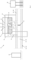
- a first embodiment of a cryogen cooling system according to the invention is shown in Figure 3 , generally indicated as 10, while an alternative embodiment of a cooling system according to the invention in shown in Figure 4 , generally indicated as 110.
- like components have been accorded like reference numerals and unless otherwise stated, perform a like function.
- cryogen cooling system 10; 110 of the invention utilises an elongate cryostat defining at least a part of a fluid flow path for the liquid cryogen.
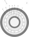
- FIG. 1 of the accompanying drawings there is illustrated a cross section of a first embodiment of such a cryostat, generally indicated as 50, which can thus form part of the cryogen cooling system 10; 110 of the present invention.
- the cryostat 50 may be part of a superconducting cable including superconducting material cooled by the liquid cryogen conveyed through the cryostat 50 alongside or surrounding the superconducting material.
- the cryogen is in thermal and optionally physical communication with the superconducting material in order to be capable of maintaining the temperature thereof at the requisite operating temperature, for example between 63 and 77 Kelvin in the case of a high temperature superconducting material.
- cryostat 50 defines an inner lumen 52 within an inner pipe 54 through which the cryogen is transported, preferably in the liquid phase, and in the case of a superconducting cable this inner lumen 52 may also contain the superconductor (not shown), surrounded by and in thermal communication with the liquid cryogen.
- the superconducting material may be located outside the inner lumen 52 or inner pipe 54 once it is in thermal communication with the cryogen contained therein.
- the cryostat 50 further comprises a dielectric barrier pipe 56 concentrically arranged radially outward of and spaced from the inner pipe 54 such as to define a thermally insulating vacuum annulus 58 surrounding the inner lumen 52.
- a further gas containment pipe 60 is arranged radially outward of and spaced from the dielectric barrier pipe 56 such as to define an optionally annular second lumen 62 in which, in use, a gaseous cryogen may be located or circulated in order to provide further thermal insulation for the inner lumen 52, absorbing significant radial heat ingress and thus enabling an extension of the distance that the liquid cryogen contained within the inner lumen 52 can be maintained at the necessary cryogenic temperature without or between being subcooled as detailed hereinafter.
- the cryostat 50 comprises an outer pipe 64 arranged radially outward of and spaced from the gas containment pipe 60 such as to define a further thermally insulating vacuum annulus 66.
- the outer pipe 63 may also comprise a dielectric material as an alternative or addition to the dielectric function of the barrier pipe 56.
- additional and/or alternative layers or layups or insulation, dielectric and other material may be employed as required to provide particular performance characteristics or to suit particular applications and/or environments.
- FIG. 2 there is illustrated a cross section of a second embodiment of a cryostat, generally indicated as 150, which can also form part of the cryogen cooling system 10; 110 of the present invention.
- the cryostat 150 may be part of a superconducting cable including superconducting material cooled by the liquid cryogen conveyed through the cryostat 150 alongside or surrounding the superconducting material.
- the cryostat 150 again defines an inner lumen 152 within an inner pipe 154 through which the liquid cryogen is transported, and in the case of a superconducting cable this inner lumen 152 may also contain the superconductor (not shown), surrounded by and in thermal communication with the cryogen.
- the cryostat 150 further defines an annular second lumen 162 in which, in use, a gaseous cryogen may be located or circulated in order to provide further thermal insulation for the inner lumen 152, absorbing significant radial heat ingress and thus allowing an extension of the distance that the cryogen contained in the inner lumen 152 can be maintained at the necessary cryogenic temperature.
- Extending longitudinally through the second lumen 162 are a circular array of longitudinally extending fluid tight tubes 168 in which the gaseous cryogen may be contained and pumped along the necessary length of the cryostat 150 in order to provide the necessary thermal sink to assist in maintaining the necessary temperature of the cryogen in the inner lumen 152.
- the second lumen 162 is radially offset from the inner pipe 152 such as to define a thermally insulting vacuum annulus 158 surrounding the inner pipe 154.
- the cryostat 150 comprises an outer pipe 164 arranged radially outward of and spaced from the second lumen 162 such as to define a further thermally insulating vacuum annulus 166. It will again be appreciated that any one or more of the above pipes or layers may comprise a dielectric material.
- cryostat 50; 150 which may comprise multiple discrete lengths of the cryostat 50; 150 joined end to end by means an appropriate joint 170.
- cryostat 50; 150 is shown schematically and not all the features thereof are illustrated.
- a cooling chamber 12 in the form of a pressure resistant vessel is provided, externally of the cryostat 50; 150, and through which at least a portion of the liquid cryogen from the inner lumen 52; 152 of the cryostat 50; 150 is diverted in order to cool the cryogen back down to the above mentioned operating temperature before being reintroduced into the cryostat 50; 150.
- a cryogen supply line 14 extends from the inner lumen 52; 152 into the cooling chamber 12 while a cryogen return line 16 extends from the cooling chamber 12 back to the cryostat 50; 150, effectively forming an extension of the fluid flow path defined by the inner lumen 52; 152 of the cryostat 50; 150.
- the supply line 14 and return line 16 may be provided as part of or on either side of the joint 170 connecting two lengths of the cryostat 50; 150 or may otherwise be arranged to divert the working cryogen from the inner lumen 52; 152 at appropriate locations along the length of the cryostat 50; 150.
- the supply line 14 may take cryogen at one joint (not shown) while the return line 16 may be feed cryogen back in at another joint on the cryostat 50; 150.
- a heat exchanger in the form of a cooling element 18 extends through the interior of the cooling chamber 12 between the supply line 14 and the return line 16 to form a portion of the cryogen fluid flow path.
- the cooling element 18 is a simple fluid tight tube which is optionally undulating or coiled in order to increase the length of the fluid flow path defined by the cooling element 18.
- the cryogen flow path from the supply line 14, through the cooling element 18 and through the return line 16 is in fluid isolation from the interior of the cooling chamber 12, but is in thermal communication therewith, for example by means of the material selected for at least the cooling element 18, namely a thermally conductive material.
- the interior of the cooling chamber 12 is at least partially filled with a cooling fluid 20, optionally the same cryogen flowing through the cryostat 50; 150, such that the cooling element 18 is at least partially and optionally completely immersed in the cooling fluid 20.
- the cooling element 18 of the fluid flow path thus effectively defines a heat exchanger operable to transfer heat from the cryogen flowing through the fluid flow path defined by the cooling element 18 into the cooling fluid 20.
- a fill line 22 may be provided from the supply line 14 to the cooling chamber 12 in order to fill and maintain the level of cooling fluid 20 in the cooling chamber 12. Suitable flow controls (not shown) such as valves or the like may be provided on the fill line 22 in order to manage the flow rate of cooling fluid into the cooling chamber 12.
- the cryostat 50; 150 is continuous between the supply line 14 and return line 16, particularly in the case of superconducting cable applications, with electrically conducting and preferably superconducting material (not shown) extending across the joint 170.
- this continuity is not a requirement and could be omitted given that the liquid cryogen can flow uninterrupted along the flow path defined by the supply line 14, cooling element 18 and return line 16.
- the joint 170 could form a fluid barrier within the inner lumen 52; 152.
- the cooling system 10 further comprises a venturi pump 24 having an inlet 26 and outlet 28 across which a fluid, preferably the same liquid cryogen as flows through the inner lumen 52; 152 and/or is contained in the cooling chamber 12, may be driven in order to create a reduced pressure region at a throat 30 of the venturi pump 24.
- the venturi pump 24 is located within a headspace of the cooling chamber 12 such that the reduced pressure region at the throat 30 effects a reduction of pressure within the headspace of the cooling chamber 12. It will also be understood that the venturi pump 24 could be located outside of the cooling chamber 12 with the throat 30 being arranged in fluid communication with the headspace of the cooling chamber 12 in order to achieve the same functionality.
- venturi pump 24 could be replaced with an alternative sub-cooler pump (not shown) such as a more conventional mechanically operated vacuum pump (not shown) as detailed in relation to an embodiment of the invention shown in Figure 6 .
- an alternative sub-cooler pump such as a more conventional mechanically operated vacuum pump (not shown) as detailed in relation to an embodiment of the invention shown in Figure 6 .
- the reduced pressure generated by the venturi pump 24 within the cooling chamber 12, for example 200mbar effects evaporative cooling of the bath of cooling fluid 20.
- the pressure established in the cooling chamber 12 may be carefully controlled, for example by the design and operation of the venturi pump 24, to ensure that the temperature of the cooling fluid 20 is maintained at the correct level to achieve the desired cooling of the cryogen flowing through the cooling element 18.
- the fill line 22 can be operated to maintain a set level of cooling fluid 20 within the cooling chamber 12.
- the fill line 22 is operated to extract approximately 10% of the cryogen from the cryostat 50; 150 in order to replace the evaporated cooling fluid 20.
- a venturi supply line 32 extends from a base of the cooling chamber 12 to the inlet 26 of the venturi pump 24 such that the cooling fluid 20 may be used as the source of driving fluid for the venturi pump 24.
- the venturi supply line 32 extends below the cooling chamber 12 before extending upwardly to the venturi pump 24.
- the distance the venturi supply line 32 extends below the cooling chamber 12 is selected to establish a hydraulic pressure head in the venturi supply line 32 which can then support the pressurised evaporation of the cooling fluid 20, for example liquid nitrogen, in the upwardly extending portion of the venturi supply line 32 to create a pressurised flow of gaseous nitrogen (or other cryogen) to be driven through the venturi pump 24.
- the pressure head can also act to prevent backflow of the cooling fluid 20 in the venturi supply line 32.
- a check valve (not shown) and/or expansion valve (not shown) may be provided in the venturi supply line 32, for example along the lowermost section thereof, to facilitate the phase change from liquid to gaseous cryogen.
- the thermal design of the venturi supply line 32 may be such as to effect controlled evaporation and pressurisation of the gaseous cryogen in order to drive the venturi pump 24. Further optionally heating elements (not shown) may be employed to effect vaporisation of the liquid cryogen in the venturi supply line 32. This flow of gaseous cryogen is then the driving fluid of the venturi pump 24 which can be utilised to reduce the pressure in the cooling chamber 12 by means suction generated at the throat 30 of the venturi pump 24 and thus within the headspace of the cooling chamber 12.
- the temperature of the cryogen returned to the cryostat 50; 150 through the return line 16 can be maintained at the necessary level by means of the cooling chamber 12 and venturi pump 24 which do not include any moving parts, thus greatly improving the reliability of the cryogen cooling process.
- the cryogen cooling system 10 employs a second cooling stage, utilising gaseous exhaust cryogen from the venturi pump 24 to supply and maintain a thermal sink envelope of gaseous cryogen in the second lumen 62; 162.
- the cryogen cooling system 10 thus comprises a venturi exhaust line 34 extending from the outlet 28 of the venturi pump 24 to the second lumen 62; 162 of the cryostat 50; 150 in order to facilitate the channelling of the gaseous cryogen, for example gaseous nitrogen, exiting the outlet 28 following expansion through the venturi pump 24, combined with the gaseous cryogen drawn out of the cooling chamber 12 via the throat 30.
- the venturi pump 24 is configured to generate sufficient pressure in the exhausted gaseous cryogen to drive the cryogen along the necessary length of the cryostat 50; 150, although it is also envisaged that additional downstream pressure management may be employed if required.
- venturi exhaust line 34 passes out of the cooling chamber 12 before extending downwardly into the cryostat 50; 150, opening into the second lumen 62; 162.
- the gaseous cryogen will flow directly into the second lumen 62 to surround the inner lumen 52 along a predetermined length of the cryostat.
- This envelope of gaseous cryogen thus provides sensible cooling along the respective length of the cryostat 50.
- the gaseous cryogen can also absorb significant radial heat ingress and serves to maintain a reduced temperature of the liquid cryogen (and superconductor) within the inner lumen 52, extending the distance necessary between adjacent cooling chambers 12 along the extended length of the superconducting cable.
- the gaseous cryogen is fed into the circular array of longitudinally extending tubes 168 which provide the same thermal management functionality.
- a suitable manifold (not shown) may be arranged to distribute the gaseous cryogen into the tubes 168.
- the gaseous cryogen may then be vented to the surroundings or may be captured for reuse.
- the liquid cryogen supplying the inner lumen 52, 152 may be supplied from an onshore cryogen supply station 36 while the vented gaseous cryogen from the second lumen 62; 162 may be captured for reuse at an offshore collection station 38.
- the cooling system 110 comprises the cryostat 50; 150 defining a fluid flow path for a liquid cryogen within the inner lumen 52; 152, a cooling chamber 112 into which extends a supply line 114 and out of which runs a return line 116, with a first heat exchanger in the form of a cooling element 118 connected therebetween within the interior space of the cooling chamber 112.
- the cooling element 118 is in the form of a coiled or corrugated tube of thermally conductive material, the cooling chamber 112 being filled with a cooling fluid 120 to immerse the cooling element 118.
- a fill line 122 is provided between the inner lumen 52; 152 and the cooling chamber 112 in order to allow the level of the cooling fluid 120 to be maintained despite evaporation during use, with the cryogen being replenished directly from the liquid cryogen flowing though the inner lumen 52; 152.
- a flow control valve 122a is provided on the fill line 122 to manage the supply of cryogen to the cooling chamber 112.
- the cryogen cooling system 110 further comprises a venturi pump 124 having an inlet 126 and outlet 128 across which a fluid, preferably the same liquid cryogen as flows through the inner lumen 52; 152 may be driven in order to create a reduced pressure region at a throat 130 of the venturi pump 124.
- the venturi pump 124 is located within a headspace of the cooling chamber 112 such that the reduced pressure region at the throat 130 effects a reduction of pressure within the headspace of the cooling chamber 112 as hereinbefore described. Again it will be understood that the venturi pump 124 could be located outside of the cooling chamber 112.
- the inlet 126 is connected via a venturi supply line 132 to the inner lumen 52; 152 such that the liquid cryogen from the cryostat 50; 150 is used directly as the source of driving fluid for the venturi pump 124.
- the liquid cryogen is then allowed to evaporate to create a pressurised flow of gaseous nitrogen (or other cryogen) to be driven through the venturi pump 124.
- An expansion valve 126a is provided in the venturi supply line 132 to facilitate this phase change from liquid to gaseous cryogen. This flow of gaseous cryogen is then the driving fluid of the venturi pump 124.
- the venturi pump 124 further comprises an outlet 128 extending from which is a venturi exhaust line 134 and which is connected at the opposed end into the second lumen 62; 162 of the cryostat 50; 150 to provide a second stage of cooling as hereinbefore described with reference to the previous embodiment.
- the venturi exhaust line 134 in this embodiment passes through a second heat exchanger 140 which is located within the cooling chamber 112, and preferably submerged within the liquid phase of the cryogen 120 contained therein.
- the heat exchanger 140 can lower the temperature of the gaseous cryogen prior to being introduced into the second lumen 62; 162 in order to increase the cooling efficiency of this second cooling stage. It will be appreciated that such a heat exchanger could be utilised with the cooling system 10 of the previous embodiment.
- the cooling element 18; 118 may be arranged to facilitate fluid transfer in the form of evaporation of a portion of the cryogen flowing from the inner lumen 52; 152 through the interior volume of the cooling chamber 12; 112 in order to effect cooling of the remaining liquid cryogen in the catheter 50; 150 via the latent heat of vaporisation.
- the interior volume of the cooling chamber 12; 112 would not filled with a cooling fluid in order to allow this evaporation to take place.
- the cooling element 18; 118 would then be provided in the form of a tube of porous or wick like material forming an outer wall of the cooling element and across which a portion of the liquid cryogen will migrate.
- the cooling element 18; 118 may be arranged to facilitate fluid transfer in the form of evaporation of a portion of the liquid cryogen flowing through the cooling element 18; 118 by incorporating a plurality of nozzles (not shown) which may be provided on or formed integrally with the cooling element 18; 118 when in tubular form as described above.
- the nozzles (not shown) are configured to effect evaporation of the cryogen in response to passage through the nozzles in combination with a low pressure environment within the cooling chamber 12; 112. This evaporation of a portion of the cryogen through the nozzles will effect cooling of the remaining liquid cryogen which then flows out of the cooling chamber 12; 112 and back into the inner lumen 52; 152 to continue cooling the superconducting material.
- Examples of such nozzles and a detailed explanation of the configuration and operation of exemplary configurations are disclose in the Applicant's International patent application PCT/EP2023/061767 .
- the cooling system 10; 110 of the present invention may comprise, as illustrated schematically in Figure 5 , a supply of liquid and/or gaseous cryogen 40 which may be in the form of a discrete reservoir or a continuous supply, and may for example be located in close proximity to one or both ends of the cryostat 50; 150.
- Intermediate cryogen supplies 40 may also be provided at various positions along the length of the cryostat 50; 150 if required, for example in the case of very long distance power transmission applications or the like.
- the cryogen supply 40 is preferably arranged to be capable of providing a supply of liquid cryogen to the inner lumen 52; 152, whether continuously or intermittently, and for example to maintain the correct operational levels of liquid cryogen therein, which will be consumed over time by the cooling chamber 12; 112; and/or the venturi pump 34; 134.
- a liquid feed line 42 thus extends from the cryogen supply 40 to the inner lumen 52; 152.
- cryogen supply 40 is preferably additionally or alternatively arranged to be capable of providing a supply of gaseous cryogen to the outer lumen 62; 162 in order to again establish and/or maintain the correct operational levels of cryogen therein.
- the cryogen supply 40 may be used to initially fill the outer lumen 62; 162 until the venturi pump 34; 134 is fully operational and supplying the necessary volume of gaseous cryogen from the exhaust thereof.
- a gaseous feed line 44 extends from an upper portion of the cryogen supply 40 to one or more entry points in the second lumen 62; 162.
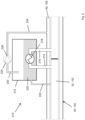
- the cooling system 210 comprises the cryostat 50; 150 defining a fluid flow path for a liquid cryogen within the inner lumen 52; 152, a cooling chamber 212 into which extends a supply line 214 and out of which runs a return line 216, with a first heat exchanger in the form of a cooling element 218 connected therebetween within the interior space of the cooling chamber 212.
- the cooling element 218 may be in the form of a coiled or corrugated tube of thermally conductive material, the cooling chamber 212 being filled with a cooling fluid 220 to immerse the cooling element 218.
- a fill line 222 is provided between the inner lumen 52; 152 and the cooling chamber 212 in order to allow the level of the cooling fluid 220 to be maintained despite evaporation during use, with the cryogen being replenished directly from the liquid cryogen flowing though the inner lumen 52; 152.
- the cryogen cooling system 210 further comprises a sub-cooler pump 224 located outside the cooling chamber 212 and which may for example be a conventional electrically powered and mechanically driven vacuum pump.
- the sub-cooler pump 224 is in fluid communication with a headspace of the cooling chamber 212 by means of an intake 230 in order to generate reduced pressure within the headspace as hereinbefore described. It will be understood that the sub-cooler pump 224 could be located within the cooling chamber 212.
- the sub-cooler pump 224 is thus operable to generate a pressurised flow of gaseous nitrogen (or other cryogen) drawn from the cooling chamber 212 which is driven through the sub-cooler pump 224 and exhausted at an outlet 228.
- Extending from the outlet 228 is an exhaust line 234 which is connected at the opposed end into the second lumen 62; 162 of the cryostat 50; 150 to provide a second stage of cooling as hereinbefore described with reference to the previous embodiments.
- the exhaust line 234 may, as in the previous embodiment, be passed through a second heat exchanger (not shown) located within the cooling chamber 212, and preferably submerged within the liquid phase of the cryogen 220 contained therein. In this way the heat exchanger can lower the temperature of the gaseous cryogen prior to being introduced into the second lumen 62; 162 in order to increase the cooling efficiency of this second cooling stage.
- thermoelectric devices such as a peltier cell may be employed to generate local electrical power based on a temperature differential which may be established using the reduced temperatures of the cryogenic fluids employed. This locally generated power may be used to operate one or more components of the cooling system 10; 110.
- cryogen cooling systems 10; 110 of the invention allow for localised cooling of the cryogen flowing through the cryostat 50; 150, and by means of a venturi pump 24; 124.
- the single venturi pump effects both cooling stages, the cooling of the liquid cryogen flowing through the inner lumen 52; 152 and the generation and/or cooling of the gaseous cryogen flowing through the second lumen 62; 162.
- conventional vacuum pumps can be avoided, which employ high speed drive shafts/rotors, seals, and other moving parts that can wear and thus reduce performance.
- any reduction in performance of such a crucial component which would lead to a reduction in the cooling performance and therefore an unacceptable increase in the temperature of the superconducting material, can lead to catastrophic failure.
Landscapes
- Engineering & Computer Science (AREA)
- Mechanical Engineering (AREA)
- General Engineering & Computer Science (AREA)
- Physics & Mathematics (AREA)
- Thermal Sciences (AREA)
- Chemical & Material Sciences (AREA)
- Combustion & Propulsion (AREA)
Priority Applications (2)
| Application Number | Priority Date | Filing Date | Title |
|---|---|---|---|
| EP23216741.1A EP4571792A1 (fr) | 2023-12-14 | 2023-12-14 | Système de refroidissement cryogénique à deux étages |
| US18/976,490 US20250198571A1 (en) | 2023-12-14 | 2024-12-11 | Two stage cryogen cooling system |
Applications Claiming Priority (1)
| Application Number | Priority Date | Filing Date | Title |
|---|---|---|---|
| EP23216741.1A EP4571792A1 (fr) | 2023-12-14 | 2023-12-14 | Système de refroidissement cryogénique à deux étages |
Publications (1)
| Publication Number | Publication Date |
|---|---|
| EP4571792A1 true EP4571792A1 (fr) | 2025-06-18 |
Family
ID=89223223
Family Applications (1)
| Application Number | Title | Priority Date | Filing Date |
|---|---|---|---|
| EP23216741.1A Pending EP4571792A1 (fr) | 2023-12-14 | 2023-12-14 | Système de refroidissement cryogénique à deux étages |
Country Status (2)
| Country | Link |
|---|---|
| US (1) | US20250198571A1 (fr) |
| EP (1) | EP4571792A1 (fr) |
Citations (3)
| Publication number | Priority date | Publication date | Assignee | Title |
|---|---|---|---|---|
| US20140051582A1 (en) * | 2012-08-14 | 2014-02-20 | Nexans | Arrangement with at least one superconductive cable |
| EP4199009A1 (fr) * | 2021-12-14 | 2023-06-21 | Supernode Limited | Système de câble supraconducteur avec refroidissement par évaporation |
| EP4273468A1 (fr) * | 2022-05-05 | 2023-11-08 | Supernode Limited | Système et procédé de refroidissement cryogénique |
-
2023
- 2023-12-14 EP EP23216741.1A patent/EP4571792A1/fr active Pending
-
2024
- 2024-12-11 US US18/976,490 patent/US20250198571A1/en active Pending
Patent Citations (3)
| Publication number | Priority date | Publication date | Assignee | Title |
|---|---|---|---|---|
| US20140051582A1 (en) * | 2012-08-14 | 2014-02-20 | Nexans | Arrangement with at least one superconductive cable |
| EP4199009A1 (fr) * | 2021-12-14 | 2023-06-21 | Supernode Limited | Système de câble supraconducteur avec refroidissement par évaporation |
| EP4273468A1 (fr) * | 2022-05-05 | 2023-11-08 | Supernode Limited | Système et procédé de refroidissement cryogénique |
Also Published As
| Publication number | Publication date |
|---|---|
| US20250198571A1 (en) | 2025-06-19 |
Similar Documents
| Publication | Publication Date | Title |
|---|---|---|
| CN101796597B (zh) | 冷却方法 | |
| CN100535503C (zh) | 使用热电能单元和以液态形式存储的天然气的能量系统 | |
| US20140150471A1 (en) | Method for cooling a plant for superconductive cables | |
| CN101137865B (zh) | 能量网络的管道部件及其应用和管道输送低温载能体的方法及对此适用的装置 | |
| US11540419B2 (en) | Systems and methods for cooling of superconducting power transmission lines | |
| US12488915B2 (en) | Apparatus for transmitting electrical energy with a superconducting current carrier | |
| WO2022077570A1 (fr) | Système de réfrigération à contre-courant à une seule extrémité pour câble supraconducteur | |
| US11362503B2 (en) | Method and device for cooling a superconducting current carrier | |
| US20250198571A1 (en) | Two stage cryogen cooling system | |
| EP4495511A1 (fr) | Système de refroidissement cryogénique | |
| WO2022077568A1 (fr) | Système de réfrigération aval à extrémité unique pour câble supraconducteur | |
| CN118640636A (zh) | 耦合氢气液化与超导电机液氢冷却的复合低温制冷系统 | |
| EP4273468A1 (fr) | Système et procédé de refroidissement cryogénique | |
| EP4703622A1 (fr) | Réservoir de stockage de liquide | |
| CN113790317B (zh) | 一种低温液体传输管线装置 | |
| US12613003B2 (en) | Hydrogen gas transfer system | |
| CN120636944A (zh) | 一种空间用超导电缆低温系统 | |
| Michel et al. | Preliminary studies of the MINERVA cryogenic supply system | |
| Ballarino et al. | Conceptual study of the cryostats for the cold powering system for the triplets of the High Luminosity LHC | |
| CN121655200A (zh) | 一种回热式深冷氦气循环制冷系统 | |
| CN119808639A (zh) | 高温超导电缆冷却系统的热力-水力耦合模型构建方法 | |
| Willems et al. | Closed loop cooling systems for HTS applications | |
| CN119234108A (zh) | 用于由低温液体蒸发产生的气体的储存和处理设施 | |
| CN121184741A (zh) | 一种液氢储存容器用高效安全气化器及液氢气化方法 | |
| CN118729144A (zh) | 介质存储容器 |
Legal Events
| Date | Code | Title | Description |
|---|---|---|---|
| PUAI | Public reference made under article 153(3) epc to a published international application that has entered the european phase |
Free format text: ORIGINAL CODE: 0009012 |
|
| STAA | Information on the status of an ep patent application or granted ep patent |
Free format text: STATUS: THE APPLICATION HAS BEEN PUBLISHED |
|
| AK | Designated contracting states |
Kind code of ref document: A1 Designated state(s): AL AT BE BG CH CY CZ DE DK EE ES FI FR GB GR HR HU IE IS IT LI LT LU LV MC ME MK MT NL NO PL PT RO RS SE SI SK SM TR |
|
| STAA | Information on the status of an ep patent application or granted ep patent |
Free format text: STATUS: REQUEST FOR EXAMINATION WAS MADE |
|
| 17P | Request for examination filed |
Effective date: 20251212 |