EP4571802A1 - Unité d'étranglement, éolienne et utilisation d'une unité d'étranglement comprenant une éolienne - Google Patents
Unité d'étranglement, éolienne et utilisation d'une unité d'étranglement comprenant une éolienne Download PDFInfo
- Publication number
- EP4571802A1 EP4571802A1 EP23215621.6A EP23215621A EP4571802A1 EP 4571802 A1 EP4571802 A1 EP 4571802A1 EP 23215621 A EP23215621 A EP 23215621A EP 4571802 A1 EP4571802 A1 EP 4571802A1
- Authority
- EP
- European Patent Office
- Prior art keywords
- unit
- fluid
- throttle unit
- fluid channel
- throttle
- Prior art date
- Legal status (The legal status is an assumption and is not a legal conclusion. Google has not performed a legal analysis and makes no representation as to the accuracy of the status listed.)
- Pending
Links
Images


Classifications
-
- H—ELECTRICITY
- H01—ELECTRIC ELEMENTS
- H01F—MAGNETS; INDUCTANCES; TRANSFORMERS; SELECTION OF MATERIALS FOR THEIR MAGNETIC PROPERTIES
- H01F37/00—Fixed inductances not covered by group H01F17/00
-
- H—ELECTRICITY
- H01—ELECTRIC ELEMENTS
- H01F—MAGNETS; INDUCTANCES; TRANSFORMERS; SELECTION OF MATERIALS FOR THEIR MAGNETIC PROPERTIES
- H01F27/00—Details of transformers or inductances, in general
- H01F27/08—Cooling; Ventilating
-
- H—ELECTRICITY
- H01—ELECTRIC ELEMENTS
- H01F—MAGNETS; INDUCTANCES; TRANSFORMERS; SELECTION OF MATERIALS FOR THEIR MAGNETIC PROPERTIES
- H01F27/00—Details of transformers or inductances, in general
- H01F27/08—Cooling; Ventilating
- H01F27/085—Cooling by ambient air
-
- H—ELECTRICITY
- H01—ELECTRIC ELEMENTS
- H01F—MAGNETS; INDUCTANCES; TRANSFORMERS; SELECTION OF MATERIALS FOR THEIR MAGNETIC PROPERTIES
- H01F27/00—Details of transformers or inductances, in general
- H01F27/08—Cooling; Ventilating
- H01F27/10—Liquid cooling
-
- H—ELECTRICITY
- H01—ELECTRIC ELEMENTS
- H01F—MAGNETS; INDUCTANCES; TRANSFORMERS; SELECTION OF MATERIALS FOR THEIR MAGNETIC PROPERTIES
- H01F3/00—Cores, Yokes, or armatures
- H01F3/10—Composite arrangements of magnetic circuits
- H01F3/14—Constrictions; Gaps, e.g. air-gaps
Definitions
- the invention relates to a throttle unit. Furthermore, the invention relates to a wind turbine. Finally, the invention relates to the use of a throttle unit with a wind turbine.
- a choke unit can also be simply referred to as a reactor.
- a choke unit is, for example, an electromagnetic three-phase choke coil.
- Such choke units are used, for example, to limit current particles in electrical lines, for intermediate energy storage, for impedance matching, and/or for filtering.
- such chokes can be used on the grid side at the output of an inverter to shape modulated current as sinusoidally as possible before it is fed into an electrical supply network.
- the choke is preferably arranged between the inverter and the electrical supply network into which the energy is to be fed.
- a corresponding choke and its arrangement are described, for example, in DE 10 2016 122 435 A1 revealed.
- Such chokes can be arranged, for example, on the generator side at the input of an inverter, between a generator and this inverter.
- the chokes are provided between the inverter and the power grid.
- a choke is typically used for each phase or a 3-phase choke is used.
- the three chokes of a three-phase system can be combined to form a three-phase choke.
- a magnetic core composed of stacked sheets can be provided, which roughly resembles the figure eight of a digital display. This creates three magnetically connected legs, each of which houses a winding of a phase. A magnetic field resulting from a current in a winding in the magnetic leg of this winding partially passes through the other two magnetic legs of the remaining two windings. This means that the magnetic fields of all three windings and thus all three phases overlap.
- Such chokes heat up during operation and reach critical temperatures. This can, in particular, minimize the choke's efficiency and service life.
- the invention is therefore based on the object of providing a throttle unit, a wind turbine, and a use of the throttle unit with a wind turbine that is improved over the known solution.
- the invention is based on the object of providing a throttle unit, a wind turbine, and a use of the throttle unit with a wind turbine that is technically less complex and more cost-effective to manufacture, yet still ensures reliable temperature control of the throttle unit.
- a choke unit of the type described in the introduction comprising at least one leg extending between a first end and a second end, wherein the at least one leg is encompassed by a coil, a first yoke coupled to the first end of the at least one leg, a first electromagnetic insulation unit arranged between the first end of the at least one leg and the first yoke, characterized in that the first electromagnetic insulation unit has or forms a fluid channel, wherein the fluid channel is designed to carry a temperature control fluid for temperature control of the throttle unit.
- the invention is based on the inventors' discovery that the electromagnetic insulation unit itself can have or form the fluid channel without the need to arrange tubes, heat pipes, or other separate fluid-conducting lines in the electromagnetic insulation unit between the yoke and the leg, which form the fluid channel.
- This has the advantage of reducing the number of parts comprising a throttle unit and thus a wind turbine, which minimizes the effort required both in manufacturing, particularly in work preparation, and in production planning.
- the invention is based on the inventors' finding that the requirements for the electromagnetic insulation unit are reduced to the extent that a short circuit no longer needs to be prevented via the comparatively short distance between the legs and the tubes or heat pipes. In particular, this makes it possible to focus more on the thermal conductivity of the electromagnetic insulation unit, thus enabling improved temperature control of the throttle unit.
- the throttle unit is particularly intended for use with wind turbines.
- the throttle unit is preferably designed as a three-, four-, or five-leg throttle unit.
- a three-leg throttle unit has three legs, a four-leg throttle unit has four legs, and a five-leg throttle unit has five legs.
- the throttle unit preferably has a plurality of legs, each of which is surrounded by a coil configured as a primary winding.
- the throttle unit may be preferred for the throttle unit to have five legs, with three legs each having a coil configured as a primary winding and two legs configured as return legs.
- the return legs preferably form the outer legs of the throttle unit.
- the throttle unit described herein is preferably a 3-phase throttle unit.
- the throttle unit has a second yoke which is coupled to the second end of the at least one leg.
- the throttle unit has a second electromagnetic insulation unit which is arranged between the second end of the at least one leg and the second yoke.
- the first electromagnetic insulation unit and/or the second electromagnetic insulation unit have a thermal conductivity coefficient of at least 0.001 W m ⁇ K , preferably at least 0.1 W m ⁇ K , and/or at 20°C a thermal conductivity coefficient of maximum 50 W m ⁇ K , preferably maximum 3 W m ⁇ K , has.
- the first electromagnetic insulation unit and/or the second electromagnetic insulation unit consists of a glass-fiber-reinforced plastic and/or silicone or comprises glass-fiber-reinforced plastic and/or silicone.
- These materials have a particularly suitable thermal conductivity for use in throttle units.
- a further advantage of these materials is that they are frequently used and therefore relatively readily available.
- the first electromagnetic insulation unit and/or the second electromagnetic insulation unit comprise thermally conductive additives, wherein the thermally conductive additives preferably comprise silicone and/or ceramic additives. These additives preferably increase the thermal conductivity.
- the first electromagnetic insulation unit forms the fluid channel as a fluid line or as a fluid pipe and/or the second electromagnetic insulation unit forms the fluid channel as a fluid line or as a fluid pipe.
- the first electromagnetic insulation unit and/or the second electromagnetic insulation unit form a fluid channel wall of the fluid channel, which at least partially spatially delimits the fluid channel, wherein vortex generators and/or static mixers are arranged in the fluid channel, in particular on the fluid channel wall, which increase the surface area for heat dissipation to the temperature control fluid during operation and/or cause a turbulent flow of the temperature control fluid in the fluid channel, and/or a profiled surface, in particular a groove-shaped surface, is formed on the fluid channel wall, which increases the surface area for heat dissipation to the temperature control fluid during operation and/or causes a turbulent flow of the temperature control fluid in the fluid channel.
- Vortex generators have the effect of increasing the turbulence in the flow near the wall area of the fluid channel and thus the heat transfer coefficient.
- Static mixers cause the flow to mix, so that "colder” tempering fluid flows from the interior of the fluid channel outwards to the wall of the fluid channel, and "warmer” tempering fluid, which has already flowed along the wall of the fluid channel, is directed inwards away from the wall of the fluid channel. This improves heat transfer.
- a profiled surface enlarges the surface area of the wall of the fluid channel, allowing the transferable heat to increase preferentially.
- the tempering fluid is guided for tempering in the fluid channel during operation of the throttle unit.
- the temperature control fluid (F) consists of water and/or glycol and/or oil and/or a gas and/or a gas mixture, in particular air, and/or Flutec PP9 and/or the temperature control fluid comprises water and/or glycol and/or oil and/or gas and/or a gas mixture, in particular air, and/or Flutec PP9.
- a water- and/or oil-based temperature control fluid has a higher heat transfer coefficient than gaseous temperature control fluids.
- the use of a liquid temperature control fluid is disadvantageous in the event of leaks compared to a gaseous temperature control fluid.
- the fluid channel has a circular and/or a polygonal, in particular a quadrangular, square, rectangular or trapezoidal, cross-section.
- the fluid channel is designed for a volume flow of at least 0.5 l/min and/or a maximum of 5 l/min.
- the object is achieved by a wind turbine of the type described above, comprising a throttle unit according to the first aspect or preferred embodiments of this throttle unit.
- the wind turbine preferably has two, three, or more throttle units.
- the wind turbine comprises an inverter, wherein the choke unit is coupled between the inverter and a grid output connection of the wind turbine, wherein the grid output connection of the wind turbine can be coupled to a supply grid.
- the wind turbine comprises at least two inverters.
- the object is achieved by using a throttle unit according to the first aspect or preferred embodiments of this throttle unit with a wind turbine.
- FIG. 1 shows a schematic representation of a wind turbine according to the invention.
- the wind turbine 100 has a tower 102 and a nacelle 104 on the tower 102.
- An aerodynamic rotor 106 with three rotor blades 108 and a spinner 110 is provided on the nacelle 104.
- the aerodynamic rotor 106 is set in rotation by the wind and thus also rotates an electrodynamic rotor or rotor of a generator, which is directly or indirectly coupled to the aerodynamic rotor 106.
- the electrical generator is arranged in the nacelle 104 and generates electrical energy.
- the pitch angles of the rotor blades 108 can be changed by pitch motors at the rotor blade roots 109 of the respective rotor blades 108.
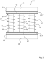
- the Figure 1 schematically illustrated exemplary embodiment of a wind turbine 100 comprises an inverter 200 and a choke unit 1, as shown in an exemplary embodiment in a first and second side view in the Figures 2 and 3 is shown schematically and is described below.
- the choke unit 1 is arranged between the inverter 200 and a grid output connection 300 of the wind turbine, wherein the grid output connection 300 is coupled to a supply grid.
- the schematically illustrated choke unit 1 has three legs 11, 12, 13, each extending between a first end E1 and a second end E2, wherein the three legs 11, 12, 13 are each encompassed by a coil L1, L2, L3.
- the three legs 11, 12, 13 are each coupled to a first yoke 21 at the first end E1 and to a second yoke 22 at the second end E2.
- the three legs 11, 12, 13 are magnetically decoupled from the first and second yokes 21, 22 by the first and second electromagnetic insulation units 31, 32.
- Both the first and the second electromagnetic isolation units 31, 32 have or form a fluid channel 40.
- the fluid channel 40 carries a temperature control fluid F for controlling the temperature of the throttle unit 1.
- the fluid channels 40 each have a rectangular cross-section. This is evident from the Figures 2 and 3 , in which the first and second electromagnetic insulation units 31, 32 are shown in section. In principle, however, the fluid channels 40 can also have a different polygonal cross-section or a circular cross-section. Regardless of the cross-section of the fluid channels, the temperature of the throttle unit 1 can be adjusted or regulated to a specific temperature or a specific temperature range using the temperature control fluid F. This temperature or this temperature range is selected such that the throttle unit 1 achieves the longest possible service life.
- the fluid channels are preferably designed with regard to their cross-section for a volume flow of at least 0.5 l/min and a maximum of 5 l/min.
- the first electromagnetic isolation unit 31 and the second electromagnetic isolation unit 32 form a fluid channel wall W of the fluid channel 40, which spatially delimits the fluid channel 40 orthogonally to the flow direction of the tempering fluid F.
- the fluid channel 40 of the first electromagnetic insulation unit 31 has vortex generators (not shown) and static mixers (not shown) on the fluid channel wall W. These, on the one hand, increase the surface area for heat dissipation to the temperature control fluid F and, on the other hand, cause a turbulent flow of the temperature control fluid F within the fluid channel, which improves heat dissipation from the throttle unit.
- the fluid channel wall W of the fluid channel 40 of the second electromagnetic insulation unit 32 has a groove-shaped surface (not shown), which increases the surface area for heat dissipation to the temperature control fluid F during operation and can also cause a turbulent flow of the temperature control fluid F in the fluid channel 40.
- the fluid channels of the first electromagnetic isolation unit 31 and the second electromagnetic isolation unit 32 are designed such that, during operation, the temperature control fluid F flows through the respective fluid channel 40 in order to set the desired temperature in the throttle unit 1.
- a temperature control fluid F consisting of or comprising water and/or glycol and/or oil and/or a gas and/or a gas mixture, in particular air, and/or Flutec PP9, for example, can be considered as the temperature control fluid F.
- the first electromagnetic insulation unit 31 and the second electromagnetic insulation unit 32 have a thermal conductivity coefficient of at least 0.001 W m ⁇ K and maximum 50 W m ⁇ K
- the electromagnetic insulation unit 31 and the second electromagnetic insulation unit 32 have a thermal conductivity coefficient at 20°C, preferably of at least 0.1 W m ⁇ K and a maximum of 3 W m ⁇ K have.
- the first electromagnetic insulation unit 31 and the second electromagnetic insulation unit 32 are made of a material having insulating properties.
- the first electromagnetic insulation unit 31 and the second electromagnetic insulation unit 32 may contain thermally conductive additives, wherein the thermally conductive additives preferably comprise silicone and/or ceramic additives.
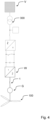
- FIG 4 shows a schematic circuit diagram of a network circuit of a wind turbine 100 according to a preferred embodiment with a Figures 2 and 3 illustrated throttle unit 1.
- the throttle unit 1 is arranged between a generator G of the wind turbine 100 and an inverter W. It is coupled to a supply grid V via a grid output connection 300 of the wind turbine 100.
Landscapes
- Engineering & Computer Science (AREA)
- Power Engineering (AREA)
- Chemical & Material Sciences (AREA)
- Composite Materials (AREA)
- Wind Motors (AREA)
Priority Applications (2)
| Application Number | Priority Date | Filing Date | Title |
|---|---|---|---|
| EP23215621.6A EP4571802A1 (fr) | 2023-12-11 | 2023-12-11 | Unité d'étranglement, éolienne et utilisation d'une unité d'étranglement comprenant une éolienne |
| PCT/EP2024/085388 WO2025125190A1 (fr) | 2023-12-11 | 2024-12-10 | Unité d'étranglement, éolienne et utilisation d'unité d'étranglement avec éolienne |
Applications Claiming Priority (1)
| Application Number | Priority Date | Filing Date | Title |
|---|---|---|---|
| EP23215621.6A EP4571802A1 (fr) | 2023-12-11 | 2023-12-11 | Unité d'étranglement, éolienne et utilisation d'une unité d'étranglement comprenant une éolienne |
Publications (1)
| Publication Number | Publication Date |
|---|---|
| EP4571802A1 true EP4571802A1 (fr) | 2025-06-18 |
Family
ID=89190845
Family Applications (1)
| Application Number | Title | Priority Date | Filing Date |
|---|---|---|---|
| EP23215621.6A Pending EP4571802A1 (fr) | 2023-12-11 | 2023-12-11 | Unité d'étranglement, éolienne et utilisation d'une unité d'étranglement comprenant une éolienne |
Country Status (2)
| Country | Link |
|---|---|
| EP (1) | EP4571802A1 (fr) |
| WO (1) | WO2025125190A1 (fr) |
Citations (2)
| Publication number | Priority date | Publication date | Assignee | Title |
|---|---|---|---|---|
| US20100308951A1 (en) * | 2007-10-24 | 2010-12-09 | Salomaeki Jarkko | Procedure for manufacturing a magnetic core and a magnetic core |
| DE102016122435A1 (de) | 2016-11-22 | 2018-05-24 | Wobben Properties Gmbh | Windenergieanlage und 3-Phasen-Drosseleinheit |
-
2023
- 2023-12-11 EP EP23215621.6A patent/EP4571802A1/fr active Pending
-
2024
- 2024-12-10 WO PCT/EP2024/085388 patent/WO2025125190A1/fr active Pending
Patent Citations (2)
| Publication number | Priority date | Publication date | Assignee | Title |
|---|---|---|---|---|
| US20100308951A1 (en) * | 2007-10-24 | 2010-12-09 | Salomaeki Jarkko | Procedure for manufacturing a magnetic core and a magnetic core |
| DE102016122435A1 (de) | 2016-11-22 | 2018-05-24 | Wobben Properties Gmbh | Windenergieanlage und 3-Phasen-Drosseleinheit |
Also Published As
| Publication number | Publication date |
|---|---|
| WO2025125190A1 (fr) | 2025-06-19 |
Similar Documents
| Publication | Publication Date | Title |
|---|---|---|
| DE112009005222B4 (de) | Transformator mit einem Wärmerohr und Verfahren zur Herstellung eines Transformators | |
| EP1481407A1 (fr) | Transformateur | |
| DE102021214491A1 (de) | Stator für eine elektrische Maschine und elektrische Maschine | |
| WO2015150556A9 (fr) | Conducteur creux électrique pour machine électromagnétique | |
| EP2319056A1 (fr) | Bobine de transformateur et transformateur a refroidissement passif | |
| DE102013204047A1 (de) | Spule und Verfahren zur Herstellung einer Spule | |
| WO2020057699A1 (fr) | Dissipateur thermique pour moteur électrique, moteur électrique et procédé de refroidissement du moteur | |
| EP4571802A1 (fr) | Unité d'étranglement, éolienne et utilisation d'une unité d'étranglement comprenant une éolienne | |
| DE102018206389A1 (de) | Dreiphasiger Transformator | |
| WO2018095852A1 (fr) | Éolienne et unité inductive à 3 phases | |
| DE102012103797A1 (de) | Flüssigkeitsgekühlter Widerstand | |
| DE112022000924T5 (de) | Spulengerät und Leistungskonvertierungsgerät | |
| EP3576256A1 (fr) | Conduite électrique à structure en grille et procédé de fabrication | |
| EP1906503A1 (fr) | Raccordement de générateur pour générateur d'une centrale électrique | |
| WO2018036805A1 (fr) | Dispositif de bobines | |
| WO2024115186A1 (fr) | Dispositif de refroidissement pour une machine électrique à convertisseur intégré | |
| EP3180839B1 (fr) | Générateur synchrone, en particulier générateur annulaire synchrone multipolaire d'une éolienne à entraînement direct, et éolienne munie de celui-ci | |
| DE1283343B (de) | Magnetohydrodynamischer (MHD-) Energiewandler | |
| EP3883099A1 (fr) | Unité de refroidissement pour une machine électrique et procédé de fabrication d'une unité de refroidissement | |
| EP4447269A1 (fr) | Agencement de bobine pour une machine électrique, stator, machine électrique et éolienne | |
| DE112020003830T5 (de) | Lufteinlassrahmen für einen rotor und generatorrotor | |
| DE102009026546A1 (de) | Sonnenkollektor | |
| WO2010049041A1 (fr) | Transformateur | |
| EP4303436B1 (fr) | Pale de rotor pour éoliennes et éolienne | |
| DE102020212463B4 (de) | Flüssigkeitsgekühlter Bremswiderstand mit Turbulator |
Legal Events
| Date | Code | Title | Description |
|---|---|---|---|
| PUAI | Public reference made under article 153(3) epc to a published international application that has entered the european phase |
Free format text: ORIGINAL CODE: 0009012 |
|
| STAA | Information on the status of an ep patent application or granted ep patent |
Free format text: STATUS: THE APPLICATION HAS BEEN PUBLISHED |
|
| AK | Designated contracting states |
Kind code of ref document: A1 Designated state(s): AL AT BE BG CH CY CZ DE DK EE ES FI FR GB GR HR HU IE IS IT LI LT LU LV MC ME MK MT NL NO PL PT RO RS SE SI SK SM TR |
|
| STAA | Information on the status of an ep patent application or granted ep patent |
Free format text: STATUS: REQUEST FOR EXAMINATION WAS MADE |
|
| 17P | Request for examination filed |
Effective date: 20251111 |