EP4571952A1 - Batteriezelle, vorrichtung zur herstellung einer batteriezelle und verfahren zum versiegeln von beutelfolien - Google Patents
Batteriezelle, vorrichtung zur herstellung einer batteriezelle und verfahren zum versiegeln von beutelfolien Download PDFInfo
- Publication number
- EP4571952A1 EP4571952A1 EP23217112.4A EP23217112A EP4571952A1 EP 4571952 A1 EP4571952 A1 EP 4571952A1 EP 23217112 A EP23217112 A EP 23217112A EP 4571952 A1 EP4571952 A1 EP 4571952A1
- Authority
- EP
- European Patent Office
- Prior art keywords
- dimension
- pouch
- foils
- foil
- battery cell
- Prior art date
- Legal status (The legal status is an assumption and is not a legal conclusion. Google has not performed a legal analysis and makes no representation as to the accuracy of the status listed.)
- Pending
Links
Images
Classifications
-
- H—ELECTRICITY
- H01—ELECTRIC ELEMENTS
- H01M—PROCESSES OR MEANS, e.g. BATTERIES, FOR THE DIRECT CONVERSION OF CHEMICAL ENERGY INTO ELECTRICAL ENERGY
- H01M50/00—Constructional details or processes of manufacture of the non-active parts of electrochemical cells other than fuel cells, e.g. hybrid cells
- H01M50/10—Primary casings; Jackets or wrappings
- H01M50/102—Primary casings; Jackets or wrappings characterised by their shape or physical structure
- H01M50/105—Pouches or flexible bags
-
- H—ELECTRICITY
- H01—ELECTRIC ELEMENTS
- H01M—PROCESSES OR MEANS, e.g. BATTERIES, FOR THE DIRECT CONVERSION OF CHEMICAL ENERGY INTO ELECTRICAL ENERGY
- H01M50/00—Constructional details or processes of manufacture of the non-active parts of electrochemical cells other than fuel cells, e.g. hybrid cells
- H01M50/10—Primary casings; Jackets or wrappings
- H01M50/102—Primary casings; Jackets or wrappings characterised by their shape or physical structure
- H01M50/112—Monobloc comprising multiple compartments
-
- H—ELECTRICITY
- H01—ELECTRIC ELEMENTS
- H01M—PROCESSES OR MEANS, e.g. BATTERIES, FOR THE DIRECT CONVERSION OF CHEMICAL ENERGY INTO ELECTRICAL ENERGY
- H01M50/00—Constructional details or processes of manufacture of the non-active parts of electrochemical cells other than fuel cells, e.g. hybrid cells
- H01M50/10—Primary casings; Jackets or wrappings
- H01M50/147—Lids or covers
- H01M50/148—Lids or covers characterised by their shape
-
- H—ELECTRICITY
- H01—ELECTRIC ELEMENTS
- H01M—PROCESSES OR MEANS, e.g. BATTERIES, FOR THE DIRECT CONVERSION OF CHEMICAL ENERGY INTO ELECTRICAL ENERGY
- H01M50/00—Constructional details or processes of manufacture of the non-active parts of electrochemical cells other than fuel cells, e.g. hybrid cells
- H01M50/10—Primary casings; Jackets or wrappings
- H01M50/172—Arrangements of electric connectors penetrating the casing
- H01M50/174—Arrangements of electric connectors penetrating the casing adapted for the shape of the cells
- H01M50/178—Arrangements of electric connectors penetrating the casing adapted for the shape of the cells for pouch or flexible bag cells
-
- H—ELECTRICITY
- H01—ELECTRIC ELEMENTS
- H01M—PROCESSES OR MEANS, e.g. BATTERIES, FOR THE DIRECT CONVERSION OF CHEMICAL ENERGY INTO ELECTRICAL ENERGY
- H01M50/00—Constructional details or processes of manufacture of the non-active parts of electrochemical cells other than fuel cells, e.g. hybrid cells
- H01M50/50—Current conducting connections for cells or batteries
- H01M50/543—Terminals
- H01M50/552—Terminals characterised by their shape
- H01M50/553—Terminals adapted for prismatic, pouch or rectangular cells
-
- Y—GENERAL TAGGING OF NEW TECHNOLOGICAL DEVELOPMENTS; GENERAL TAGGING OF CROSS-SECTIONAL TECHNOLOGIES SPANNING OVER SEVERAL SECTIONS OF THE IPC; TECHNICAL SUBJECTS COVERED BY FORMER USPC CROSS-REFERENCE ART COLLECTIONS [XRACs] AND DIGESTS
- Y02—TECHNOLOGIES OR APPLICATIONS FOR MITIGATION OR ADAPTATION AGAINST CLIMATE CHANGE
- Y02E—REDUCTION OF GREENHOUSE GAS [GHG] EMISSIONS, RELATED TO ENERGY GENERATION, TRANSMISSION OR DISTRIBUTION
- Y02E60/00—Enabling technologies; Technologies with a potential or indirect contribution to GHG emissions mitigation
- Y02E60/10—Energy storage using batteries
Definitions
- This disclosure is related to battery cells with multiple cavities, devices for manufacturing battery cells with multiple cavities, and methods for sealing pouch foils for batteries with multiple cavities.
- Electric pouch cells are a type of battery technology, e.g. for lithium-ion batteries, characterized by their packaging and construction structures. Unlike cylindrical or prismatic cells, pouch cells are housed in flexible, aluminum-coated, laminated foil pouches. This design can significantly reduce weight and allow for more versatile shapes and sizes, optimizing space utilization in various applications. The pouch format also offers improved thermal management due to the larger surface area and less rigid containment, which can be critical when water consumption is high. Internally, pouch cells consist of layers of electrodes and separators that are stacked or folded inside the pouch to form a stack of electrodes or a jelly roll. Further improvements, particularly with respect of weight and performance characteristics, are desirable.
- An object of the present disclosure is to improve a battery cell.
- a first aspect of the present disclosure is related to a battery cell, comprising:
- a cavity for an electrode stack can refer to a space or compartment within the battery cell, where the electrode stack is placed.
- An electrode stack usually consists of multiple electrodes (anodes and cathodes) and separators layered together.
- An electrode stack can also consist of a wound-up assembly of a cathode layer, a separator layer, and an anode layer (jelly roll).
- a cavity can be designed to accommodate the electrode stack in a sealed way such that no electrolyte can exit the cavity.
- a cavity can precisely fit the dimensions of the electrode stack, ensuring that the electrodes and separators are tightly packed without unnecessary space, which could affect the battery's performance.
- the cavities of a battery cell may be of the same size forming compartments for same-size electrode stacks.
- One or more sides, in particular a whole frame, of a cavity in a multi-cavity battery cell may be formed by pouch foils. Additionally also a top and/or a bottom of the cavity can be formed by pouch foil. This is explained in the remainder.
- a dimension refers to a virtual first straight line.
- a two-dimensional system comprises a first dimension and a second dimension.
- a three-dimensional system comprises an additional third dimension.
- a dimension can refer to a dimension or axis in a Cartesian coordinate system of perpendicular dimensions.
- a pouch foil for electrical batteries is a packaging material that encloses the battery's internal components, including the electrodes and electrolyte.
- the primary functions of this foil include providing a protective barrier, ensuring structural integrity, and maintaining an internal environment of the battery.
- a pouch foil can comprise aluminum.
- Aluminum can be a primary material of pouch foils. Aluminum seals against moisture and oxygen. Furthermore, it is also lightweight, conductive, and has good thermal properties. Additionally aluminum based pouch foil can be formed by deep drawing.
- An aluminum pouch foil can be laminated with polymers to enhance its properties. Such polymers can be, e.g. polyethylene, polypropylene, and/or polyethylene terephthalate. Polymer can add mechanical strength, thermal stability, and flexibility to a pouch foil.
- a construction of the pouch foil can be performed in a layered structure. The thickness of the foil is typically kept as minimal as possible to reduce weight and bulk, but sufficient enough to ensure the integrity and safety of the battery.
- a multi-cavity battery By forming a battery cell with a plurality of cavities and providing a pouch foil that separates both cavities, i.e. that forms a common side of both cavities, a multi-cavity battery can be obtained that can be used for a redundant energy source which can in particular provide large voltages at a relatively low weight.
- An embodiment of the first aspect is related to a battery cell, wherein a plurality of electrode stacks are connected in a serial connection.
- the battery cell By connecting the plurality of the electrode stacks in the battery in a serial connection, the battery cell can provide a compounded voltage capacity. This can in particular be useful for applications in which a large voltage needs to be provided and a low weight of the battery cell is desired.
- the electrode stacks of the different cavities can also be connected in a parallel connection. This can provide an increased current resource.
- the pouch-foils of the different cavities can be interconnected to each other, thereby forming a single, low resistance pole of the battery when connected to the same current collector type of the different electrodes.
- the other battery pole can be provided by an internal connection of the remaining current collector type of the different electrodes.
- An embodiment of the first aspect is related to a battery cell, comprising two second-dimension pouch foils that form opposite sides of the at least two cavities.
- a second-dimension can be a dimension perpendicular to the first dimension in which the other pouch foil is arranged. More general, a second dimension can be a dimension that defines another direction as the first dimension. Therefore, the second-dimension pouch foils can be arranged perpendicular to the first-dimension pouch foil. Alternatively, the second dimension-pouch foils can be arranged in another direction than the first dimension. Based on two-second dimension pouch foils that are arranged parallel to each other and which are attached to the first-dimension pouch foil, a rectangular cavity can be provided that is made by pouch foil on three adjacent sides.
- a second-dimension pouch foil can have a pre-defined extension in a second dimension and a pre-defined extension in a third dimension.
- Sealing one pouch foil to another pouch foil within the meaning of this disclosure relates to joining or attaching one film to another, in particular in such a way that no liquids can penetrate through the sealed area.
- Sealing can comprise different techniques, e.g. sealing with heat and pressure, by ultrasonic vibrations, electromagnetic waves, with one or more adhesives, by welding (laser welding) or by solvent or solventless lamination.
- An embodiment of the first aspect is related to a battery cell, wherein the first-dimension pouch foil is sealed on a first ending to one of the two second-dimension pouch foils and on a second ending to the second of the two second-dimension pouch foils.
- An embodiment of the first aspect is related to a battery cell, wherein a second first-dimension pouch foil is sealed to the two second-dimension pouch foils on the opposite cavity side relative to the first first-dimension pouch foil, thereby forming a closed circumference for one cavity.
- a closed circumference, i.e. frame, of pouch foils can be made for a cavity. This can be done without the necessity for a deep drawing operation as with conventional pouch cells, in particular if the four angles between the two first-dimension pouch foils and two the second-dimension pouch foils reach 360°.
- an additional cavity can be formed between the second dimension pouch foils. Therefore, only one additional first-dimension pouch-foil has to be arranged between the two second-dimension pouch foils.
- M -1 cavities can be formed along the second dimension. These cavities can have the same size, by spacing the first dimension pouch foils equally. This would provide a plurality of pouch foils along the second dimension.
- An embodiment of the first aspect is related to a battery cell, wherein a plurality of cavities is separated by the second-dimension pouch foils.
- the second-dimension pouch foils can have cavities arranged on both sides. Based on this feature and the fact that the second dimension pouch foils can form a side of a plurality of cavities, a battery cell with a two-dimensional matrix of cavities (i.e. electrode stacks) can be formed. The cavities can then have a tetragonal form. If the cavities have two-dimensional pouch foils on each of their side, N two-dimensional pouch foils can form sides of N - 1 cavities along the first dimension.
- a matrix of M first-dimension pouch foils and N second dimension can comprise N - 1 times M - 1 cavities.
- An embodiment of the first aspect is related to a battery cell, comprising a housing made of pouch foil.
- a housing relates to the outer shell of the battery.
- all inner sides of the cavities and the housing, i.e. the sides (the frame), the top, and the bottom, of the battery cell can be made of pouch foil.
- the resulting battery cell is then a multi-cavity pouch cell, i.e. a battery cell with structures made only of pouch foil.
- An embodiment of the first aspect is related to a battery cell, comprising a sealing hat placed on top of the electrode stack and sealed with the first-dimension pouch foil and/or with the second-dimension pouch foil.
- a housing may consist of first-dimension and second-dimension pouch foils to form the sides of the battery cell. Additionally, the top and/or the bottom can also be made of pouch foil. Therefore, the cavity structures may be sealed with a pre-formed means (so-called "sealing hat") that is configured to cover the top of a cavity.
- a sealing hat may be formed such that the bottom of the hat forms the top side of a cavity, when sealed to the cavity. Therefore, the bottom of the head can be formed as the top of the cavity, i.e. the hat bottom has a form defined by the cavity sides, e.g. the first-dimension and the second-dimension pouch foils.
- the sides of a hat can be used for sealing the sealing hat to the cavity. They can be, e.g. 4 to 8 mm high.
- the cavities are fully formed by first-dimension and second-dimension pouch foils, these pouch foils have a width (third dimension) that is larger than the length of an electrode stack arranged in the cavity.
- the sealing hat can be placed on the top of the electrode stack.
- the sides of the sealing hat can then be sealed to the parts of the first-dimension and/or second-dimension pouch foils that extend the electrode stack in their third dimension.
- a sealing hat may also be used in a corresponding way to seal the bottom of a cavity.
- the tabs can either be formed through the sealing hat, e.g. by a sealed incision. Additionally or alternatively, one tap can be connected to the sealing hat, i.e. to the housing of the battery, while another is formed as an isolated pole of the battery.
- An embodiment of the first aspect is related to a battery cell, comprising a sealing hat placed on the bottom of the electrode stack and sealed with the first-dimension pouch foil and/or the second-dimension pouch foil.
- the cavities of a multi-cavity pouch cell are sealed on the top by a sealing hat and on the bottom by a sealing hat. And both sealing hats are welded to the parts of the first-dimension and second dimension pouch foils that extend beyond an electrode stack (in the third dimension) arranged in the cavity.
- An embodiment of the first aspect is related to a battery cell, wherein a cathode tab and/or an anode tab extend the cavity on a bottom and/or on a top of the cavity.
- a tab related to one electrode type (cathode or anode), or tabs related to both electrode types (cathode and anode) can exit the cavity. Deepening on the application the tabs can be connected in different ways to provide the energy of the battery.
- An embodiment of the first aspect is related to a battery cell, wherein adjacent cavities comprise tabs of different electrode types on a side not covered by first-dimension and/or second-dimension pouch foils.
- This architecture can be used for a serial connection of electrode stacks in order to increase the voltage of the battery cell.
- a second aspect of the present disclosure is related to a device for manufacturing a multi-cavity battery cell, comprising:
- the seal bars are configured to seal an essentially rectangular connection between two pouch foils for a cavity of a battery cell.
- the device comprises only two seal bars, a two pouch foils, a first-dimension pouch foil and a second-dimension pouch foil can be sealed together. Therefore, at least one of the seal bars needs to be movable, such that the two pouch foils can be arranged in the device and then the seal bars move together and seal the two pouch foils together.
- the device can also comprise three seal bars, wherein one seal bar is even, and the other two seal bars are formed rectangular.
- a second-dimension pouch foil can then be arranged on the even seal bar and a first-dimension pouch foil can be arranged on the first rectangular seal bar.
- the part of the first-dimension pouch foil that is to be sealed can be pressed to the second-dimension pouch foil by the second rectangular seal bar.
- the second rectangular seal bar can then be configured as a movable seal bar.
- pouch-based batteries with a single cavity / electrode stack and with a plurality of cavities can be formed.
- An embodiment of the second aspect is related to a device for manufacturing a multi-cavity battery cell, comprising:
- the three movable seal bars are actuated, e.g. by one or more servo motors. Since the pouch foils are arranged between the seal bars, the seal bars only move towards a common point but do not touch each other.
- An embodiment of the second aspect is related to a device for manufacturing a multi-cavity battery cell, wherein the corners of one or more of the seal bars are round.
- An embodiment of the second aspect is related to a device for manufacturing a multi-cavity battery cell, wherein the corners are formed such that they can comprise a seal rod.
- sealing material such as a polymer
- a third aspect of the present disclosure is related to a method for sealing pouch-foils, in particular for batteries with multiple cavities, configured to:
- an electrolyte can be added using an injection needle, for example.
- Each electrode stack must be provided with an electrolyte, i.e. each cavity must be supplied with electrolyte.
- the holes created by the electrolyte injection needle can be sealed after the electrolyte filling operation is completed.
- the electrolyte can be provided from a side that comprises no taps. For example, in case the cavities are sealed on a top and on a bottom by sealing hats, the taps can be formed through the sealing hat that is arranged on the top side. The electrolyte can then be provided from the bottom side. After the electrolyte is provided, the bottom side can be sealed with a sealing hat for the bottom side.
- a disclosure of a described method also applies to a corresponding device (or apparatus) for carrying out the method or a corresponding system comprising one or more devices and vice versa.
- a corresponding device may include a feature to perform the described method step, even if that feature is not explicitly described or represented in the figure.
- a corresponding method may include one or more steps to perform the described functionality, even if such steps are not explicitly described or represented in the figures.
- a system can be provided with corresponding device features or with features to perform a particular method step.
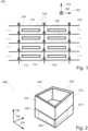
- Fig. 1 illustrates a multi-cavity pouch cell 100 according to an embodiment of this disclosure.
- frames for cavities of the cell are made of pouch foils.
- the battery cell is illustrated in a first dimension 102 and in a second dimension 104 of a Cartesian coordinate system and is shown from above 106.
- the battery cell 100 comprises first-dimension pouch foils 110 (arranged horizontally) which are sealed on both sides to second-dimension pouch foils 120 (arranged vertically).
- the first-dimension pouch foils have a vertical sealing portion 112 at each side.
- Two first-dimension pouch foils arranged vertically adjacent and two second-dimension pouch foils 120 on each side of the two first dimension pouch foils form a cavity 130.
- an electrode stack is arranged in the cavities 130.
- a tab of each electrode stack 132 leads out to the top side of the cavity.
- a plurality of cavities 130 can be arranged on a plane next to each other.
- the cavities can be connected in serial connection or in parallel connection.
- Fig. 2 illustrates an application of a sealing hat for sealing a top and/or a bottom of a cavity of a multi-cavity pouch cell, according to an embodiment of this disclosure.
- the battery cell is illustrated in a first dimension 102 and in a second dimension 104 of a Cartesian coordinate system and is shown from above 106. Only one cavity is depicted in the figure.
- First-dimension pouch foils 210 and second-dimension pouch foils 220 are sealed together to form a cavity.
- the cavity comprises an electrode stack 240.
- the first-dimension pouch foils and the second-dimension pouch foils form the sides, i.e. a frame, of the cavity.
- the top of the cavity is sealed with a sealing hat 230.
- the sealing hat is arranged in the space that is formed by the parts 212, 222 of the pouch foils 210, 220 that extend the electrode stack.
- the sealing hat is arranged on top of the electrode stack 240 such that the bottom 232 of the sealing hat 230 is supported by the top of the electrode stack 240.
- the sides of the sealing hat are then sealed to the extending sides 212, 222 of the pouch foils 210, 220.
- the sealing hat can also be made of pouch foil or any other material that has good sealing characteristics.
- One or both tabs can exit the cavity through the sealing hat 230. Therefore, an incision can be made in the sealing hat through which one tab of one electrode is led out of the cavity. If tabs of both electrodes are led out on the same side (e.g. through the same sealing hat) an isolation may be applied, for example, one or both tabs can be coated with an isolating material. Alternatively, the tabs can be led out of the cell by separate openings. This can in particular be implemented if the used pouch foil is isolating.
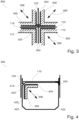
- Fig. 3 illustrates a sealing tool 300 for sealing two pouch foils according to an embodiment of this disclosure.
- the sealing tool comprises four sealing bars 302. Each sealing bar can be heated on a heating area 304. When the heating area touches two pouch foils arranged over each other, the foils are sealed together.
- the heating tool 300 is configured to heat at least from two sides. In. this way two or more layered pouch foils can be heated. As shown in the figure, two first-dimension pouch foils 110 are arranged horizontally with their sealing portion 112 arranged vertically and parallel to a second-dimension pouch foil 120. When the three actuated seal bars 302 move in their specified directions 306, the pouch foil 110 are sealed to the pouch foil 120 from both sides. This is a basic structure for a multi-cavity pouch cell that has sides made of different pouch foils sealed together.
- Fig. 4 illustrates a sealing tool 400 according to an embodiment of this disclosure.
- the sealing tool is illustrated by one seal bar, a lower right seal bar.
- the sealing tool can have the same design as the sealing tool of Fig. 3 . It has a heating area 404 and is movable along at least one direction 306.
- the corner of the seal bar 402 is formed round. This is done to avoid damages to the pouch foils during the sealing operation.
- a first-dimension pouch foil 110 is sealed to a second-dimension pouch foil 120 and to a sealing hat 430.
- a seal rod 410 is arranged in the space between the pouch foils 110, 120 and the flattened corners of the sealing hat 432 and of the seal bar 402.
- the seal rod 410 provides material that is used for the sealing and will be used during the sealing process. This provides an enforced sealing.
- a completed sealing operation of the same kind is depicted on the other side of the first-dimension pouch foil 110. It shows a sealed volume 430 connecting the pouch foils 110, 120, and the sealing hat 420.
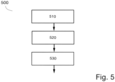
- Fig. 5 illustrates a basic procedure for sealing pouch foils in an angular manner, according to an embodiment of this disclosure.
- a first step 510 two pouch foils are placed under a plurality of seal bars.
- the seal bars are configured to seal the pouch foils in an angular manner, e.g. perpendicular towards each other.
- the seal bars can also consist of a single seal bar that is configured to press the pouch foils against a plate.
- one seal bar is configured movable, e.g. by a servo motor, in at least one dimension.
- the seal bars are moved together, to form the seal bars such that they are arranged in the desired angle and that they touch in one or more pre-defined sealing areas.
- a third step 530 the pouch foils which are arranged according to the desired angle within the seal bars are heated by the seal bars such that the pouch foils are sealed together.
- the seal bars can be formed such that between the seal bars and in the seal area a sealing rod can be placed.
- the sealing rod provides sealing material, e.g. a polymer or a metal, that will be consumed during the sealing process to enforce the sealing connection.
- a plurality of pouch foils can be sealed together, e.g. in a rectangular structure, based on the described basic procedure. This can yield a frame for a multi-cavity pouch cell, as depicted in Fig. 1 .
- an electrode stack can be placed in each cavity of this structure.
- the bottom and the top can be sealed by sealing hats, which can also consist or comprise pouch foil.
- An electrolyte can be provided to the electrode stack either before closing the top or the bottom of a cavity, or afterwards by injection.
- aspects have been described in the context of an apparatus, it is clear that these aspects also represent a description of the corresponding method, where a block or device corresponds to a method step or a feature of a method step. Analogously, aspects described in the context of a method step also represent a description of a corresponding block or item or feature of a corresponding apparatus.
Landscapes
- Chemical & Material Sciences (AREA)
- Chemical Kinetics & Catalysis (AREA)
- Electrochemistry (AREA)
- General Chemical & Material Sciences (AREA)
- Sealing Battery Cases Or Jackets (AREA)
Priority Applications (1)
| Application Number | Priority Date | Filing Date | Title |
|---|---|---|---|
| EP23217112.4A EP4571952A1 (de) | 2023-12-15 | 2023-12-15 | Batteriezelle, vorrichtung zur herstellung einer batteriezelle und verfahren zum versiegeln von beutelfolien |
Applications Claiming Priority (1)
| Application Number | Priority Date | Filing Date | Title |
|---|---|---|---|
| EP23217112.4A EP4571952A1 (de) | 2023-12-15 | 2023-12-15 | Batteriezelle, vorrichtung zur herstellung einer batteriezelle und verfahren zum versiegeln von beutelfolien |
Publications (1)
| Publication Number | Publication Date |
|---|---|
| EP4571952A1 true EP4571952A1 (de) | 2025-06-18 |
Family
ID=89222896
Family Applications (1)
| Application Number | Title | Priority Date | Filing Date |
|---|---|---|---|
| EP23217112.4A Pending EP4571952A1 (de) | 2023-12-15 | 2023-12-15 | Batteriezelle, vorrichtung zur herstellung einer batteriezelle und verfahren zum versiegeln von beutelfolien |
Country Status (1)
| Country | Link |
|---|---|
| EP (1) | EP4571952A1 (de) |
Citations (3)
| Publication number | Priority date | Publication date | Assignee | Title |
|---|---|---|---|---|
| US20110027508A1 (en) * | 2009-07-29 | 2011-02-03 | Mileti Robert J | Multi-Layer Product With Sealing Areas Of Varying Sealing Affinities |
| US20170025646A1 (en) * | 2015-06-18 | 2017-01-26 | Naoki Ota | Single pouch battery cells and methods of manufacture |
| US20230041540A1 (en) * | 2020-04-24 | 2023-02-09 | Byd Company Limited | Battery pack and electric vehicle |
-
2023
- 2023-12-15 EP EP23217112.4A patent/EP4571952A1/de active Pending
Patent Citations (3)
| Publication number | Priority date | Publication date | Assignee | Title |
|---|---|---|---|---|
| US20110027508A1 (en) * | 2009-07-29 | 2011-02-03 | Mileti Robert J | Multi-Layer Product With Sealing Areas Of Varying Sealing Affinities |
| US20170025646A1 (en) * | 2015-06-18 | 2017-01-26 | Naoki Ota | Single pouch battery cells and methods of manufacture |
| US20230041540A1 (en) * | 2020-04-24 | 2023-02-09 | Byd Company Limited | Battery pack and electric vehicle |
Similar Documents
| Publication | Publication Date | Title |
|---|---|---|
| EP2750241B1 (de) | Elektrodenanordnung mit gestuften ebenen und batteriezelle, batteriepackung und vorrichtung damit | |
| JP6290936B2 (ja) | バイポーラ電池とその作製方法並びに自動車 | |
| EP3579305B1 (de) | Elektrode mit verbesserter elektrodenlaschenschweisscharakteristik und sekundärbatterie damit | |
| JP6713547B2 (ja) | マルチキャビティのバッテリモジュール | |
| KR102488346B1 (ko) | 조전지 | |
| KR102927755B1 (ko) | 전고체전지 및 전고체전지의 제조방법 | |
| US10903500B2 (en) | Battery and cell stack | |
| US20050130037A1 (en) | Secondary battery having third terminal other than positive and negative electrode terminals and battery comprising it | |
| KR20200114784A (ko) | 이차 전지용 전지 케이스 및 파우치 형 이차 전지 | |
| CA2898816A1 (en) | Stacked-type secondary battery | |
| JP7488695B2 (ja) | 固体電池モジュール及び固体電池セル | |
| JP5451315B2 (ja) | 組電池 | |
| CN111937212A (zh) | 电池单体 | |
| KR20130097881A (ko) | 이차전지의 제조방법 및 이를 이용하여 생산되는 이차전지 | |
| JP5206711B2 (ja) | 蓄電モジュールと該モジュール用枠体 | |
| JP7538626B2 (ja) | 電池セル及び電池モジュール | |
| US20120050946A1 (en) | Supercapacitor module | |
| KR20220002540A (ko) | 셀 배터리 | |
| EP4571952A1 (de) | Batteriezelle, vorrichtung zur herstellung einer batteriezelle und verfahren zum versiegeln von beutelfolien | |
| KR20080019313A (ko) | 밀봉성이 우수한 파우치형 이차전지의 제조방법 | |
| KR101368236B1 (ko) | 플라스틱백을 구비하는 이차전지 및 그의 제조방법 | |
| JP2020170667A (ja) | 積層型電池の製造方法および積層型電池 | |
| JP7683617B2 (ja) | 電池および電池の製造方法 | |
| EP4383447A2 (de) | Verfahren zur herstellung einer batterie und batterie | |
| EP4657614A1 (de) | Batterie, batterieherstellungsverfahren und automatisierte anlage |
Legal Events
| Date | Code | Title | Description |
|---|---|---|---|
| PUAI | Public reference made under article 153(3) epc to a published international application that has entered the european phase |
Free format text: ORIGINAL CODE: 0009012 |
|
| STAA | Information on the status of an ep patent application or granted ep patent |
Free format text: STATUS: THE APPLICATION HAS BEEN PUBLISHED |
|
| AK | Designated contracting states |
Kind code of ref document: A1 Designated state(s): AL AT BE BG CH CY CZ DE DK EE ES FI FR GB GR HR HU IE IS IT LI LT LU LV MC ME MK MT NL NO PL PT RO RS SE SI SK SM TR |
|
| STAA | Information on the status of an ep patent application or granted ep patent |
Free format text: STATUS: THE APPLICATION IS DEEMED TO BE WITHDRAWN |