EP4572011A1 - Antenne und kommunikationsvorrichtung - Google Patents
Antenne und kommunikationsvorrichtung Download PDFInfo
- Publication number
- EP4572011A1 EP4572011A1 EP22957676.4A EP22957676A EP4572011A1 EP 4572011 A1 EP4572011 A1 EP 4572011A1 EP 22957676 A EP22957676 A EP 22957676A EP 4572011 A1 EP4572011 A1 EP 4572011A1
- Authority
- EP
- European Patent Office
- Prior art keywords
- resonator
- antenna
- reflector
- radiator
- phase adjustment
- Prior art date
- Legal status (The legal status is an assumption and is not a legal conclusion. Google has not performed a legal analysis and makes no representation as to the accuracy of the status listed.)
- Pending
Links
Images





Classifications
-
- H—ELECTRICITY
- H01—ELECTRIC ELEMENTS
- H01Q—ANTENNAS, i.e. RADIO AERIALS
- H01Q3/00—Arrangements for changing or varying the orientation or the shape of the directional pattern of the waves radiated from an antenna or antenna system
- H01Q3/26—Arrangements for changing or varying the orientation or the shape of the directional pattern of the waves radiated from an antenna or antenna system varying the relative phase or relative amplitude of energisation between two or more active radiating elements; varying the distribution of energy across a radiating aperture
- H01Q3/30—Arrangements for changing or varying the orientation or the shape of the directional pattern of the waves radiated from an antenna or antenna system varying the relative phase or relative amplitude of energisation between two or more active radiating elements; varying the distribution of energy across a radiating aperture varying the relative phase between the radiating elements of an array
- H01Q3/32—Arrangements for changing or varying the orientation or the shape of the directional pattern of the waves radiated from an antenna or antenna system varying the relative phase or relative amplitude of energisation between two or more active radiating elements; varying the distribution of energy across a radiating aperture varying the relative phase between the radiating elements of an array by mechanical means
-
- H—ELECTRICITY
- H01—ELECTRIC ELEMENTS
- H01Q—ANTENNAS, i.e. RADIO AERIALS
- H01Q19/00—Combinations of primary active antenna elements and units with secondary devices, e.g. with quasi-optical devices, for giving the antenna a desired directional characteristic
- H01Q19/10—Combinations of primary active antenna elements and units with secondary devices, e.g. with quasi-optical devices, for giving the antenna a desired directional characteristic using reflecting surfaces
-
- H—ELECTRICITY
- H01—ELECTRIC ELEMENTS
- H01Q—ANTENNAS, i.e. RADIO AERIALS
- H01Q15/00—Devices for reflection, refraction, diffraction or polarisation of waves radiated from an antenna, e.g. quasi-optical devices
- H01Q15/0006—Devices acting selectively as reflecting surface, as diffracting or as refracting device, e.g. frequency filtering or angular spatial filtering devices
- H01Q15/0013—Devices acting selectively as reflecting surface, as diffracting or as refracting device, e.g. frequency filtering or angular spatial filtering devices said selective devices working as frequency-selective reflecting surfaces, e.g. FSS, dichroic plates, surfaces being partly transmissive and reflective
- H01Q15/0026—Devices acting selectively as reflecting surface, as diffracting or as refracting device, e.g. frequency filtering or angular spatial filtering devices said selective devices working as frequency-selective reflecting surfaces, e.g. FSS, dichroic plates, surfaces being partly transmissive and reflective said selective devices having a stacked geometry or having multiple layers
-
- H—ELECTRICITY
- H01—ELECTRIC ELEMENTS
- H01Q—ANTENNAS, i.e. RADIO AERIALS
- H01Q15/00—Devices for reflection, refraction, diffraction or polarisation of waves radiated from an antenna, e.g. quasi-optical devices
- H01Q15/02—Refracting or diffracting devices, e.g. lens, prism
- H01Q15/08—Refracting or diffracting devices, e.g. lens, prism formed of solid dielectric material
-
- H—ELECTRICITY
- H01—ELECTRIC ELEMENTS
- H01Q—ANTENNAS, i.e. RADIO AERIALS
- H01Q19/00—Combinations of primary active antenna elements and units with secondary devices, e.g. with quasi-optical devices, for giving the antenna a desired directional characteristic
- H01Q19/06—Combinations of primary active antenna elements and units with secondary devices, e.g. with quasi-optical devices, for giving the antenna a desired directional characteristic using refracting or diffracting devices, e.g. lens
- H01Q19/062—Combinations of primary active antenna elements and units with secondary devices, e.g. with quasi-optical devices, for giving the antenna a desired directional characteristic using refracting or diffracting devices, e.g. lens for focusing
-
- H—ELECTRICITY
- H01—ELECTRIC ELEMENTS
- H01Q—ANTENNAS, i.e. RADIO AERIALS
- H01Q9/00—Electrically-short antennas having dimensions not more than twice the operating wavelength and consisting of conductive active radiating elements
- H01Q9/04—Resonant antennas
- H01Q9/0485—Dielectric resonator antennas
-
- H—ELECTRICITY
- H01—ELECTRIC ELEMENTS
- H01P—WAVEGUIDES; RESONATORS, LINES, OR OTHER DEVICES OF THE WAVEGUIDE TYPE
- H01P7/00—Resonators of the waveguide type
- H01P7/10—Dielectric resonators
-
- H—ELECTRICITY
- H01—ELECTRIC ELEMENTS
- H01Q—ANTENNAS, i.e. RADIO AERIALS
- H01Q1/00—Details of, or arrangements associated with, antennas
- H01Q1/12—Supports; Mounting means
- H01Q1/22—Supports; Mounting means by structural association with other equipment or articles
- H01Q1/24—Supports; Mounting means by structural association with other equipment or articles with receiving set
- H01Q1/241—Supports; Mounting means by structural association with other equipment or articles with receiving set used in mobile communications, e.g. GSM
- H01Q1/246—Supports; Mounting means by structural association with other equipment or articles with receiving set used in mobile communications, e.g. GSM specially adapted for base stations
Definitions
- This application relates to the field of antenna technologies, and in particular, to an antenna and a communication device.
- a communication system tends to be miniaturized, integrated, and multi-functional.
- a communication device has an increasingly high requirement for a radio frequency link.
- An antenna feeder subsystem is a key part of the radio frequency link.
- a gain of the antenna feeder subsystem is equal to directivity of a single-channel antenna minus an insertion loss. Therefore, the antenna needs to achieve high directivity and have a low loss feature, to achieve a high gain.
- a power division network and a plurality of antenna elements are usually used to form a multi-element antenna array. In this way, although high directivity can be achieved, introduction of the power division network brings an extra insertion loss to the antenna feeder subsystem. As a result, an antenna gain is not effectively increased.
- This application provides an antenna and a communication device, to reduce an antenna loss and increase an antenna gain when high directivity of the antenna is ensured.
- the antenna may include a reflector, a resonator, a radiator, and an enclosure frame.
- the resonator may be disposed on a side of the reflector and is configured to filter a signal of the antenna.
- the radiator may be disposed on a side that is of the resonator and that faces away from the reflector, and is electrically connected to the resonator.
- the radiator may have both an antenna radiation function and a frequency selection function of a filter.
- the enclosure frame may be disposed on the same side on the reflector as the resonator, and an accommodating space for accommodating the resonator and the radiator may be formed between the enclosure frame and the reflector.
- the enclosure frame has a metal surface. Phases of electromagnetic waves radiated or received by the radiator may be changed by using reflection performed by the metal surface on an electromagnetic wave, so that the phases of the electromagnetic waves on an aperture surface of the antenna are close to be consistent, thereby achieving high directivity of the antenna.
- the antenna provided in this application when only one radiator is disposed, high directivity of the antenna may be achieved by using the enclosure frame. Therefore, no power division network is required, so that an insertion loss of the antenna is reduced. Because the antenna provided in this application can reduce a loss on a premise of achieving high directivity, effect of increasing a gain can be achieved.
- the antenna may further include a metal sheet.
- the metal sheet may be fastened on a side that is of the enclosure frame and that faces away from the reflector, to improve cross polarization performance of the antenna.
- a first extending portion and a second extending portion may be respectively disposed on two opposite sides of the metal sheet.
- the first extending portion and the second extending portion are respectively fastened to two opposite side walls of the enclosure frame, to fasten the metal sheet on the enclosure frame.
- the antenna may further include a first baffle plate and a second baffle plate.
- the first baffle plate and the second baffle plate are oppositely disposed on the reflector, the first baffle plate and the second baffle plate are disposed on the same side as the resonator, and the first baffle plate and the second baffle plate are separately located on an outer side of the enclosure frame.
- the first baffle plate and the second baffle plate each may have a metal surface, to enhance effect of adjusting an amplitude and a phase of an electromagnetic wave by the enclosure frame.
- the antenna may further include a phase adjustment structure.
- the phase adjustment structure may be disposed on the side that is of the enclosure frame and that faces away from the reflector, and may also be configured to adjust a phase of a signal of the antenna, so that signals of the antenna are close to expected phase distribution on the aperture surface of the antenna, thereby further improving directivity of the antenna.
- the phase adjustment structure may include a dielectric substrate and a metal pattern disposed on a surface of the dielectric substrate.
- a shape of the metal pattern is appropriately designed, and reflection effect of the metal pattern on an electromagnetic wave is utilized, that is, when the radiator radiates or receives an electromagnetic wave, a phase adjustment function of the electromagnetic wave may be implemented.
- the metal pattern may be disposed on a side that is of the dielectric substrate and that faces the reflector, or may be disposed on a side that is of the dielectric substrate and that faces away from the reflector.
- phase adjustment structures there may be one or more phase adjustment structures, and the one or more phase adjustment structures may be sequentially disposed in a direction away from the reflector.
- electromagnetic waves on the aperture surface of the antenna may be adjusted to equal phases, to achieve high directivity of the antenna.
- the phase adjustment structure may alternatively be made of an all-dielectric material.
- the phase adjustment structure may include a plurality of regions having different thicknesses in a direction perpendicular to the reflector, to implement an adjustment function on a phase of an electromagnetic wave radiated or received by the radiator.
- a thickness of the phase adjustment structure in the direction perpendicular to the reflector gradually decreases in a direction from a center of the phase adjustment structure to an edge of the phase adjustment structure.
- the phase adjustment structure with such thickness distribution can better adjust a phase of an electromagnetic wave. This helps further improve directivity of the antenna.
- the radiator may be a dielectric resonator.
- the radiator may be formed by a microwave dielectric material with a high dielectric constant.
- a surface on a side that is of the radiator and that faces away from the resonator may have a metal plating layer, and the metal plating layer may partially or completely cover the surface on the side of the radiator, to adjust a resonance frequency of the radiator.
- a surface on a side that is of the radiator and that faces the resonator may also have a metal plating layer. In this way, the metal plating layer on the surface of the radiator and a metal plating layer on a surface of the resonator may be sintered together, to relatively fasten the radiator and the resonator.
- the radiator may alternatively be a microstrip resonator.
- the microstrip resonator may be fastened on the resonator through welding.
- the resonator may be a dielectric resonator.
- the resonator may be made of a microwave dielectric material with a high dielectric constant.
- the resonator may include one or more resonance cavities. Each resonance cavity may provide a first-order filter suppression capability for the antenna.
- the resonator may alternatively be a metal cavity resonator.
- the resonator may include a metal housing and a metal resonance rod disposed in the metal housing.
- the radiator and the resonator may be electrically connected through a probe.
- the radiator and the resonator may be coupled through a gap.
- a first gap may be provided on a surface that is of the radiator and that faces the resonator
- a second gap may be provided on a surface that is of the resonator and that faces the radiator. The first gap is opposite to the second gap. Energy coupling is performed between the radiator and the resonator by using the first gap and the second gap.
- this application further provides an antenna.
- the antenna may include a reflector, a resonator, a radiator, and a phase adjustment structure.
- the resonator may be disposed on a side of the reflector and is configured to filter a signal of the antenna.
- the radiator may be disposed on a side that is of the resonator and that faces away from the reflector, and is electrically connected to the resonator.
- the radiator may have both an antenna radiation function and a frequency selection function of a filter.
- the phase adjustment structure is disposed on a side that is of the radiator and that faces away from the reflector.
- the phase adjustment structure may be configured to adjust a phase of a signal of the antenna, so that signals of the antenna are close to expected phase distribution on an aperture surface of the antenna, thereby improving directivity of the antenna.
- the antenna provided in this application when only one radiator is disposed, high directivity of the antenna may be achieved by using the phase adjustment structure. Therefore, no power division network is required, so that an insertion loss of the antenna is reduced. Because the antenna provided in this application can reduce a loss on a premise of achieving high directivity, effect of increasing a gain can be achieved.
- the phase adjustment structure may include a dielectric substrate and a metal pattern disposed on a surface of the dielectric substrate.
- a shape of the metal pattern is appropriately designed, and reflection effect of the metal pattern on an electromagnetic wave is utilized, that is, when the radiator radiates or receives an electromagnetic wave, a phase adjustment function of the electromagnetic wave may be implemented.
- the metal pattern may be disposed on a side that is of the dielectric substrate and that faces the reflector, or may be disposed on a side that is of the dielectric substrate and that faces away from the reflector.
- phase adjustment structures there may be one or more phase adjustment structures, and the one or more phase adjustment structures may be sequentially disposed in a direction away from the reflector.
- electromagnetic waves on the aperture surface of the antenna may be adjusted to equal phases, to achieve high directivity of the antenna.
- the phase adjustment structure may alternatively be made of an all-dielectric material.
- the phase adjustment structure may include a plurality of regions having different thicknesses in a direction perpendicular to the reflector, to implement an adjustment function on a phase of an electromagnetic wave radiated or received by the radiator.
- a thickness of the phase adjustment structure in the direction perpendicular to the reflector gradually decreases in a direction from a center of the phase adjustment structure to an edge of the phase adjustment structure.
- the phase adjustment structure with such thickness distribution can better adjust a phase of an electromagnetic wave. This helps further improve directivity of the antenna.
- the antenna may further include an enclosure frame.
- the enclosure frame may be disposed between the reflector and the phase adjustment structure, and an accommodating space for accommodating the resonator and the radiator may be formed between the enclosure frame and the reflector.
- the enclosure frame has a metal surface. Phases of electromagnetic waves radiated or received by the radiator may be changed by using reflection performed by the metal surface on an electromagnetic wave, so that the phases of the electromagnetic waves on the aperture surface of the antenna are close to be consistent, thereby further improving high directivity of the antenna.
- the antenna may further include a metal sheet.
- the metal sheet may be fastened on a side that is of the enclosure frame and that faces away from the reflector, to improve cross polarization performance of the antenna.
- a first extending portion and a second extending portion may be respectively disposed on two opposite sides of the metal sheet.
- the first extending portion and the second extending portion are respectively fastened to two opposite side walls of the enclosure frame, to fasten the metal sheet on the enclosure frame.
- the antenna may further include a first baffle plate and a second baffle plate.
- the first baffle plate and the second baffle plate are oppositely disposed on the reflector, the first baffle plate and the second baffle plate are disposed on the same side as the resonator, and the first baffle plate and the second baffle plate are separately located on an outer side of the enclosure frame.
- the first baffle plate and the second baffle plate each may have a metal surface, to enhance effect of adjusting an amplitude and a phase of an electromagnetic wave by the enclosure frame.
- the radiator may be a dielectric resonator.
- the radiator may be formed by a microwave dielectric material with a high dielectric constant.
- a surface on a side that is of the radiator and that faces away from the resonator may have a metal plating layer, and the metal plating layer may partially or completely cover the surface on the side of the radiator, to adjust a resonance frequency of the radiator.
- a surface on a side that is of the radiator and that faces the resonator may also have a metal plating layer. In this way, the metal plating layer on the surface of the radiator and a metal plating layer on a surface of the resonator may be sintered together, to relatively fasten the radiator and the resonator.
- the radiator may alternatively be a microstrip resonator.
- the microstrip resonator may be fastened on the resonator through welding.
- the resonator may be a dielectric resonator.
- the resonator may be made of a microwave dielectric material with a high dielectric constant.
- the resonator may include one or more resonance cavities. Each resonance cavity may provide a first-order filter suppression capability for the antenna.
- the resonator may alternatively be a metal cavity resonator.
- the resonator may include a metal housing and a metal resonance rod disposed in the metal housing.
- the radiator and the resonator may be electrically connected through a probe.
- the radiator and the resonator may be coupled through a gap.
- a first gap may be provided on a surface that is of the radiator and that faces the resonator
- a second gap may be provided on a surface that is of the resonator and that faces the radiator. The first gap is opposite to the second gap. Energy coupling is performed between the radiator and the resonator by using the first gap and the second gap.
- this application further provides a communication device.
- the communication device may include a baseband processing unit and the antenna in any one of the possible implementation solutions of the first aspect and the second aspect.
- the antenna is electrically connected to the baseband processing unit. Because a gain of the antenna is increased, the communication device can implement better communication performance.
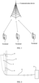
- FIG. 1 is a diagram of an example of a system architecture to which an embodiment of this application is applicable.
- the system architecture includes a communication device and a terminal in a radio access network, and wireless communication may be performed between the communication device and the terminal.
- the embodiment shown in FIG. 1 is described by using an example in which the communication device is a base station.
- the base station may be located in a base station subsystem (base station subsystem, BBS), a terrestrial radio access network (UMTS terrestrial radio access network, UTRAN), or an evolved terrestrial radio access network (evolved universal terrestrial radio access, E-UTRAN), and is configured to perform cell coverage of a radio signal, to implement a connection between a terminal device and a wireless network radio frequency end.
- BBS base station subsystem
- UMTS terrestrial radio access network UTRAN
- E-UTRAN evolved terrestrial radio access network
- the base station may be a base transceiver station (base transceiver station, BTS) in a GSM or CDMA system, may be a NodeB (NodeB, NB) in a WCDMA system, may be an evolved NodeB (evolved NodeB, eNB or eNodeB) in a long term evolution (long term evolution, LTE) system, or may be a radio controller in a cloud radio access network (cloud radio access network, CRAN) scenario.
- BTS base transceiver station
- NodeB NodeB
- eNB evolved NodeB
- LTE long term evolution
- CRAN cloud radio access network
- the base station may be a relay station, an access point, a vehicle-mounted device, a wearable device, a gNodeB in a 5G network, a base station in a future evolved public land mobile network (public land mobile network, PLMN), or the like, for example, a new radio base station.
- PLMN public land mobile network
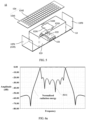
- FIG. 2 is a diagram of a structure of the base station according to an embodiment of this application.
- the base station includes structures such as an active antenna unit (active antenna unit, AAU) 1, a pole 2, and an antenna adjustment bracket 3.
- the active antenna unit 1 may be disposed in a radome 4.
- the radome 4 has a good electromagnetic wave penetration feature in terms of electrical performance, and can withstand impact of an external harsh environment in terms of mechanical performance, thereby protecting the AAU from impact of the external environment.
- the radome 4 may be mounted on the pole 2 or a tower by using the antenna adjustment bracket 3, to facilitate signal receiving or transmitting of the AAU.
- the communication device may further include a baseband processing unit 5, and the baseband processing unit 5 is located at a remote end of the AAU.
- the AAU may be connected to the baseband processing unit 5 through a cable 6.
- FIG. 3 is a diagram of composition of the AAU according to a possible embodiment of this application.
- the AAU 1 may usually include a radio frequency processing unit 11 and an antenna system.
- the antenna system may include one or more antennas 12.
- the radio frequency processing unit 11 is connected to a feeding structure of each antenna 12.
- the radio frequency processing unit 11 may be configured to: perform frequency selection, amplification, and conversion processing on a signal received by the antenna 12, convert a processed signal into an intermediate frequency signal or a baseband signal, and send the intermediate frequency signal or the baseband signal to the baseband processing unit 5.
- the radio frequency processing unit 11 is configured to: perform up-conversion and amplification processing on an intermediate frequency signal of the baseband processing unit 5, and convert a processed signal into an electromagnetic wave and send the electromagnetic wave by using the antenna 12.
- the baseband processing unit 5 is connected to the radio frequency processing unit 11, and is configured to process the intermediate frequency signal or the baseband signal sent by the radio frequency processing unit 11.
- the antenna system may further include a reflector, and the one or more antennas are separately disposed on the reflector 13.
- the reflector 13 may also be referred to as a floor, an antenna panel, a reflection surface, or the like.
- the antenna 12 receives a signal, the reflector 13 may reflect and aggregate the signal of the antenna 12 on a receiving point.
- the antenna 12 transmits a signal the signal may be transmitted to the reflector 13 and reflected and transmitted by the reflector 13.
- the antenna 12 is usually placed on a surface on a side of the reflector 13.
- the AAU may further include a filter 14.
- the filter 14 is connected between the antenna and the radio frequency processing unit, and is configured to filter a signal transmitted or received by the antenna 12, to suppress electromagnetic energy in a non-operating frequency band, and improve radiation performance of the antenna 12.
- an aperture area allocated to each channel of the antenna system is determined by a quantity of channels and a module size.
- an antenna corresponding to each channel is required to achieve maximum gain performance under a given aperture surface.
- a gain of an antenna is equal to directivity (dB) of a single-channel antenna minus an insertion loss (dB). Therefore, the antenna system needs to achieve high directivity and have a low loss feature, to achieve a high gain.
- a multi-element feature of an antenna is usually implemented in a form of a power division network and a plurality of radiators.
- the antenna and the filter are designed independently, the antenna and the filter need to be cascaded together through a transmission line or a matching circuit to perform impedance matching.
- the additional transmission line or matching circuit increases a size of the entire antenna system, and also causes an additional insertion loss to the antenna. Consequently, an increase in the gain of the antenna is further limited.
- an embodiment of this application provides an antenna, to reduce an insertion loss of the antenna on a premise of achieving high directivity of the antenna, thereby effectively increasing a gain of the antenna.
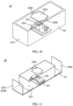
- FIG. 4 is a diagram of a structure of an antenna 12 according to an embodiment of this application.
- the antenna 12 may include a reflector 13, a resonator 121, a radiator 122, an enclosure frame 123, and a phase adjustment structure 124.
- the resonator 121 is disposed on a surface on a side of the reflector 13.
- the radiator 122 is disposed on a side that is of the resonator 121 and that faces away from the reflector 13, and the radiator 122 and the resonator 121 are electrically connected.
- the enclosure frame 123 may be disposed on the side that is of the reflector 13 and on which the resonator 121 and the radiator 122 are disposed, and is connected to the reflector 13, to form an accommodating space to accommodate the resonator 121 and the radiator 122.
- the phase adjustment structure 124 is disposed on a side that is of the enclosure frame 123 and that faces away from the reflector 13, and a projection of the phase adjustment structure 124 onto the surface of the reflector 13 may partially or completely cover a projection of the radiator 122 onto the surface of the reflector 13.
- the reflector 13 may also support and fasten an overall structure of the antenna 12.
- the reflector 13 may be a metal plate, or may be a printed circuit board (printed circuit board, PCB). This is not limited in this application.
- a shape of a cross section of the reflector 13 perpendicular to a thickness direction of the reflector 13 is not limited to a rectangle shown in FIG. 4 .
- the cross section of the reflector 13 may alternatively be a circle, an ellipse, or another regular or irregular shape. This is not limited in this application.
- the resonator 121 may be used as a component of the filter 14 shown in FIG. 3 , to filter a radio frequency signal transmitted or received by the antenna 12, to suppress electromagnetic energy in a non-operating frequency band.
- FIG. 4 shows a case in which there are two resonators 121. In this case, the two resonators 121 may be stacked in a direction away from the reflector 13.
- each resonator 121 may include one or more resonance cavities. Each resonance cavity may provide a first-order filter suppression capability for the antenna 12, that is, filter the electromagnetic energy in the non-operating frequency band of the antenna 12 once.
- quantities of resonance cavities of the resonators 121 may be equal or may be unequal. This is also not limited in this application.
- a quantity of resonators 121 and a quantity of resonance cavities in the resonator 121 may be appropriately designed based on a frequency band of a signal of the antenna 12, to filter out an electromagnetic wave outside the frequency band.
- the resonator 121 may be a dielectric resonator.
- the resonator 121 may be formed by a ceramic dielectric block.
- a main component of the ceramic dielectric block of the resonator 121 includes but is not limited to high dielectric constant ceramics such as barium titanate (BaTiO 3 ), barium carbonate (BaCO 3 ), BaO-Ln 2 O 3 -TiO 3 -2-based microwave dielectric ceramics, or composite perovskite-based microwave dielectric ceramics.
- a high dielectric constant may be understood as a relatively high dielectric constant that may be applied to a dielectric filter.
- the dielectric constant may be greater than 6.
- this application does not exclude a case in which the dielectric constant is less than or equal to 6, provided that a filtering requirement is met.
- all surfaces of the resonator 121 may have metal plating layers.
- the metal plating layer may reduce a risk of energy radiation or leakage in the resonance cavity, thereby helping improve performance of the resonator 121.
- a material of the metal plating layer on the surface of the resonator 121 includes but is not limited to silver, gold, tin, or the like.
- metal plating layers on surfaces of adjacent resonators 121 may be sintered together, to fasten the resonators 121.
- the radiator 122 may also have a resonance property, and can collect and store electromagnetic energy. Therefore, the radiator 122 may also be used as a component of a filter of the antenna 12 to provide a specific frequency selection capability.
- the radiator 122 in this embodiment of this application has both an antenna radiation function and a frequency selection function of the filter.
- the filter and the radiator 122 are integrated and fused, so that an overall structure of the antenna 12 is compact, thereby helping reduce a size of the antenna 12.
- An electrical connection between the radiator 122 and the resonator 121 may be a direct electrical connection (for example, through a probe or a transmission line) or a coupling connection.
- the coupling connection may be understood as a connection manner in which there is no direct electrical contact between the radiator 122 and the resonator 121, but signal energy can be transmitted between the radiator 122 and the resonator 121 through interaction, to implement signal transfer.
- the radiator 122 is simultaneously used by two channels, and each channel corresponds to one signal.
- the antenna 12 provided in this embodiment of this application may be used as a dual-polarized antenna.
- Polarization directions of two signals corresponding to the antenna 12 may be orthogonal, for example, may be +45 degrees and -45 degrees respectively.
- the radiator 122 may respectively radiate electromagnetic energy of the two channels to a space with polarized electromagnetic waves at +45 degrees and -45 degrees.
- the radiator may provide a first-order filter suppression capability for each channel.
- the radiator 122 may be in a form of a dielectric resonator antenna.
- the radiator 122 may be specifically a dielectric resonator formed by a microwave dielectric material with a high dielectric constant.
- a main component of the radiator 122 includes but is not limited to high dielectric constant ceramics such as barium titanate (BaTiO 3 ), barium carbonate (BaCO 3 ), BaO-Ln 2 O 3 -TiO 3 -2-based microwave dielectric ceramics, or composite perovskite-based microwave dielectric ceramics.
- a metal plating layer may be disposed on a surface that is of the radiator 122 and that faces the resonator 121.
- the metal plating layer on the surface of the radiator 122 and a metal plating layer on a surface of the resonator 121 may be sintered together, to relatively fasten the radiator 122 and the resonator 121.
- a surface that is of the radiator 122 and that faces away from the resonator 121 may also have a metal plating layer, and the metal plating layer may partially or completely cover the surface on a side of the radiator 122, to adjust a resonance frequency of the radiator 122.
- a material of the metal plating layer on the surface of the radiator 122 includes but is not limited to silver, gold, tin, or the like.
- no metal plating layer may be disposed on a surface that is of the radiator 122 and that faces away from the resonator 121. This is not limited in this application.
- the radiator 122 may alternatively be implemented by a microstrip resonator.
- the microstrip resonator also has both the frequency selection function of the filter and the radiation performance of the antenna.
- the microstrip resonator may be fastened on the resonator 121 through welding.
- the radiator 122 and the resonator 121 may be electrically connected through a probe.
- the probe (not shown in the figure) may be disposed on the surface that is of the radiator 122 and that faces the resonator 121, and a metallized through hole (not shown in the figure) may be provided at a position that corresponds to the probe and that is on a surface that is of the resonator 121 and that faces the radiator 121. Signal energy is transmitted between the radiator 122 and the resonator 121 through the probe and the metallized through hole.
- the probe may be disposed on a surface that is of the resonator 121 and that faces the radiator 122, and correspondingly, a metalized through hole is provided at a position that corresponds to the probe and that is on the surface that is of the radiator 122 and that faces the resonator 121. In this way, signal transmission between the radiator 122 and the resonator 121 can also be implemented.
- the radiator 122 and the resonator 121 may alternatively be coupled and connected through a gap.
- a first gap (not shown in the figure) may be provided on the surface that is of the radiator 122 and that faces the resonator 121
- a second gap (not shown in the figure) may be provided on a surface that is of the resonator 121 and that faces the radiator 122.
- the first gap may extend in a direction away from the resonator 121
- the second gap may extend in a direction away from the radiator 122
- the first gap is opposite to the second gap.
- Energy coupling is performed between the radiator 122 and the resonator 121 by using the first gap and the second gap.
- Specific forms of the first gap and the second gap may be circular holes, square holes, or hole-shaped structures of another shapes. This is not limited in this application.
- the enclosure frame 123 is a frame-shaped structure that is circumferentially closed and has openings on upper and lower sides.
- the enclosure frame may have a metal surface, and a function of the metal surface is to change, by using reflection performed by a metal conductor on an electromagnetic wave, phases of electromagnetic waves radiated or received by the radiator 122, so that the phases of the electromagnetic waves on an aperture surface of the antenna 12 are close to be consistent, to fully utilize a size of the aperture surface and achieve high directivity of the antenna 12.
- high directivity of the antenna does not need to be achieved in a design form of a plurality of radiators.
- the antenna 12 when only one radiator is disposed, high directivity of the antenna may be achieved by using the enclosure frame. Therefore, no power division network is required. Therefore, an insertion loss of the antenna 12 is also reduced. In combination with the insertion loss reduced in the foregoing coupling connection manner of the radiator 122 and the resonator 121, an overall insertion loss of the antenna 12 may be significantly reduced. That is, the antenna 12 may reduce a loss on a premise of achieving high directivity, thereby increasing a gain.
- the enclosure frame 123 may be of an all-metal structure.
- a material of the enclosure frame may be specifically a metal such as copper or aluminum.
- the enclosure frame 123 may alternatively be made of a plastic material.
- a metal surface may be obtained by performing metallization processing such as coating or electroplating on a surface of the enclosure frame 123.
- a shape of the enclosure frame 123 is not limited to a rectangular frame shown in FIG. 4 .
- the enclosure frame 123 may alternatively be a circular frame, a polygonal frame, or the like, provided that the resonator 121 and the radiator 122 can be enclosed in the enclosure frame 123. This is not limited in this application.
- the phase adjustment structure 124 has a function similar to that of the enclosure frame 123, and may be configured to adjust a phase of an electromagnetic wave transmitted or received by the antenna 12, so that electromagnetic waves are close to expected phase distribution on the aperture surface of the antenna 12, thereby helping achieve high directivity of the antenna 12.
- the phase adjustment structure 124 may be approximately a plate structure.
- the antenna 12 may further include a support column (not shown in the figure). One end of the support column is fastened to the reflector 13, and the other end is fastened to the phase adjustment structure 124, so that the phase adjustment structure 124 is supported above the enclosure frame 123, to relatively fasten the phase adjustment structure 124 and the reflector 13.
- the phase adjustment structure 124 may alternatively be directly fastened on a top of the enclosure frame 123, to help simplify the overall structure of the antenna 12.
- a shape of a cross section of the phase adjustment structure 124 in a direction perpendicular to the reflector 13 is not limited to a rectangle in FIG. 4 .
- a shape of a cross section of the phase adjustment structure 124 may alternatively be a circle, an ellipse, or another regular or irregular shape. This is not limited in this application.
- the phase adjustment structure 124 may include a dielectric substrate 1241 and a metal pattern 1242 disposed on a surface of the dielectric substrate 1241.
- the phase adjustment structure 124 may be manufactured by using a printed circuit board (printed circuit board, PCB) manufacturing process.
- the metal pattern 1242 may be disposed on a side that is of the dielectric substrate 1241 and that faces the radiator 122, or may be disposed on a side that is of the dielectric substrate 1241 and that faces away from the radiator 122.
- a shape of the metal pattern 1242 on the surface of the dielectric substrate 1241 is appropriately designed, and reflection effect of the metal pattern 1242 on an electromagnetic wave is utilized, that is, when the radiator 122 radiates or receives an electromagnetic wave, a phase of the electromagnetic wave may be adjusted, so that the phase of the electromagnetic wave is close to an expected phase on the aperture surface of the antenna.
- the metal pattern 1242 may be a plurality of rectangular metal patches arranged in an array.
- FIG. 5 is a diagram of a structure of another antenna 12 according to an embodiment of this application.
- the antenna may further include a baffle plate 125.
- the baffle plate 125 may be disposed on an outer side of an enclosure frame 123.
- the baffle plate 125 also has a metal surface, to enhance effect of adjusting an amplitude and a phase of an electromagnetic wave by the enclosure frame 123, thereby helping further improve directivity of the antenna 12.
- there may be two baffle plates 125 namely, a first baffle plate 1251 and a second baffle plate 1252 shown in FIG. 5 .
- the first baffle plate 1251 and the second baffle plate 1252 may be oppositely disposed on a reflector 13.
- the first baffle plate 1251 and the second baffle plate 1252 are respectively disposed on two sides of the enclosure frame 123.
- the first baffle plate 1251 and the second baffle plate 1252 may use an all-metal material, or may use another non-metal material and metal surfaces are obtained through metallization processing. This is not limited in this application.
- a metal sheet 1231 may be further disposed on a side that is of the enclosure frame 123 and that faces away from the reflector 13.
- the metal sheet 1231 may partially cover a top of the enclosure frame 123, to improve cross polarization performance of the antenna 12.
- the metal sheet 1231 may be approximately rectangular, and a first extending portion 1232 and a second extending portion 1233 may be respectively disposed on two opposite sides of the metal sheet 1231.
- the enclosure frame 123 is a rectangular frame
- the first extending portion 1232 and the second extending portion 1233 may be respectively fastened to two opposite side walls of the enclosure frame 123, to relatively fasten the metal sheet 1231 and the enclosure frame 123.
- a manner of fastening the first extending portion 1232 and the second extending portion 1233 to the enclosure frame 123 includes but is not limited to welding.
- a resonator 121 may be a dielectric resonator of a single-layer structure.
- the resonator 121 may include eight resonance cavities, and energy coupling and a connection may be performed between the resonance cavities by using a medium window.
- Two polarization channels of the antenna 12 are defined as a first channel and a second channel respectively.
- four resonance cavities may be used by the first channel of the antenna 12 and provide a fourth-order filter suppression capability for the first channel
- the other four resonance cavities may be used by the second channel of the antenna 12 and provide a fourth-order filter suppression capability for the second channel. That is, the resonators in this embodiment may perform four times of filtering on a signal of the first channel and a signal of the second channel respectively.
- the reflector 13, the enclosure frame 123, and a phase adjustment structure 124 may also form a resonance structure.
- the resonance structure may implement a function similar to that of a Fabry-Pérot resonance cavity, and may simultaneously provide first-order filter suppression capabilities for the two channels of the antenna 12.
- the antenna 12 provided in this embodiment may provide a sixth-order filter suppression capability for each channel.
- FIG. 6a is a curve graph of filtering performance of the antenna 12 shown in FIG. 5 .
- a horizontal coordinate is a frequency
- a vertical coordinate is an amplitude (dB).
- Two curves respectively represent an S11 parameter curve and a normalized radiation energy curve, where S11 is an input reflection coefficient, namely, an input return loss.
- a port reflection coefficient represented by the S11 parameter curve has six poles, and a suppression feature represented by the normalized radiation energy curve is consistent with a sixth-order Chebyshev curve.
- a frequency selection function of a sixth-order filter used by an antenna in an existing solution can be implemented by using only four resonance cavities of the resonator 121, and in comparison with the existing solution, a gain obtained after an insertion loss is reduced due to reduction of two resonance cavities can be obtained.
- FIG. 6b is a curve graph of radiation performance of the antenna 12 shown in FIG. 5 .
- a horizontal coordinate is a radiation angle of a signal of the antenna
- a vertical coordinate is an amplitude (dB).
- Four curves respectively represent directions of horizontal plane main polarization, horizontal plane cross polarization, vertical plane main polarization, and vertical plane cross polarization of the antenna. It can be seen from FIG.
- an angle of the vertical plane main polarization is clearly narrower than an angle of the horizontal plane main polarization, that is, a beam width of the antenna in a vertical plane is narrower than a beam width of the antenna in a horizontal plane
- effect is equivalent to that of a conventional three-element array antenna solution, that is, the antenna provided in this embodiment of this application implements effect similar to that of a three-element array antenna. Because no power division network is required in this solution, a gain obtained after an insertion loss is reduced due to removal of the power division network can be obtained on a premise that directivity equivalent to that of the current three-element array antenna is achieved.
- FIG. 7 is a diagram of a structure of another antenna 12 according to an embodiment of this application.
- the antenna 12 may include two phase adjustment structures 124, and the two phase adjustment structures 124 may be sequentially stacked in a direction away from a reflector 13.
- arrangement densities of metal patterns on the two phase adjustment structures may be sparse, so that electromagnetic waves on an aperture surface of the antenna 12 are adjusted to equal phases through electromagnetic wave transmission of a region that is on dielectric substrates and that is other than the metal patterns, thereby achieving high directivity of the antenna 12.
- the antenna 12 provided in this embodiment can also implement radiation performance similar to that of a three-element array antenna.
- the upper and lower phase adjustment structures 124 may be disposed at intervals, and may be separately supported and fastened on the reflector 13 by using different support columns.
- shapes of the metal patterns of the two phase adjustment structures 124 may be the same or different. Specifically, the shapes of the metal patterns may be designed according to an actual requirement of the antenna 12. This is not limited in this application.
- a case in which there are one or two phase adjustment structures 124 is described by using an example. It should be understood that in some other embodiments, there may be three or more phase adjustment structures 124.
- the plurality of phase adjustment structures 124 may be sequentially stacked in the direction away from a reflector 13, and an appropriate support manner is selected with reference to a case of the foregoing two phase adjustment structures 124, to support and fasten the plurality of phase adjustment structures 124. Details are not described herein again.
- FIG. 8 is a diagram of a structure of another phase adjustment structure 124 according to an embodiment of this application.
- the phase adjustment structure 124 is made of a dielectric material as a whole, and different regions of the phase adjustment structure 124 are designed to have different thicknesses, to implement phase adjustment of an electromagnetic wave radiated or received by a radiator, so that phases of electromagnetic waves on an aperture surface of the antenna are close to be consistent.
- a thickness of the phase adjustment structure 124 may be understood as a size of the phase adjustment structure 124 in a direction perpendicular to the reflector.
- the thickness of the phase adjustment structure 124 may gradually decrease in a direction from a center of the phase adjustment structure 124 to an edge of the phase adjustment structure 124. That is, the phase adjustment structure 124 may be approximately thick in a middle and thin at the edge. The phase adjustment structure 124 with such thickness distribution can better adjust a phase of an electromagnetic wave. This helps further improve directivity of the antenna.
- the thickness of the phase adjustment structure 124 may gradually decrease in a step-like manner in the direction from the center of the phase adjustment structure 124 to the edge of the phase adjustment structure 124.
- the phase adjustment structure 124 may be considered as including a plurality of ring structures 1243. The plurality of ring structures 1243 are sequentially arranged in the direction from the center to the edge, and in the arrangement direction, thicknesses of the ring structures 1243 sequentially decrease.
- the thickness of the phase adjustment structure may decrease linearly in the direction from the center of the phase adjustment structure to the edge of the phase adjustment structure.
- a surface on which the center of the phase adjustment structure points to the edge of the phase adjustment structure is of a downward inclined plane structure.
- the thickness of the phase adjustment structure may gradually decrease in an arc-shape manner in the direction from the center of the phase adjustment structure to the edge of the phase adjustment structure.
- a surface on which the center of the phase adjustment structure points to the edge of the phase adjustment structure is of a downward inclined curved surface structure.
- FIG. 9 is a diagram of a structure of another antenna 12 according to an embodiment of this application.
- a resonator 121 may be a metal cavity resonator.
- the resonator 121 may include a metal housing 1211 and a metal resonance rod (not shown in the figure) disposed in the metal housing 1211.
- an interval between a primary mode resonance frequency and a higher-order mode resonance frequency of the antenna 12 can be expanded, thereby improving high-end suppression performance of the resonator 121.
- the plurality of resonators 121 may be disposed at a same layer on a reflector.
- the plurality of resonators 121 may be distributed at a plurality of layers, and each layer may include one or more resonators 121 disposed in an array. Each resonator 121 may provide a first-order filter suppression capability for the antenna 12.
- components such as a radiator 122, an enclosure frame 123, a phase adjustment structure 124, and a baffle plate 125 may be designed with reference to any one of the foregoing embodiments. Details are not described herein again.
- the antenna 12 provided in this embodiment can implement radiation performance similar to that of a three-element array antenna.
- FIG. 10 is a diagram of a structure of another antenna 12 according to an embodiment of this application.
- the antenna 12 may include a reflector 13, a resonator 121, a radiator 122, and an enclosure frame 123.
- the resonator 121 is disposed on a surface on a side of the reflector 13
- the radiator 122 is disposed on a side that is of the resonator 121 and that faces away from the reflector 13, and the radiator 122 and the resonator 121 are electrically connected.
- the enclosure frame 123 may be disposed on the side that is of the reflector 13 and on which the resonator 121 and the radiator 122 are disposed, and is connected to the reflector 13, to form an accommodating space to accommodate the resonator 121 and the radiator 122.
- structures of the reflector 13, the resonator 121, the radiator 122, and the enclosure frame 123 may be set with reference to any one of the foregoing embodiments. Details about these components are not described herein again.
- a difference from the foregoing embodiment is that, a phase adjustment structure is omitted from the antenna in this embodiment of this application. Therefore, a phase adjustment function is mainly implemented by the enclosure frame 123. Phases of electromagnetic waves radiated or received by the antenna are changed by using reflection effect of a metal surface of the enclosure frame 123 on an electromagnetic wave, so that the phases of the electromagnetic waves on an aperture surface of the antenna 12 are close to be consistent, to utilize a size of the aperture surface to a maximum extent and achieve high directivity of the antenna 12.
- a loss of the antenna 12 is also reduced.
- an overall loss of the antenna 12 may be significantly reduced. That is, the antenna 12 may reduce a loss on a premise of achieving high directivity, thereby increasing a gain.
- a cross-sectional height of the antenna 12 is relatively low. This facilitates mounting of the antenna 12 in a communication device.
- a metal sheet 1231 may be further disposed on a side that is of the enclosure frame 123 and that faces away from the reflector 13.
- the metal sheet 1231 may partially cover a top of the enclosure frame 123, to improve cross polarization performance of the antenna 12.
- the metal sheet 1231 may be approximately rectangular, and a first extending portion 1232 and a second extending portion 1233 may be respectively disposed on two opposite sides of the metal sheet 1231.
- the enclosure frame 123 is a rectangular frame
- the first extending portion 1232 and the second extending portion 1233 may be respectively fastened to two opposite side walls of the enclosure frame 123, to relatively fasten the metal sheet 1231 and the enclosure frame 123.
- a manner of fastening the first extending portion 1232 and the second extending portion 1233 to the enclosure frame 123 includes but is not limited to welding.
- FIG. 11 is a diagram of a structure of another antenna 12 according to an embodiment of this application.
- a first baffle plate 1251 and a second baffle plate 1252 may be disposed on an outer side of an enclosure frame 123.
- Both the first baffle plate 1251 and the second baffle plate 1252 have a metal surface, and the first baffle plate 1251 and the second baffle plate 1252 are oppositely disposed on a reflector 13, to enhance effect of adjusting an amplitude and a phase of an electromagnetic wave by the enclosure frame 123, thereby helping further improve directivity of the antenna 12.
- FIG. 12 is a diagram of a structure of another antenna according to an embodiment of this application.
- the antenna 12 may include a reflector 13, a resonator 121, a radiator 122, and a phase adjustment structure 124.
- the resonator 121 is disposed on a surface on a side of the reflector 13
- the radiator 122 is disposed on a side that is of the resonator 121 and that faces away from the reflector 13
- the radiator 122 and the resonator 121 are electrically connected.
- the phase adjustment structure 124 may be disposed on a side that is of the radiator 122 and that faces away from the reflector 13.
- FIG. 12 shows a specific structure obtained when the phase adjustment structure 124 uses a combination form of a dielectric substrate 1241 and a metal pattern 1242.
- a phase adjustment function is mainly implemented by the phase adjustment structure 124.
- the phase adjustment structure 124 adjusts phases of electromagnetic waves on an aperture surface of the antenna 12 to be approximately equal, to utilize a size of the aperture surface to a maximum extent and achieve high directivity of the antenna.
- a loss of the antenna 12 is also reduced.
- an overall loss of the antenna 12 may be significantly reduced. That is, the antenna 12 may reduce a loss on a premise of achieving high directivity, thereby increasing a gain.
- the enclosure frame is omitted, an overall weight of the antenna 12 is reduced.
- FIG. 13 is a diagram of a structure of another antenna 12 according to an embodiment of this application. As shown in FIG. 13 , an enclosure frame is also omitted from the antenna 12 in this embodiment.
- a resonator 121, a radiator 122, and a phase adjustment structure 124 still refer to setting manners in any one of the foregoing embodiments.
- Another specific structure obtained when the phase adjustment structure 124 uses a combination form of a dielectric substrate 1241 and a metal pattern 1242 is shown herein.
- FIG. 14 is a diagram of a structure of another antenna 12 according to an embodiment of this application. As shown in FIG. 14 , an enclosure frame is also omitted from the antenna in this embodiment. For designs of a reflector 13, a resonator 121, a radiator 122, and a phase adjustment structure 124, still refer to setting manners in any one of the foregoing embodiments. A specific structure obtained when the phase adjustment structure is made of an all-dielectric material is shown herein.
- the antenna 12 provided in this embodiment can implement radiation performance similar to that of a quad-element array antenna.
Landscapes
- Engineering & Computer Science (AREA)
- Computer Networks & Wireless Communication (AREA)
- Aerials With Secondary Devices (AREA)
Applications Claiming Priority (1)
| Application Number | Priority Date | Filing Date | Title |
|---|---|---|---|
| PCT/CN2022/117393 WO2024050703A1 (zh) | 2022-09-06 | 2022-09-06 | 一种天线及通信设备 |
Publications (2)
| Publication Number | Publication Date |
|---|---|
| EP4572011A1 true EP4572011A1 (de) | 2025-06-18 |
| EP4572011A4 EP4572011A4 (de) | 2025-10-15 |
Family
ID=90192673
Family Applications (1)
| Application Number | Title | Priority Date | Filing Date |
|---|---|---|---|
| EP22957676.4A Pending EP4572011A4 (de) | 2022-09-06 | 2022-09-06 | Antenne und kommunikationsvorrichtung |
Country Status (4)
| Country | Link |
|---|---|
| US (1) | US20250202107A1 (de) |
| EP (1) | EP4572011A4 (de) |
| CN (1) | CN119816998A (de) |
| WO (1) | WO2024050703A1 (de) |
Family Cites Families (8)
| Publication number | Priority date | Publication date | Assignee | Title |
|---|---|---|---|---|
| US6879287B2 (en) * | 2003-05-24 | 2005-04-12 | Agency For Science, Technology And Research | Packaged integrated antenna for circular and linear polarizations |
| US8823598B2 (en) * | 2011-05-05 | 2014-09-02 | Powerwave Technologies S.A.R.L. | Reflector and a multi band antenna |
| CN103985969B (zh) * | 2014-05-26 | 2016-04-27 | 西安电子科技大学 | 一种介质反射面天线的设计方法 |
| CN212033232U (zh) * | 2020-05-25 | 2020-11-27 | 广州卓德信息科技有限公司 | 一种双u型结构的高前后比天线 |
| CN113937481B (zh) * | 2020-06-29 | 2023-07-18 | 上海华为技术有限公司 | 介质滤波天线、电子设备和天线阵列 |
| CN111883914B (zh) * | 2020-07-13 | 2022-10-18 | 南京理工大学 | 基于siw馈电的具有滤波特性的介质谐振器宽带天线 |
| EP4002589B1 (de) * | 2020-11-24 | 2026-02-25 | Nokia Solutions and Networks Oy | Antennensystem |
| CN113206392B (zh) * | 2021-05-14 | 2022-05-24 | 德州学院 | 一种带内雷达散射截面减缩的微带阵列天线 |
-
2022
- 2022-09-06 WO PCT/CN2022/117393 patent/WO2024050703A1/zh not_active Ceased
- 2022-09-06 EP EP22957676.4A patent/EP4572011A4/de active Pending
- 2022-09-06 CN CN202280099681.4A patent/CN119816998A/zh active Pending
-
2025
- 2025-03-06 US US19/071,959 patent/US20250202107A1/en active Pending
Also Published As
| Publication number | Publication date |
|---|---|
| CN119816998A (zh) | 2025-04-11 |
| EP4572011A4 (de) | 2025-10-15 |
| WO2024050703A1 (zh) | 2024-03-14 |
| US20250202107A1 (en) | 2025-06-19 |
Similar Documents
| Publication | Publication Date | Title |
|---|---|---|
| US20250316891A1 (en) | Base station antennas having at least one grid reflector and related devices | |
| US20240339749A1 (en) | Antenna system and communication device | |
| EP4386983A1 (de) | Antennensystem und basisstationsantennenspeisungssystem | |
| US20240313430A1 (en) | Antenna system and base station antenna feeder system | |
| EP4560829A1 (de) | Antennensystem und basisstation | |
| US20250379363A1 (en) | Antenna element, antenna system, and communication device | |
| US20250174886A1 (en) | Antenna and communication device | |
| EP4572011A1 (de) | Antenne und kommunikationsvorrichtung | |
| EP4401236A1 (de) | Antenne und basisstationsantennenspeisungssystem | |
| KR102952337B1 (ko) | 안테나 레이돔 및 이를 포함하는 전자 장치 | |
| CN116266673A (zh) | 一种天线和通信设备 | |
| CN116130904B (zh) | 移相器、天线及基站天馈系统 | |
| CN116073113B (zh) | 一种多频天线及通信设备 | |
| US20260045688A1 (en) | Antenna apparatus, antenna system, and communication device | |
| US20250055178A1 (en) | Base station antenna and base station | |
| WO2025026325A1 (zh) | 一种天线振子、天线及通信设备 | |
| WO2025241695A1 (zh) | 天线系统、基站和终端 | |
| WO2024131483A1 (zh) | 一种馈电装置、天线装置及通信设备 | |
| WO2025025851A1 (zh) | 一种天线和通信设备 | |
| WO2025247220A1 (zh) | 一种天线、通信设备和通信系统 | |
| WO2025167298A1 (zh) | 一种滤波天线、天馈系统、基站以及通信系统 | |
| WO2024104027A1 (zh) | 一种天线及基站 | |
| EP4693726A1 (de) | Filtervorrichtung, kombinationsvorrichtung, antenne und basisstation | |
| WO2025241932A1 (zh) | 天线单元、天线、天线系统及基站 | |
| WO2025026075A1 (zh) | 一种天线振子、天线及通信设备 |
Legal Events
| Date | Code | Title | Description |
|---|---|---|---|
| STAA | Information on the status of an ep patent application or granted ep patent |
Free format text: STATUS: THE INTERNATIONAL PUBLICATION HAS BEEN MADE |
|
| PUAI | Public reference made under article 153(3) epc to a published international application that has entered the european phase |
Free format text: ORIGINAL CODE: 0009012 |
|
| STAA | Information on the status of an ep patent application or granted ep patent |
Free format text: STATUS: REQUEST FOR EXAMINATION WAS MADE |
|
| 17P | Request for examination filed |
Effective date: 20250310 |
|
| AK | Designated contracting states |
Kind code of ref document: A1 Designated state(s): AL AT BE BG CH CY CZ DE DK EE ES FI FR GB GR HR HU IE IS IT LI LT LU LV MC MK MT NL NO PL PT RO RS SE SI SK SM TR |
|
| REG | Reference to a national code |
Ref country code: DE Ref legal event code: R079 Free format text: PREVIOUS MAIN CLASS: H01Q0001360000 Ipc: H01Q0019100000 |
|
| A4 | Supplementary search report drawn up and despatched |
Effective date: 20250915 |
|
| RIC1 | Information provided on ipc code assigned before grant |
Ipc: H01Q 19/10 20060101AFI20250909BHEP Ipc: H01Q 9/04 20060101ALI20250909BHEP Ipc: H01Q 15/00 20060101ALI20250909BHEP Ipc: H01Q 15/08 20060101ALI20250909BHEP Ipc: H01Q 19/06 20060101ALI20250909BHEP Ipc: H01Q 1/24 20060101ALN20250909BHEP Ipc: H01P 7/10 20060101ALN20250909BHEP |
|
| DAV | Request for validation of the european patent (deleted) | ||
| DAX | Request for extension of the european patent (deleted) |