EP4572018A1 - Conducteur confectionné et procédé de confection d'un conducteur - Google Patents
Conducteur confectionné et procédé de confection d'un conducteur Download PDFInfo
- Publication number
- EP4572018A1 EP4572018A1 EP24216775.7A EP24216775A EP4572018A1 EP 4572018 A1 EP4572018 A1 EP 4572018A1 EP 24216775 A EP24216775 A EP 24216775A EP 4572018 A1 EP4572018 A1 EP 4572018A1
- Authority
- EP
- European Patent Office
- Prior art keywords
- shaped element
- plate
- cable
- electrically conductive
- base body
- Prior art date
- Legal status (The legal status is an assumption and is not a legal conclusion. Google has not performed a legal analysis and makes no representation as to the accuracy of the status listed.)
- Pending
Links
Images

Classifications
-
- H—ELECTRICITY
- H01—ELECTRIC ELEMENTS
- H01R—ELECTRICALLY-CONDUCTIVE CONNECTIONS; STRUCTURAL ASSOCIATIONS OF A PLURALITY OF MUTUALLY-INSULATED ELECTRICAL CONNECTING ELEMENTS; COUPLING DEVICES; CURRENT COLLECTORS
- H01R4/00—Electrically-conductive connections between two or more conductive members in direct contact, i.e. touching one another; Means for effecting or maintaining such contact; Electrically-conductive connections having two or more spaced connecting locations for conductors and using contact members penetrating insulation
- H01R4/02—Soldered or welded connections
- H01R4/021—Soldered or welded connections between two or more cables or wires
-
- H—ELECTRICITY
- H01—ELECTRIC ELEMENTS
- H01R—ELECTRICALLY-CONDUCTIVE CONNECTIONS; STRUCTURAL ASSOCIATIONS OF A PLURALITY OF MUTUALLY-INSULATED ELECTRICAL CONNECTING ELEMENTS; COUPLING DEVICES; CURRENT COLLECTORS
- H01R24/00—Two-part coupling devices, or either of their cooperating parts, characterised by their overall structure
- H01R24/20—Coupling parts carrying sockets, clips or analogous contacts and secured only to wire or cable
-
- H—ELECTRICITY
- H01—ELECTRIC ELEMENTS
- H01R—ELECTRICALLY-CONDUCTIVE CONNECTIONS; STRUCTURAL ASSOCIATIONS OF A PLURALITY OF MUTUALLY-INSULATED ELECTRICAL CONNECTING ELEMENTS; COUPLING DEVICES; CURRENT COLLECTORS
- H01R13/00—Details of coupling devices of the kinds covered by groups H01R12/70 or H01R24/00 - H01R33/00
- H01R13/02—Contact members
- H01R13/025—Contact members formed by the conductors of a cable end
-
- H—ELECTRICITY
- H01—ELECTRIC ELEMENTS
- H01R—ELECTRICALLY-CONDUCTIVE CONNECTIONS; STRUCTURAL ASSOCIATIONS OF A PLURALITY OF MUTUALLY-INSULATED ELECTRICAL CONNECTING ELEMENTS; COUPLING DEVICES; CURRENT COLLECTORS
- H01R13/00—Details of coupling devices of the kinds covered by groups H01R12/70 or H01R24/00 - H01R33/00
- H01R13/40—Securing contact members in or to a base or case; Insulating of contact members
- H01R13/405—Securing in non-demountable manner, e.g. moulding, riveting
-
- H—ELECTRICITY
- H01—ELECTRIC ELEMENTS
- H01R—ELECTRICALLY-CONDUCTIVE CONNECTIONS; STRUCTURAL ASSOCIATIONS OF A PLURALITY OF MUTUALLY-INSULATED ELECTRICAL CONNECTING ELEMENTS; COUPLING DEVICES; CURRENT COLLECTORS
- H01R24/00—Two-part coupling devices, or either of their cooperating parts, characterised by their overall structure
- H01R24/38—Two-part coupling devices, or either of their cooperating parts, characterised by their overall structure having concentrically or coaxially arranged contacts
-
- H—ELECTRICITY
- H01—ELECTRIC ELEMENTS
- H01R—ELECTRICALLY-CONDUCTIVE CONNECTIONS; STRUCTURAL ASSOCIATIONS OF A PLURALITY OF MUTUALLY-INSULATED ELECTRICAL CONNECTING ELEMENTS; COUPLING DEVICES; CURRENT COLLECTORS
- H01R4/00—Electrically-conductive connections between two or more conductive members in direct contact, i.e. touching one another; Means for effecting or maintaining such contact; Electrically-conductive connections having two or more spaced connecting locations for conductors and using contact members penetrating insulation
- H01R4/02—Soldered or welded connections
- H01R4/029—Welded connections
-
- H—ELECTRICITY
- H01—ELECTRIC ELEMENTS
- H01R—ELECTRICALLY-CONDUCTIVE CONNECTIONS; STRUCTURAL ASSOCIATIONS OF A PLURALITY OF MUTUALLY-INSULATED ELECTRICAL CONNECTING ELEMENTS; COUPLING DEVICES; CURRENT COLLECTORS
- H01R43/00—Apparatus or processes specially adapted for manufacturing, assembling, maintaining, or repairing of line connectors or current collectors or for joining electric conductors
- H01R43/20—Apparatus or processes specially adapted for manufacturing, assembling, maintaining, or repairing of line connectors or current collectors or for joining electric conductors for assembling or disassembling contact members with insulating base, case or sleeve
- H01R43/24—Assembling by moulding on contact members
-
- H—ELECTRICITY
- H01—ELECTRIC ELEMENTS
- H01R—ELECTRICALLY-CONDUCTIVE CONNECTIONS; STRUCTURAL ASSOCIATIONS OF A PLURALITY OF MUTUALLY-INSULATED ELECTRICAL CONNECTING ELEMENTS; COUPLING DEVICES; CURRENT COLLECTORS
- H01R9/00—Structural associations of a plurality of mutually-insulated electrical connecting elements, e.g. terminal strips or terminal blocks; Terminals or binding posts mounted upon a base or in a case; Bases therefor
- H01R9/22—Bases, e.g. strip, block, panel
- H01R9/223—Insulating enclosures for terminals
-
- H—ELECTRICITY
- H01—ELECTRIC ELEMENTS
- H01R—ELECTRICALLY-CONDUCTIVE CONNECTIONS; STRUCTURAL ASSOCIATIONS OF A PLURALITY OF MUTUALLY-INSULATED ELECTRICAL CONNECTING ELEMENTS; COUPLING DEVICES; CURRENT COLLECTORS
- H01R11/00—Individual connecting elements providing two or more spaced connecting locations for conductive members which are, or may be, thereby interconnected, e.g. end pieces for wires or cables supported by the wire or cable and having means for facilitating electrical connection to some other wire, terminal, or conductive member, blocks of binding posts
- H01R11/11—End pieces or tapping pieces for wires, supported by the wire and for facilitating electrical connection to some other wire, terminal or conductive member
- H01R11/28—End pieces consisting of a ferrule or sleeve
-
- H—ELECTRICITY
- H01—ELECTRIC ELEMENTS
- H01R—ELECTRICALLY-CONDUCTIVE CONNECTIONS; STRUCTURAL ASSOCIATIONS OF A PLURALITY OF MUTUALLY-INSULATED ELECTRICAL CONNECTING ELEMENTS; COUPLING DEVICES; CURRENT COLLECTORS
- H01R2201/00—Connectors or connections adapted for particular applications
- H01R2201/26—Connectors or connections adapted for particular applications for vehicles
-
- H—ELECTRICITY
- H01—ELECTRIC ELEMENTS
- H01R—ELECTRICALLY-CONDUCTIVE CONNECTIONS; STRUCTURAL ASSOCIATIONS OF A PLURALITY OF MUTUALLY-INSULATED ELECTRICAL CONNECTING ELEMENTS; COUPLING DEVICES; CURRENT COLLECTORS
- H01R4/00—Electrically-conductive connections between two or more conductive members in direct contact, i.e. touching one another; Means for effecting or maintaining such contact; Electrically-conductive connections having two or more spaced connecting locations for conductors and using contact members penetrating insulation
- H01R4/28—Clamped connections, spring connections
- H01R4/30—Clamped connections, spring connections utilising a screw or nut clamping member
- H01R4/34—Conductive members located under head of screw
Definitions
- the present invention relates to a prefabricated cable, which is particularly designed for use in vehicles, in particular motor vehicles. Furthermore, the invention relates to a method for assembling a cable, which is particularly intended for use in vehicles.
- the assembly of cables is, for example, AT 017 394 U1 , from the DE 10 2021 107 921 B4 , from the DE 297 12 306 U1 , from the US 2021/0119376 A1 , from the DE 10 2019 119 468 A1 , from the WO 2023/024971 A1 , from the US 2022/0224059 A1 or from the DE 10 2022 103 647 A1 known, whereby stranded conductors are provided with corresponding connection options.
- An object of the invention is therefore to create a prefabricated cable and a method for assembling a cable using means that are as simple as possible in terms of construction, with which the connection of round conductors, in particular coaxial conductors, to other electrically conductive contact elements can be realized, so that the lowest possible electrical resistance prevails between this contact.
- a prefabricated cable is described with the following elements, which are not exclusively limited thereto.
- the prefabricated cable has a cable with at least two coaxially arranged conductors, wherein the cable end is stripped. Furthermore, the prefabricated cable has a base body in which the cable with the stripped cable end is arranged, and furthermore at least a first electrically conductive plate-shaped element and a second electrically conductive plate-shaped element. In the base body, at least a first electrically conductive contact socket and a second electrically conductive contact socket are arranged next to one another. arranged.
- the first electrically conductive plate-shaped element extends between the first contact socket and the stripped cable end, wherein one side of the first plate-shaped element is connected to the first contact socket and another side of the first plate-shaped element opposite the first side is materially connected to the stripped cable end.
- the second electrically conductive plate-shaped element extends between the second contact socket and the stripped cable end, wherein one side of the second plate-shaped element is connected to the second contact socket and another side of the second plate-shaped element opposite the first side is materially connected to the stripped cable end.
- the present invention proposes a two-wire cable, in particular a coaxial cable for use in vehicles, which is arranged in a base body.
- Each of the two conductors of the cable is connected to a corresponding contact socket by means of a plate-shaped element, wherein the connection of the cable and the contact socket takes place via the respective plate-shaped element, which plate-shaped element is integrally connected to the cable.
- the two conductors of the cable can be assembled before the cable is bent, i.e., they can be assembled as a whole.
- the contact elements, such as the contact sockets which represent the interface of the cable to, for example, adjacent high-voltage components in the vehicle, can be manufactured together in a single production step.
- the present invention makes it possible to assemble a coaxial cable from conductors made of a rigid light metal. Compared to flat conductors, the use of coaxial conductors leads to lower electromagnetic compatibility (EMC) loads, a simpler bending process, fewer components, and fewer production steps.
- EMC electromagnetic compatibility
- rigid round conductors, in particular rigid coaxial cables can be assembled.
- the base body can be limited to a single component, thus resulting in a reduction in the number of components and thus in costs.
- prefabricated cable refers in particular to the production of ready-to-connect cables, cable bundles, and complete wiring harnesses with connectors, contacts, and terminal sleeves. These cables can be used primarily to supply electrical power to consumers, particularly in motor vehicles.
- a prefabricated cable can, for example, have/represent a connector that can be used with a mating connector, particularly one that is screwed together.
- the mating connector can, for example, be part of a charging socket or a high-voltage storage device.
- two coaxially arranged conductors refers, in particular, to a coaxial line, i.e., a coaxial cable, which consists of at least two coaxially arranged round conductors.
- a line used in the present invention can consist of the following elements: an inner conductor, in particular made of a light metal such as aluminum, which represents, for example, the DC negative conductor, an inner insulation based thereon, an outer conductor, in particular made of a light metal such as aluminum, which represents the DC positive conductor, and further an outer insulation.
- stripped cable end refers specifically to the exposure of the conductive parts of the cable. This means that the two electrically conductive conductors of the cable are stripped of their insulation, allowing contact between these conductors via the remaining components of the pre-assembled cable. Exposing or insulating these conductors can, for example, represent an additional process step in the production of such a pre-assembled cable.
- electrically conductive plate-shaped element can be understood in particular as a flat element which is obtained, for example, by a stamping process
- the plate-shaped element can be a stamped sheet made of an electrically conductive material.
- material-to-material connection can be understood in particular as the contacting of the two corresponding elements, in this case the contacting of the cable, or the exposed cable ends, with the respective plate-shaped element using a method or a manufacturing process that connects these two parts in a material-to-material manner.
- the material-to-material connection is understood as a joining of the two parts by laser welding.
- the conductor used in the prefabricated cable according to the invention is, in particular, an aluminum conductor, which can be contacted by means of a material-to-material connection in order to provide a firm and permanent electrically conductive connection.
- the material aluminum can form an oxide layer on its surface, which, in the case of a purely force-to-material connection, leads to high electrical resistance under unfavorable environmental conditions.
- the present invention relies on a material-to-material connection to the insulated cable ends of the cable.
- the contact sockets can, in particular, be copper sockets.
- the mating contacts in charging sockets or high-voltage storage devices are also typically made of copper and coated with silver. This allows the contact socket to be made of the same material as the mating contacts to prevent corrosion under adverse environmental conditions and ensure low electrical resistance.
- the first contact socket can have a first connection surface and the second contact socket can have a second connection surface, which first and second connection surfaces are aligned in the same direction, wherein the first and second connection surfaces of the contact sockets are arranged next to one another on a plane and/or wherein the plate-shaped elements extend at a distance from one another on a same plane from the contact socket to the stripped line end.
- connection surface refers in particular to the surface that comes into contact with the counterpart during installation, for example, in a motor vehicle. This connection surface is shown in detail in the figures. According to this embodiment, these connection surfaces should be on one plane. If the connection surfaces were not on one plane, the rigid connection created by the coaxial cable could not be screwed to both boxes with the required surface pressure. For this reason, the contact sockets according to the invention are arranged with their connection surfaces on one plane.
- the first contact socket and the first electrically conductive plate-shaped element can be connected to one another by a material fit, in particular by friction welding, wherein the second contact socket and the second electrically conductive plate-shaped element can be connected to one another by a material fit, in particular by friction welding.
- the contact sockets can be pressed with high force against the plate-shaped elements, for example against the stamped sheets, and welded to the end faces by rotation about their own axis.
- a material-fit connection between the plate-shaped elements and the contact sockets enables a secure and firm connection between these two parts, which can withstand the stresses during use.
- the base body can have two opposing openings on the side on which the cable is arranged, which openings are provided to enable access to the stripped cable end, in particular for a material-to-material connection.
- two opposing sides of the base body can be open, i.e. they form opposing openings. These two opposing sides of the base body can be either completely open or partially open, so that a material-to-material connection can be made. This enables access to the cable during the assembly process.
- a material-to-material connection such as laser welding of aluminum, requires a high power density. The laser can shine through the opposing openings through the base body, thus avoiding damage to the base body.
- the prefabricated cable may further comprise a cover for each of the openings for closing the respective opening, which cover each opening is sealed in a liquid-tight manner, wherein the covers can be integrally connected to the base body to seal the openings.
- the sealing of the cover by means of a liquid-tight connection to the base body can be designed as an additional feature.
- the openings of the base body can be sealed tightly to protect the entire system of the prefabricated cable from environmental influences.
- the covers can be connected to the openings of the base body by means of ultrasonic welding or laser welding. If, for example, ultrasonic welding is used to connect the cover to the base body, the same material can be used for both parts, i.e. for the covers and for the base body, so that the investment costs can also be lower.
- the contact socket can further comprise a screw centered therein, which is intended to connect the contact socket to a counterpart.
- each of the contact sockets i.e., the first and also the second contact socket, can each comprise a screw centered therein.
- the contact socket which functions as a plug, can be connected to a counterpart plug, for example, a part of a charging socket or a high-voltage battery.
- a screw connection can be preferable to a pure plug connection, since the contact resistance is lower here and thus a better electrically conductive connection can be provided.
- the first contact socket, which is connected to the first electrically conductive plate-shaped element, and the second contact socket, which is connected to the second electrically conductive plate-shaped element can be completely surrounded by the base body.
- the base body can be manufactured by means of an injection molding process, so that in this injection molding process, the respective contact sockets and the respective electrically conductive plate-shaped elements can be completely overmolded in a single injection molding process step. Because the contact sockets are overmolded together, i.e. simultaneously, the position of the electrical interfaces relative to one another can have very close tolerances and their precise arrangement relative to one another can be ensured. Furthermore, this simplifies the manufacturing process of the prefabricated cable. By using a base body The number of components to be used can be reduced, which also results in a reduction in costs.
- the first plate-shaped element and the second plate-shaped element can be formed from the same material as the two coaxially arranged conductors. If both the plate-shaped elements and the conductors of the cable are formed from the same material, a better material-fit connection can be created between these materials.
- a light metal is selected as the material, such as aluminum.
- the plate-shaped elements of the prefabricated cable are also made of aluminum.
- the plate-shaped elements are made of the same aluminum alloy as the cable to enable a good welded connection; for example, they can be made of the following materials: EN AW-1050 or EN AW-1370. Selecting the same materials can reduce corrosion under unfavorable environmental conditions, so that electrical resistance in this connection remains as low as possible.
- the base body can further comprise a support geometry which is arranged in the base body and which can be configured to support the line when it is inserted into the base body.
- the support geometry is designed such that the line can be easily pushed in and centers itself. This simplifies insertion of the line into the base body and the line can be specifically brought into the correct position using the support geometry.
- the support geometry can be arranged on an inner side of a wall of the base body and extend inwards into the base body, with the line being inserted on an outer side of this wall of the base body. With this configuration, the line is guided within the base body by means of the support geometry and supported in its position, such that the line is brought into the correct position relative to the two plate-shaped elements.
- the support geometry can have insertion chamfers for centering the cable in the base body. This ensures that the cable is guided to the correct position and centered in the base body when inserted. This is particularly true if the cable consists of an inner and an outer round conductor, which in a simplified geometry can be described as a convoluted cylinder. It can be advantageous to provide insertion bevels which also guide the inner conductor of the cable to the correct position for connection to the other elements of the pre-assembled cable.
- a method for assembling a cable in particular for use in a motor vehicle, comprises the following steps: providing the cable with an exposed stripped cable end, providing a first contact socket and a second contact socket, arranging a first electrically conductive plate-shaped element and a second electrically conductive plate-shaped element such that the first electrically conductive plate-shaped element extends between the first contact socket and the stripped cable end, and the second electrically conductive plate-shaped element extends between the second contact socket and the stripped cable end, connecting the first contact socket and one side of the first plate-shaped element, connecting the second contact socket and one side of the second plate-shaped element, enclosing the outer side of the contact sockets, the first and second plate-shaped elements and the cable with a plastic material to form a base body, materially connecting another side of the first plate-shaped element to the stripped cable end, materially connecting another side of the second plate-shaped element to the stripped cable end.
- the steps are not limited to the above-mentioned order of steps, but the above-mentioned order represents a preferred embodiment of the method. However, further method steps may be added or other method steps may be removed, or existing method steps may be subdivided.
- the method can, for example, proceed as follows.
- the electrically conductive components i.e. the line, the first contact socket, the second contact socket and the electrically conductive plate-shaped elements are provided and arranged such that the electrically conductive plate-shaped elements can provide contact between the respective contact socket and the respective conductor of the line.
- Each of the contact sockets is connected to one side of a plate-shaped element. After the alignment and connection of the contact sockets to the plate-shaped elements, these are formed by forming the base body from flat This is then enclosed. The other side of the respective plate-shaped elements is then firmly bonded to the stripped cable end, i.e., to the respective conductor of the cable.
- the stripped cable end can be connected to the first electrically conductive plate-shaped element and the stripped cable end can be connected to the second electrically conductive plate-shaped element by means of laser welding.
- An ideal connection of soft metals, in particular aluminum as a conductor, to other electrically conductive metals is possible with a material-to-material connection.
- Aluminum forms an oxide layer on the surface, which would lead to high electrical resistance if the connection were made without force under unfavorable ambient conditions.
- the challenge with welding is that the heat introduced can damage the internal insulation of the conductors, in particular of the coaxial cable.
- the melting point of aluminum, at 660 °C is many times higher than the maximum permissible temperature of common insulator materials, which is approximately 120-100 °C.
- connection of the first contact socket to the first electrically conductive plate-shaped element and the connection of the second contact socket to the second electrically conductive plate-shaped element can be carried out by means of friction welding.
- the step of enclosing the outer side of the contact sockets, the first and second plate-shaped elements, and the lead can comprise enclosing by injection molding.
- overmold-ing all Components can ensure safe and permanent alignment of the components at the corresponding component position on the configured line.
- Fig. 1 shows a part of a prefabricated cable 100 according to an exemplary embodiment of the invention.
- the cable 106 here with a dashed arrow and not shown in detail, has at least two coaxially arranged conductors 316, 318 with a stripped cable end.
- the prefabricated cable 100 has: a base body 101, in which the cable 106 with the stripped cable end is arranged, at least one first electrically conductive plate-shaped element 104 and a second electrically conductive plate-shaped element 105.
- the base body 101 at least a first electrically conductive contact socket 102 and a second electrically conductive contact socket 103 are arranged next to one another.
- the two contact sockets 102 and 103 are arranged next to one another with their respective centers on the same imaginary straight line.
- the first electrically conductive plate-shaped element 104 extends between the first contact socket 102 and the stripped line end of the line 106 (not shown here), with one side of the first plate-shaped element 104 being connected to the first contact socket 102 and another side of the first plate-shaped element 104, opposite the first side, being integrally connected to the stripped line end.
- the second electrically conductive plate-shaped element 105 extends between the second contact socket 103 and the stripped line end of the line 106, wherein one side of the second plate-shaped element 105 is connected to the second contact socket 103 and another side of the second plate-shaped element 105 opposite the first side is integrally connected to the stripped line end.
- the base body 101 can extend over two contiguous or connected parts.
- the base body 101 can be divided into two opposing parts, one part having the contact sockets 102, 103 and the other part having the line 106.
- Both parts of the base body 101 are linked by the plate-shaped elements 104, 105 enclosed by the base body 101.
- the plate-shaped elements on the side of the line 106 are exposed in this part of the base body 101 so that they can be connected to the line 106.
- the first contact socket 102 and the first electrically conductive plate-shaped element 104 are connected to one another in a materially bonded manner, in particular by friction welding.
- the second contact socket 103 and the second electrically conductive plate-shaped element 105 are also connected to one another in a materially bonded manner, in particular by friction welding.
- the first contact socket 102, which is connected to the first electrically conductive plate-shaped element 104, and the second contact socket 103, which is connected to the second electrically conductive plate-shaped element 105, are completely surrounded by the base body 101.
- the outer surfaces of the contact sockets 102, 103 and the sides of the plate-shaped elements 104, 105 which abut the contact sockets 102, 103 (and are electrically conductively connected thereto), are surrounded by the base body 101.
- these parts are enclosed by the base body 101 by means of injection molding.
- the plate-shaped elements 104, 105 extend at a distance from one another on the same plane from the respective contact socket 102, 103 to the stripped line end of the line 106 in the base body 101.
- the plate-shaped elements 104, 105 are arranged at the same height and extend together at the same height on a plane between the contact sockets 102, 103 and the line 106 (or the stripped line end).
- the base body 101 has two opposite openings 107 on the side on which the line 106 is arranged.
- the base body 101 is shown from above, which is why only the upper opening 107 is visible.
- the openings 107 are provided to enable access to the stripped cable end, in particular for materially bonding.
- the base body 101 has a support geometry 108, which is arranged in the base body 101 and is configured to support the cable 106 during insertion into the base body 101.
- the support geometry 108 is arranged on an inner side of a wall 109 of the base body 101 and extends inward into the base body 101, wherein the cable 106 is inserted on an outer side of this wall 107 of the base body 101.
- the support geometry 108 has insertion bevels 110 for centering the cable 106 in the base body 101.
- Fig. 2 shows a pre-assembled cable 100 according to an exemplary embodiment of the invention.
- the pre-assembled cable 100 has the same elements as already described with Figure 1 were described.
- the cable 206 is integrated into the base body.
- the cable 206 is sealed by means of a seal 214, in particular a single-wire seal 214. This seal 214 can be pushed onto the cable 206 before it is inserted into the base body 101.
- a cover, a service cover, 213 is provided in the base body 101.
- This service cover 213 is connected to the base body 101 by a folding hinge on one side and by a screw connection on the other side.
- the folding hinge is in the Figure 1 better shown on the left side next to the contact sockets 102, 103.
- the screw connection of the service cover 213 is in Figure 2 now shown on the left side next to the contact sockets 102, 103.
- the pre-assembled cable 100 is made of Figure 2 along the extension direction of the plate-shaped Elements 104, 105 are shown rotated.
- Other locking mechanisms such as those based on plastic clips, can also be used.
- the pre-assembled cable 100 can be disassembled by the service cover 213 allowing access to the individual components of the pre-assembled cable 100.
- a respective cover 212 is shown for closing the respective opening 107, which closes the respective opening 107 in a liquid-tight manner.
- the covers 212 can be connected to the base body 101 in a material-to-material manner to tightly close the openings 107.
- each of the contact sockets 102, 103 has a screw 211 centered therein, which is intended to be able to connect the respective contact socket 102, 103 to a counterpart.
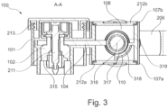
- Fig. 3 shows a sectional view AA of the assembled cable 100 according to an exemplary embodiment of the invention from Figure 2 .
- the pre-assembled cable made of Figure 3 also has all the features that are already associated with the previous Figures 1 and 2 were described. From the Figure 3
- the two opposite openings 107a and 107b with the associated covers 212a and 212b of the base body on the side of the cable 206 can now be removed.
- the extension of the plate-shaped element 104 from the exposed end of the cable 206 to the contact socket 102 is also visible.
- the cable 206 is stripped inside the base body. This means that the inner conductor 316 is exposed and is here in contact with the plate-shaped element 104 and thus electrically connected to the contact socket 102.
- the inner insulation 317 is also exposed, as is the outer conductor 318, which is connected to the other plate-shaped element 105 and the other contact socket 103 (here in Figure 3 (not visible due to the sectional view).
- the outer insulation 319 which marks the beginning of the stripped cable end, is also shown here.
- Both plate-shaped elements 104, 105 are connected to a flat surface on the associated conductor 316, 318 to which they are respectively connected. In the present embodiment, this is preferably done with a short surface on an edge of the plate-shaped elements 104, 105, although this can also be a large surface, such as the top or bottom of the plate-shaped elements 104, 105.
- a short surface has the advantage over the latter that more space remains for assembly activities, such as welding activities.
- connection between a plate-shaped element 104, 105 and the conductor 316, 318 via a flat surface of the respective plate-shaped element 104, 105 also enables simple formation a weld seam or a similar seam serving to form the connection, such as a solder seam, if the conductor 316, 318 is a round conductor and the connection to the flat surface is tangential, since then a natural gusset remains between these two assemblies, which can be used to form the connection if necessary.
- the first contact socket 102 has a first connection surface 315 and the second contact socket 103 also has, but not visible here, a second connection surface, which first and second connection surfaces 315 are aligned in the same direction, wherein the first and second connection surfaces 315 of the contact sockets 102, 103 are arranged next to one another on one plane.
Landscapes
- Engineering & Computer Science (AREA)
- Manufacturing & Machinery (AREA)
- Connections Effected By Soldering, Adhesion, Or Permanent Deformation (AREA)
- Connector Housings Or Holding Contact Members (AREA)
Applications Claiming Priority (1)
| Application Number | Priority Date | Filing Date | Title |
|---|---|---|---|
| DE102023134836.1A DE102023134836A1 (de) | 2023-12-12 | 2023-12-12 | Konfektionierte leitung und verfahren zum konfektionieren einer leitung |
Publications (1)
| Publication Number | Publication Date |
|---|---|
| EP4572018A1 true EP4572018A1 (fr) | 2025-06-18 |
Family
ID=93742567
Family Applications (1)
| Application Number | Title | Priority Date | Filing Date |
|---|---|---|---|
| EP24216775.7A Pending EP4572018A1 (fr) | 2023-12-12 | 2024-12-02 | Conducteur confectionné et procédé de confection d'un conducteur |
Country Status (4)
| Country | Link |
|---|---|
| US (1) | US20250192486A1 (fr) |
| EP (1) | EP4572018A1 (fr) |
| CN (1) | CN119742633A (fr) |
| DE (1) | DE102023134836A1 (fr) |
Citations (10)
| Publication number | Priority date | Publication date | Assignee | Title |
|---|---|---|---|---|
| DE29712306U1 (de) | 1997-07-14 | 1998-11-19 | Minnesota Mining And Mfg. Co., Saint Paul, Minn. | Verlöt- oder Verschweissbarer Kabelverbinder |
| US6428355B1 (en) * | 2000-04-25 | 2002-08-06 | Antaya Technologies Corporation | Coaxial cable assembly |
| US10014600B1 (en) * | 2016-12-20 | 2018-07-03 | Yazaki Corporation | Terminal crimping structure and connector with cable |
| DE102019119468A1 (de) | 2019-04-24 | 2020-10-29 | Metzner Maschinenbau Gmbh | Verfahren, Vorrichtung und System zur Konfektionierung eines elektrischen Kabels |
| US20210119376A1 (en) | 2019-10-17 | 2021-04-22 | Yazaki Corporation | Fitting connector |
| AT17394U1 (de) | 2020-10-29 | 2022-03-15 | Gebauer & Griller Kabelwerke Ges M B H | Kabelanordnung mit gehäuse |
| US20220224059A1 (en) | 2019-06-06 | 2022-07-14 | Autonetworks Technologies, Ltd. | Shield connector |
| WO2023024971A1 (fr) | 2021-08-26 | 2023-03-02 | 长春捷翼汽车零部件有限公司 | Mécanisme de transfert pour transmission d'énergie, douille de charge et véhicule à moteur |
| DE102021107921B4 (de) | 2021-03-29 | 2023-05-17 | Te Connectivity Germany Gmbh | Elektrisches kabel mit an leitern befestigten, separaten kontaktelementen zur bauraumsparenden anordnung in einem stecksystem |
| DE102022103647A1 (de) | 2022-02-16 | 2023-08-17 | Auto-Kabel Management Gmbh | Bordnetzsteckverbinder mit Außenfederung |
Family Cites Families (1)
| Publication number | Priority date | Publication date | Assignee | Title |
|---|---|---|---|---|
| DE102021123635A1 (de) * | 2021-09-13 | 2023-03-16 | Te Connectivity Germany Gmbh | Hochstromverbindungs-Spannschraubenvorrichtung sowie elektrischer Hochstromverbinder und Hochstrom-Leitungsverbinder |
-
2023
- 2023-12-12 DE DE102023134836.1A patent/DE102023134836A1/de active Pending
-
2024
- 2024-12-02 EP EP24216775.7A patent/EP4572018A1/fr active Pending
- 2024-12-11 CN CN202411819883.9A patent/CN119742633A/zh active Pending
- 2024-12-12 US US18/978,768 patent/US20250192486A1/en active Pending
Patent Citations (10)
| Publication number | Priority date | Publication date | Assignee | Title |
|---|---|---|---|---|
| DE29712306U1 (de) | 1997-07-14 | 1998-11-19 | Minnesota Mining And Mfg. Co., Saint Paul, Minn. | Verlöt- oder Verschweissbarer Kabelverbinder |
| US6428355B1 (en) * | 2000-04-25 | 2002-08-06 | Antaya Technologies Corporation | Coaxial cable assembly |
| US10014600B1 (en) * | 2016-12-20 | 2018-07-03 | Yazaki Corporation | Terminal crimping structure and connector with cable |
| DE102019119468A1 (de) | 2019-04-24 | 2020-10-29 | Metzner Maschinenbau Gmbh | Verfahren, Vorrichtung und System zur Konfektionierung eines elektrischen Kabels |
| US20220224059A1 (en) | 2019-06-06 | 2022-07-14 | Autonetworks Technologies, Ltd. | Shield connector |
| US20210119376A1 (en) | 2019-10-17 | 2021-04-22 | Yazaki Corporation | Fitting connector |
| AT17394U1 (de) | 2020-10-29 | 2022-03-15 | Gebauer & Griller Kabelwerke Ges M B H | Kabelanordnung mit gehäuse |
| DE102021107921B4 (de) | 2021-03-29 | 2023-05-17 | Te Connectivity Germany Gmbh | Elektrisches kabel mit an leitern befestigten, separaten kontaktelementen zur bauraumsparenden anordnung in einem stecksystem |
| WO2023024971A1 (fr) | 2021-08-26 | 2023-03-02 | 长春捷翼汽车零部件有限公司 | Mécanisme de transfert pour transmission d'énergie, douille de charge et véhicule à moteur |
| DE102022103647A1 (de) | 2022-02-16 | 2023-08-17 | Auto-Kabel Management Gmbh | Bordnetzsteckverbinder mit Außenfederung |
Also Published As
| Publication number | Publication date |
|---|---|
| DE102023134836A1 (de) | 2025-06-12 |
| CN119742633A (zh) | 2025-04-01 |
| US20250192486A1 (en) | 2025-06-12 |
Similar Documents
| Publication | Publication Date | Title |
|---|---|---|
| DE69812774T2 (de) | Sammelschienenstruktur | |
| DE112011104358B4 (de) | Elektrodraht-Verbindungsaufbau für einen Steckeranschluss und Verfahren zum Herstellen desselben | |
| EP3061153B1 (fr) | Console de connexion électrique et son utilisation | |
| DE102017222352A1 (de) | Anschlusscrimpaufbau und steckverbinder mit kabel | |
| DE102017131352B4 (de) | Leitungsverbinder sowie Herstellverfahren für eine elektrische Verbindung | |
| DE112014002122T5 (de) | Verbinder | |
| DE102018210892B4 (de) | Steckverbindungselement für ein Kraftfahrzeug und Verfahren zum Herstellen eines solchen Steckverbindungselements | |
| DE102017110696A1 (de) | Stromschiene und Verfahren zur Kontaktierung eines elektrischen Motors | |
| DE102004027947B4 (de) | Wasserdichte Konstruktion für ein Erdungs-Anschlußpaßstück, Verfahren und Vorrichtung zum Abdichten eines Erdungs-Anschlußpaßstücks | |
| EP3175204A1 (fr) | Moyen de détection pour véhicule automobile | |
| DE102013013368B4 (de) | Verfahren zur Herstellung einer elektrischen Verbindung sowie elektrische Verbindung | |
| DE102018216965B3 (de) | Verfahren zum Kontaktieren zweier elektrischer Leitungen sowie Steckervorrichtung | |
| EP4572018A1 (fr) | Conducteur confectionné et procédé de confection d'un conducteur | |
| DE102009040343A1 (de) | Verbindungseinheit für eine elektrische Maschine, elektrische Maschine und Getriebe für ein Fahrzeug | |
| DE102019120373B4 (de) | Anschlussanordnung und Fahrzeug | |
| DE102024206230A1 (de) | Hochspannungssteckverbinder und elektromechanische vorrichtung | |
| DE102006011262A1 (de) | Elektrischer Verbinder und Verfahren zu dessen Herstellung | |
| DE102015207628A1 (de) | Gehäuse für eine Zwillingsanordnung von Elektromaschinen und Zwei-Motorenantrieb | |
| DE10159754B4 (de) | Verbinder und Verfahren zum Verbinden eines Drahtes | |
| EP3949029B1 (fr) | Fiche présentant un élément de contact conçu sous forme de pièce coulée | |
| DE102018218527A1 (de) | Gehäusedeckel für eine elektrische Maschine und Verfahren zum Herstellen eines Gehäusedeckels | |
| DE102020129246A1 (de) | Stecker für einen Wechselstromanschluss | |
| EP1919037B1 (fr) | Boîtier et procédé de jonction des parties de boîtier | |
| DE102005043450A1 (de) | Kommutatormotor mit einem elektrisch leitenden Lagerschild | |
| DE102023210553A1 (de) | Kontaktiereinheit einer elektrisch angetriebenen Verdichtereinheit |
Legal Events
| Date | Code | Title | Description |
|---|---|---|---|
| PUAI | Public reference made under article 153(3) epc to a published international application that has entered the european phase |
Free format text: ORIGINAL CODE: 0009012 |
|
| STAA | Information on the status of an ep patent application or granted ep patent |
Free format text: STATUS: THE APPLICATION HAS BEEN PUBLISHED |
|
| AK | Designated contracting states |
Kind code of ref document: A1 Designated state(s): AL AT BE BG CH CY CZ DE DK EE ES FI FR GB GR HR HU IE IS IT LI LT LU LV MC ME MK MT NL NO PL PT RO RS SE SI SK SM TR |
|
| STAA | Information on the status of an ep patent application or granted ep patent |
Free format text: STATUS: REQUEST FOR EXAMINATION WAS MADE |
|
| 17P | Request for examination filed |
Effective date: 20251218 |