EP4572021A1 - Isolationsdurchdringender verbinder - Google Patents
Isolationsdurchdringender verbinder Download PDFInfo
- Publication number
- EP4572021A1 EP4572021A1 EP24218968.6A EP24218968A EP4572021A1 EP 4572021 A1 EP4572021 A1 EP 4572021A1 EP 24218968 A EP24218968 A EP 24218968A EP 4572021 A1 EP4572021 A1 EP 4572021A1
- Authority
- EP
- European Patent Office
- Prior art keywords
- jaw
- sub
- jaws
- connector
- spring element
- Prior art date
- Legal status (The legal status is an assumption and is not a legal conclusion. Google has not performed a legal analysis and makes no representation as to the accuracy of the status listed.)
- Pending
Links
Images




Classifications
-
- H—ELECTRICITY
- H01—ELECTRIC ELEMENTS
- H01R—ELECTRICALLY-CONDUCTIVE CONNECTIONS; STRUCTURAL ASSOCIATIONS OF A PLURALITY OF MUTUALLY-INSULATED ELECTRICAL CONNECTING ELEMENTS; COUPLING DEVICES; CURRENT COLLECTORS
- H01R4/00—Electrically-conductive connections between two or more conductive members in direct contact, i.e. touching one another; Means for effecting or maintaining such contact; Electrically-conductive connections having two or more spaced connecting locations for conductors and using contact members penetrating insulation
- H01R4/28—Clamped connections, spring connections
- H01R4/38—Clamped connections, spring connections utilising a clamping member acted on by screw or nut
- H01R4/42—Clamping area to one side of screw only
-
- H—ELECTRICITY
- H01—ELECTRIC ELEMENTS
- H01R—ELECTRICALLY-CONDUCTIVE CONNECTIONS; STRUCTURAL ASSOCIATIONS OF A PLURALITY OF MUTUALLY-INSULATED ELECTRICAL CONNECTING ELEMENTS; COUPLING DEVICES; CURRENT COLLECTORS
- H01R11/00—Individual connecting elements providing two or more spaced connecting locations for conductive members which are, or may be, thereby interconnected, e.g. end pieces for wires or cables supported by the wire or cable and having means for facilitating electrical connection to some other wire, terminal, or conductive member, blocks of binding posts
- H01R11/11—End pieces or tapping pieces for wires, supported by the wire and for facilitating electrical connection to some other wire, terminal or conductive member
- H01R11/22—End pieces terminating in a spring clip
- H01R11/24—End pieces terminating in a spring clip with gripping jaws, e.g. crocodile clip
-
- H—ELECTRICITY
- H01—ELECTRIC ELEMENTS
- H01R—ELECTRICALLY-CONDUCTIVE CONNECTIONS; STRUCTURAL ASSOCIATIONS OF A PLURALITY OF MUTUALLY-INSULATED ELECTRICAL CONNECTING ELEMENTS; COUPLING DEVICES; CURRENT COLLECTORS
- H01R4/00—Electrically-conductive connections between two or more conductive members in direct contact, i.e. touching one another; Means for effecting or maintaining such contact; Electrically-conductive connections having two or more spaced connecting locations for conductors and using contact members penetrating insulation
- H01R4/24—Connections using contact members penetrating or cutting insulation or cable strands
- H01R4/2404—Connections using contact members penetrating or cutting insulation or cable strands the contact members having teeth, prongs, pins or needles penetrating the insulation
- H01R4/2408—Connections using contact members penetrating or cutting insulation or cable strands the contact members having teeth, prongs, pins or needles penetrating the insulation actuated by clamping screws
-
- H—ELECTRICITY
- H01—ELECTRIC ELEMENTS
- H01R—ELECTRICALLY-CONDUCTIVE CONNECTIONS; STRUCTURAL ASSOCIATIONS OF A PLURALITY OF MUTUALLY-INSULATED ELECTRICAL CONNECTING ELEMENTS; COUPLING DEVICES; CURRENT COLLECTORS
- H01R4/00—Electrically-conductive connections between two or more conductive members in direct contact, i.e. touching one another; Means for effecting or maintaining such contact; Electrically-conductive connections having two or more spaced connecting locations for conductors and using contact members penetrating insulation
- H01R4/24—Connections using contact members penetrating or cutting insulation or cable strands
- H01R4/2416—Connections using contact members penetrating or cutting insulation or cable strands the contact members having insulation-cutting edges, e.g. of tuning fork type
- H01R4/242—Connections using contact members penetrating or cutting insulation or cable strands the contact members having insulation-cutting edges, e.g. of tuning fork type the contact members being plates having a single slot
- H01R4/2425—Flat plates, e.g. multi-layered flat plates
- H01R4/2429—Flat plates, e.g. multi-layered flat plates mounted in an insulating base
- H01R4/2433—Flat plates, e.g. multi-layered flat plates mounted in an insulating base one part of the base being movable to push the cable into the slot
-
- H—ELECTRICITY
- H01—ELECTRIC ELEMENTS
- H01R—ELECTRICALLY-CONDUCTIVE CONNECTIONS; STRUCTURAL ASSOCIATIONS OF A PLURALITY OF MUTUALLY-INSULATED ELECTRICAL CONNECTING ELEMENTS; COUPLING DEVICES; CURRENT COLLECTORS
- H01R4/00—Electrically-conductive connections between two or more conductive members in direct contact, i.e. touching one another; Means for effecting or maintaining such contact; Electrically-conductive connections having two or more spaced connecting locations for conductors and using contact members penetrating insulation
- H01R4/24—Connections using contact members penetrating or cutting insulation or cable strands
- H01R4/2416—Connections using contact members penetrating or cutting insulation or cable strands the contact members having insulation-cutting edges, e.g. of tuning fork type
- H01R4/2445—Connections using contact members penetrating or cutting insulation or cable strands the contact members having insulation-cutting edges, e.g. of tuning fork type the contact members having additional means acting on the insulation or the wire, e.g. additional insulation penetrating means, strain relief means or wire cutting knives
-
- H—ELECTRICITY
- H01—ELECTRIC ELEMENTS
- H01R—ELECTRICALLY-CONDUCTIVE CONNECTIONS; STRUCTURAL ASSOCIATIONS OF A PLURALITY OF MUTUALLY-INSULATED ELECTRICAL CONNECTING ELEMENTS; COUPLING DEVICES; CURRENT COLLECTORS
- H01R4/00—Electrically-conductive connections between two or more conductive members in direct contact, i.e. touching one another; Means for effecting or maintaining such contact; Electrically-conductive connections having two or more spaced connecting locations for conductors and using contact members penetrating insulation
- H01R4/28—Clamped connections, spring connections
- H01R4/48—Clamped connections, spring connections utilising a spring, clip, or other resilient member
- H01R4/4809—Clamped connections, spring connections utilising a spring, clip, or other resilient member using a leaf spring to bias the conductor toward the busbar
- H01R4/48185—Clamped connections, spring connections utilising a spring, clip, or other resilient member using a leaf spring to bias the conductor toward the busbar adapted for axial insertion of a wire end
- H01R4/4819—Clamped connections, spring connections utilising a spring, clip, or other resilient member using a leaf spring to bias the conductor toward the busbar adapted for axial insertion of a wire end the spring shape allowing insertion of the conductor end when the spring is unbiased
- H01R4/4821—Single-blade spring
-
- H—ELECTRICITY
- H01—ELECTRIC ELEMENTS
- H01R—ELECTRICALLY-CONDUCTIVE CONNECTIONS; STRUCTURAL ASSOCIATIONS OF A PLURALITY OF MUTUALLY-INSULATED ELECTRICAL CONNECTING ELEMENTS; COUPLING DEVICES; CURRENT COLLECTORS
- H01R4/00—Electrically-conductive connections between two or more conductive members in direct contact, i.e. touching one another; Means for effecting or maintaining such contact; Electrically-conductive connections having two or more spaced connecting locations for conductors and using contact members penetrating insulation
- H01R4/28—Clamped connections, spring connections
- H01R4/48—Clamped connections, spring connections utilising a spring, clip, or other resilient member
- H01R4/4809—Clamped connections, spring connections utilising a spring, clip, or other resilient member using a leaf spring to bias the conductor toward the busbar
- H01R4/4846—Busbar details
- H01R4/485—Single busbar common to multiple springs
-
- H—ELECTRICITY
- H01—ELECTRIC ELEMENTS
- H01R—ELECTRICALLY-CONDUCTIVE CONNECTIONS; STRUCTURAL ASSOCIATIONS OF A PLURALITY OF MUTUALLY-INSULATED ELECTRICAL CONNECTING ELEMENTS; COUPLING DEVICES; CURRENT COLLECTORS
- H01R9/00—Structural associations of a plurality of mutually-insulated electrical connecting elements, e.g. terminal strips or terminal blocks; Terminals or binding posts mounted upon a base or in a case; Bases therefor
- H01R9/03—Connectors arranged to contact a plurality of the conductors of a multiconductor cable, e.g. tapping connections
- H01R9/031—Connectors arranged to contact a plurality of the conductors of a multiconductor cable, e.g. tapping connections for multiphase cables, e.g. with contact members penetrating insulation of a plurality of conductors
Definitions
- the present invention relates to an insulation-piercing connector which provides the electrical connection between a main electrical cable whose insulation is perforated and at least one secondary electrical cable whose end is stripped.
- a connector can be used, for example, to connect photovoltaic panels to a bus cable.
- An object of the present invention is to provide a connector having a different architecture which ensures, among other things, simplified use and the concentration of a clamping force when piercing a main electrical cable.
- the force used to perform the tightening is applied entirely to the teeth to puncture the sheath of the main electrical cable and not to the secondary electrical cables.
- each sub-jaw is movable in translation between a close position in which the teeth of the two sub-jaws are close to each other and a distant position in which the teeth of the two sub-jaws are distant from each other, and the force exerted by the spring element pushes the sub-jaw into the close position.
- the spring element consists of at least one elastic metal strip.
- the spring element comprises at least one wall having a housing, for each housing, the sub-jaw has a protrusion housed in said housing and edges of the housing define the close and distant positions of the sub-jaw.
- the connector comprises for each sub-jaw, a joint secured to the corresponding jaw, having for each tooth, a tunnel through which said tooth passes, the joint is made of a flexible material.
- the clamping means take the form of a threaded rod and at least one nut, each jaw has a chimney passing through said jaw, the threaded rod is arranged in the chimneys and said at least one nut is screwed onto the threaded rod so as to sandwich the two jaws.
- the connector comprises at least one barrel secured to at least one jaw, made of a flexible material and arranged between the two jaws around the threaded rod.
- the jaw considered comprises two arms, where each arm has a proximal end secured to the jaw and a free distal end, and in the clamped position, the arms are intended to bear against the main electric cable.
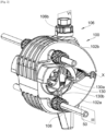
- THE Figs. 1 to 3 show a connector 100 according to the invention in different positions, namely in the spaced apart position at the Fig. 1 , in a tight position at the Fig. 2 and in a tight position and with a main electrical cable 52 to the Fig. 5 .
- the connector 100 thus comprises two jaws 102a-b and each comprising a channel 104a-b in which the main electrical cable 52 is received, which may for example be a bus cable.
- the jaws 102a-b are movable relative to each other between a spread position and a clamped position. In the spread position, the two jaws 102a-b are spread apart to allow free access to the channels 104a-b and to allow the main electrical cable 52 to be placed in the channels 104a-b. In the clamped position, the two jaws 102a-b are brought together to grip and hold the main electrical cable 52.
- the jaws 102a-b are mounted to be movable in rotation relative to each other around an articulation axis X which is generally parallel to an axis of the main electrical cable 52 when the latter is in place.
- the jaws 102a-b are mounted to be movable in translation relative to each other, for example by setting up a sliding connection between them whose translation direction is perpendicular to the axis of the main electrical cable 52 when the latter is in place.
- the connector 100 also includes clamping means 106 which are arranged to hold the jaws 102a-b in a clamped position.
- the clamping means 106 here take the form of a threaded rod 106a and at least one nut 106b screwed onto the threaded rod 106a.
- Each jaw 102a-b is thus crossed by a chimney 120 in which the threaded rod 106a is housed.
- a screw head 106b at one end of the threaded rod 106a and a nut 106b screwed to the other end of the threaded rod 106a and the screw head 106b and the nut 106b bear on a rim of a jaw 102a-b and after tightening the nut 106b, the two jaws are taken sandwiched and tightened between the screw head 106b and the nut 106b.
- Tightening the nut(s) 106b ensures that the jaws 102a-b are clamped together in the clamped position, and loosening the nut(s) 106b ensures that the jaws 102a-b are released, allowing them to move into the spread position.
- each jaw 102a-b comprises two passages 108 which are provided to allow the introduction of a secondary electrical cable 50, which, as explained below, makes it possible to ensure electrical continuity between the main electrical cable 52 and each secondary electrical cable 50.
- at least one jaw 102a-b is equipped with at least one passage 108.
- Each secondary electrical cable 50 is for example a cable from a photovoltaic panel.
- the passage 108 ensures the passage between the exterior and a free space 142 provided inside the jaw 102a-b considered.
- the connector 100 comprises, for each passage 108, a locking system 140 which locks the secondary electrical cable 50 in question.
- the locking system 140 here takes the form of a ring 140a screwed onto the jaw 102a-b and a locking wedge 140b.
- the connector 100 also comprises, for each jaw 102a-b, a sub-jaw 110 which is better seen in Fig. 7 .
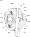
- the sub-jaw 110 is housed in the free space 142 provided for this purpose in the jaw 102a-b and which is better seen on the Figs. 3 And 6 .
- Each sub-jaw 110 has teeth 112 which are made of an electrically conductive material, typically metal, and which are arranged at the channel 104a-b corresponding to said jaw 102a-b.
- the teeth 112 are oriented towards the other sub-jaw 110 and are arranged so that when the jaws 102a-b are in the clamped position, they penetrate into the sheath protecting the main electrical cable 52 in order to establish contact with the conductive part of said main electrical cable 52.
- the connector 100 also comprises for each sub-jaw 110, a spring element 114, preferably made of electrically conductive material.
- the spring element 114 is arranged in the free space 142 and it bears against a wall delimiting the free space 142 of the jaw 102a-b considered.
- the spring element 114 is arranged so as to exert a force against the sub-jaw 110 at a bearing zone 116 of said sub-jaw 110 and it is arranged so as to push the teeth 112 of the sub-jaw 110 towards the teeth 112 of the other sub-jaw 110 to clamp the main electric cable 52 between them and come into contact with its conductive part.
- the passage 108 opens into the free space 142 at the level of the support zone 116 and the spring element 114 so as to allow the insertion of a stripped end of the secondary electrical cable 50 between the support zone 116 and the spring element 114 so that the secondary electrical cable 50 is in contact with the teeth 112 at the level of the support zone 116 and therefore with the main electrical cable 52 through the teeth 112.
- each secondary electrical cable 50 is thus pinched between the spring element 114 and the support zone 116.
- the spring element 114 thus ensures the pressure of the secondary electrical cable 50 against the support zone 116 and therefore the electrical connection with the sub-jaw 110 and therefore the main electrical cable 52.
- such a connector 100 makes it possible to ensure the connection of each secondary electrical cable 50 with the main electrical cable 52. Furthermore, with such an installation, it is possible to prepare the secondary electrical cables 50 in the workshop and when tightening the tightening means 106, the force used to carry out the tightening is entirely applied to the teeth 112 to perforate the sheath of the main electrical cable 52 and not to the secondary electrical cables 50 which therefore do not risk being damaged.
- the jaws 102a-b are made of an electrically insulating material such as polyamide to enclose the sub-jaws 110 and thus prevent leakage currents.
- the spring element 114 is made from a shaped and folded metal spring blade with two metal elastic strips 114a. Generally, there is at least one metal elastic strip 114a. Here, there are two elastic strips 114a to ensure the positioning of a secondary electric cable 50 on each side and to ensure stability of the sub-jaw 110 by pushing at the two support zones 116.
- the sub-jaws 110 are movable in translation, here perpendicular to the axis of the main electric cable 52 when it is in place, between a close position and a distant position.
- the movement of the sub-jaws 110 is limited here, on one side, by a rim 146 produced by the jaw 102a-b where the sub-jaw 110 is housed and, on the other side, by a joint 118 secured to said jaw 102a-b and the primary function of which is explained below.
- the function of the joint 118 of limiting the movement of the sub-jaws 110 can be fulfilled by another rim of the jaw 102a-b arranged for this purpose.
- the teeth 112 of the two sub-jaws 110 are brought together and in the distant position the teeth 112 of the two sub-jaws 110 are moved apart, and the force exerted by the spring element 114 pushes the teeth 112 into the close position.
- the teeth 112 always tend to tighten around the main electrical cable 52 and the mobility of the teeth 112 makes it possible to compensate for any dimensional variations which may appear over time.
- Each contact surface 118b partly delimits the channel 104a-b receiving the main electrical cable 52.
- the connector 100 comprises at least one barrel 122a-b secured to at least one jaw 102a-b and arranged between the two jaws 102a-b around the threaded rod 106a.
- the or each barrel 122a-b is made of a flexible electrically insulating material, so that when the jaws 102a-b move apart or together, the barrel or barrels 122a-b can adapt in length to the distance between the jaws 102a-b.
- each barrel 122a-b for each jaw 102a-b and each barrel 122a-b is in one piece with the seal 118 associated with said jaw 102a-b.
- the jaw 102a-b considered comprises two arms 130, where each arm 130 has a proximal end 130a secured to the jaw 102a-b and a free distal end 130b.
- the arrangement of the arms 130 is such that in the clamped position, the arms 130 bear against the main electrical cable 52.
- the two arms 130 associated with the same jaw 102a-b form a Y, where the ends of the upper branches of the Y are the proximal ends 130a fixed to the jaw 102a-b in a diametrically opposite manner relative to the channel 104a-b, while the middle branch of the Y is constituted by the two distal ends 130b arranged parallel to each other.
Landscapes
- Multi-Conductor Connections (AREA)
- Coupling Device And Connection With Printed Circuit (AREA)
- Details Of Connecting Devices For Male And Female Coupling (AREA)
- Connections By Means Of Piercing Elements, Nuts, Or Screws (AREA)
- Connector Housings Or Holding Contact Members (AREA)
Applications Claiming Priority (1)
| Application Number | Priority Date | Filing Date | Title |
|---|---|---|---|
| FR2314001A FR3156601B1 (fr) | 2023-12-12 | 2023-12-12 | Connecteur à perforation d’isolant |
Publications (1)
| Publication Number | Publication Date |
|---|---|
| EP4572021A1 true EP4572021A1 (de) | 2025-06-18 |
Family
ID=90123180
Family Applications (1)
| Application Number | Title | Priority Date | Filing Date |
|---|---|---|---|
| EP24218968.6A Pending EP4572021A1 (de) | 2023-12-12 | 2024-12-11 | Isolationsdurchdringender verbinder |
Country Status (4)
| Country | Link |
|---|---|
| US (1) | US20250183567A1 (de) |
| EP (1) | EP4572021A1 (de) |
| AU (1) | AU2024278189A1 (de) |
| FR (1) | FR3156601B1 (de) |
Citations (4)
| Publication number | Priority date | Publication date | Assignee | Title |
|---|---|---|---|---|
| ES2296244T3 (es) * | 2003-09-03 | 2008-04-16 | PFISTERER KONTAKTSYSTEME GMBH & CO. KG | Dispositvo para la conexion electrica de, al menos, dos conductores principales aislados de un cable para el suministro de energia, especialmente borna de derivacion. |
| JP4150558B2 (ja) * | 2002-07-16 | 2008-09-17 | ソシエテ アンデュストリエル ドゥ コンストリュクシオン ダパレイユ エ ドゥ マテリエル エレクトリック | 配電架空線路に遠隔設置するための絶縁分岐コネクタ |
| US20100003846A1 (en) * | 2008-07-01 | 2010-01-07 | Fci Americas Technology, Inc. | Electrical Connector |
| US20140220834A1 (en) * | 2013-02-04 | 2014-08-07 | Dynoraxx, Inc. | Solar panel grounding system and clip |
-
2023
- 2023-12-12 FR FR2314001A patent/FR3156601B1/fr active Active
-
2024
- 2024-12-04 US US18/968,759 patent/US20250183567A1/en active Pending
- 2024-12-06 AU AU2024278189A patent/AU2024278189A1/en active Pending
- 2024-12-11 EP EP24218968.6A patent/EP4572021A1/de active Pending
Patent Citations (4)
| Publication number | Priority date | Publication date | Assignee | Title |
|---|---|---|---|---|
| JP4150558B2 (ja) * | 2002-07-16 | 2008-09-17 | ソシエテ アンデュストリエル ドゥ コンストリュクシオン ダパレイユ エ ドゥ マテリエル エレクトリック | 配電架空線路に遠隔設置するための絶縁分岐コネクタ |
| ES2296244T3 (es) * | 2003-09-03 | 2008-04-16 | PFISTERER KONTAKTSYSTEME GMBH & CO. KG | Dispositvo para la conexion electrica de, al menos, dos conductores principales aislados de un cable para el suministro de energia, especialmente borna de derivacion. |
| US20100003846A1 (en) * | 2008-07-01 | 2010-01-07 | Fci Americas Technology, Inc. | Electrical Connector |
| US20140220834A1 (en) * | 2013-02-04 | 2014-08-07 | Dynoraxx, Inc. | Solar panel grounding system and clip |
Also Published As
| Publication number | Publication date |
|---|---|
| FR3156601B1 (fr) | 2025-12-19 |
| US20250183567A1 (en) | 2025-06-05 |
| FR3156601A1 (fr) | 2025-06-13 |
| AU2024278189A1 (en) | 2025-06-26 |
Similar Documents
| Publication | Publication Date | Title |
|---|---|---|
| EP0511111B1 (de) | Elektrische Verbindung und Gehäuse für elektrische Bauteile mit einer solchen Verbindung | |
| FR2463526A1 (fr) | Connecteur de cable a armure metallique sous gaine | |
| CA1222034A (fr) | Prolongateur d'ame d'un cable coaxial, et connecteur muni d'un tel prolongateur | |
| EP0340075B1 (de) | Abzweigklemme zur Verbindung einer isolierten Freileitung mit einer isolierten Abzweigleitung | |
| FR2701170A1 (fr) | Contact électrique femelle à lame souple. | |
| EP0695900B1 (de) | Dichter Durchgang für Fernmeldekabel | |
| EP0893846B1 (de) | Elektrischer Apparat mit einem festen Kontaktträger und einer Anschlussklemme | |
| FR3156601A1 (fr) | Connecteur à perforation d’isolant | |
| EP1912287A1 (de) | Elektrischer Anschluss für Karte mit gedruckter Schaltung und dichtes elektrisches Gehäuse, das einen solchen Anschluss enthält | |
| EP2624365A1 (de) | Elektrische Anschlussklemme | |
| FR2563947A1 (fr) | Agencement de raccordement par borne protegee pour appareillage electrique | |
| EP0452220B1 (de) | Zwischenverbindungseinrichtung für die Kupplung von zwei elektrischen Kabeln ohne Abisolierung | |
| FR2794902A1 (fr) | Connecteur de derivation compact d'au moins un cable de derivation de neutre sur un cable principal de neutre et mise a la terre simultanee | |
| EP0697749A1 (de) | Schnellschneidklemmverbinder | |
| FR2790873A1 (fr) | Connecteur pour cables electriques a perforation d'isolant | |
| EP0172779B1 (de) | Mehrpoliger elektrischer Verbinder | |
| EP4557526B1 (de) | Leistungsanschlussmodul zum klemmen eines elektrischen kabelabschlusses durch ein blatt, dessen mindestens ein verformbares teil zur bildung eines anschlussblockteils einer verbindungsanordnung bildet | |
| FR2578694A1 (fr) | Procede et dispositif pour la connexion des gaines de protection en aluminium des cables de telecommunications | |
| EP0896850B1 (de) | Montagesystem für eine Elektrode in einem Schweissbrenner | |
| FR2619252A1 (fr) | Systeme de liaison a joint pour elements travaillant en hyperfrequence | |
| FR2746687A1 (fr) | Systeme de montage d'electrode dans une torche de soudage | |
| FR2597664A1 (fr) | Dispositif de connexion electrique du type a perforation d'isolant | |
| FR2816764A1 (fr) | Dispositif de raccordement pour deux cables electriques | |
| FR3167774A1 (fr) | Connecteur destiné à la connexion électrique de pôles d’un câble principal de transport d’énergie électrique à des câbles dérivés | |
| FR3157696A1 (fr) | Bouchon à tige pour assurer une fixation de busbarre électrique et une étanchéité |
Legal Events
| Date | Code | Title | Description |
|---|---|---|---|
| PUAI | Public reference made under article 153(3) epc to a published international application that has entered the european phase |
Free format text: ORIGINAL CODE: 0009012 |
|
| STAA | Information on the status of an ep patent application or granted ep patent |
Free format text: STATUS: THE APPLICATION HAS BEEN PUBLISHED |
|
| AK | Designated contracting states |
Kind code of ref document: A1 Designated state(s): AL AT BE BG CH CY CZ DE DK EE ES FI FR GB GR HR HU IE IS IT LI LT LU LV MC ME MK MT NL NO PL PT RO RS SE SI SK SM TR |
|
| STAA | Information on the status of an ep patent application or granted ep patent |
Free format text: STATUS: REQUEST FOR EXAMINATION WAS MADE |
|
| 17P | Request for examination filed |
Effective date: 20251203 |