EP4572036A1 - Connecteur rotatif - Google Patents
Connecteur rotatif Download PDFInfo
- Publication number
- EP4572036A1 EP4572036A1 EP23912121.3A EP23912121A EP4572036A1 EP 4572036 A1 EP4572036 A1 EP 4572036A1 EP 23912121 A EP23912121 A EP 23912121A EP 4572036 A1 EP4572036 A1 EP 4572036A1
- Authority
- EP
- European Patent Office
- Prior art keywords
- core wire
- ring
- gnd
- portions
- connector
- Prior art date
- Legal status (The legal status is an assumption and is not a legal conclusion. Google has not performed a legal analysis and makes no representation as to the accuracy of the status listed.)
- Pending
Links
Images






Classifications
-
- H—ELECTRICITY
- H01—ELECTRIC ELEMENTS
- H01R—ELECTRICALLY-CONDUCTIVE CONNECTIONS; STRUCTURAL ASSOCIATIONS OF A PLURALITY OF MUTUALLY-INSULATED ELECTRICAL CONNECTING ELEMENTS; COUPLING DEVICES; CURRENT COLLECTORS
- H01R39/00—Rotary current collectors, distributors or interrupters
- H01R39/02—Details for dynamo electric machines
- H01R39/08—Slip-rings
-
- H—ELECTRICITY
- H01—ELECTRIC ELEMENTS
- H01R—ELECTRICALLY-CONDUCTIVE CONNECTIONS; STRUCTURAL ASSOCIATIONS OF A PLURALITY OF MUTUALLY-INSULATED ELECTRICAL CONNECTING ELEMENTS; COUPLING DEVICES; CURRENT COLLECTORS
- H01R39/00—Rotary current collectors, distributors or interrupters
- H01R39/64—Devices for uninterrupted current collection
-
- H—ELECTRICITY
- H01—ELECTRIC ELEMENTS
- H01R—ELECTRICALLY-CONDUCTIVE CONNECTIONS; STRUCTURAL ASSOCIATIONS OF A PLURALITY OF MUTUALLY-INSULATED ELECTRICAL CONNECTING ELEMENTS; COUPLING DEVICES; CURRENT COLLECTORS
- H01R2107/00—Four or more poles
-
- H—ELECTRICITY
- H01—ELECTRIC ELEMENTS
- H01R—ELECTRICALLY-CONDUCTIVE CONNECTIONS; STRUCTURAL ASSOCIATIONS OF A PLURALITY OF MUTUALLY-INSULATED ELECTRICAL CONNECTING ELEMENTS; COUPLING DEVICES; CURRENT COLLECTORS
- H01R39/00—Rotary current collectors, distributors or interrupters
- H01R39/02—Details for dynamo electric machines
- H01R39/08—Slip-rings
- H01R39/12—Slip-rings using bearing or shaft surface as contact surface
Definitions
- Patent Document 1 describes a rotary connector device using a conductive ring and a conductive brush.
- Patent Document 1 Japanese Patent Application Publication No. 2013-143183
- the rotary connector may include a case; and a rotor of a cylindrical shape which is arranged in the case to be able to be rotated with respect to the case.
- the rotor may have a plurality of conductive ring portions which respectively correspond to a plurality of channels.
- the rotor may have a plurality of channel barriers arranged respectively between the plurality of conductive ring portions.
- Each of the plurality of conductive ring portions may include a core wire ring.
- Each of the plurality of conductive ring portions may include a first GND ring.
- Each of the plurality of conductive ring portions may include a second GND ring.
- Each of the plurality of conductive ring portions may include a first core wire barrier which is arranged between the core wire ring and the first GND ring.
- Each of the plurality of conductive ring portions may include a second core wire barrier which is arranged between the core wire ring and the second GND ring.
- the case may have a plurality of connector portions which respectively correspond to the plurality of channels.
- Each of the plurality of connector portions may include a connector.
- Each of the plurality of connector portions may include a core wire brush having one end side connected to the connector and another end side in contact with the core wire ring.
- Each of the plurality of connector portions may include a first GND brush having one end side connected to the connector and another end side in contact with the first GND ring.
- Each of the plurality of connector portions may include a second GND brush having one end side connected to the connector and another end side in contact with the second GND ring.
- the first core wire barrier and the second core wire barrier may have shapes in which a leakage radio wave, from the core wire brush in contact with the core wire ring between the first core wire barrier and the second core wire barrier, is hindered from reaching another channel.
- the first core wire barrier may have a shape in which a diameter on a core wire brush side is greater than a diameter on a first GND ring side.
- the second core wire barrier may have a shape in which a diameter on the core wire brush side is greater than a diameter on a second GND ring side.
- a thickness along an axial direction in a cylindrical coordinate system based on the rotor may be a thickness based on characteristic impedance of the corresponding channel; and in the second core wire barrier, a thickness along an axial direction in a cylindrical coordinate system based on the rotor, may be a thickness based on characteristic impedance of the corresponding channel.
- the first core wire barrier may have a shape in which a diameter on the first GND ring side is greater than a diameter on the core wire brush side; and the second core wire barrier may have a shape in which a diameter on the second GND ring side is greater than a diameter on the core wire brush side.
- the rotary connector may further include a plurality of channel barriers which are arranged respectively between the plurality of conductive ring portions, and which are solid GND substrates.
- the case may have an upper surface side portion which corresponds to an upper surface of the rotor, a lower surface side portion which corresponds to a lower surface of the rotor, and a side surface side portion which covers the rotor;
- the plurality of connector portions may be arranged side by side on the side surface side portion;
- the side surface side portion may include a plurality of protrusion portions which correspond to the plurality of connector portions, respectively; and each of the plurality of protrusion portions may include at least one corner portion.
- the plurality of protrusion portions may have a rectangular parallelepiped shape.
- the case may have an upper surface side portion which corresponds to an upper surface of the rotor, a lower surface side portion which corresponds to a lower surface of the rotor, a side surface side portion which covers the rotor, and a plurality of metal partition wall portions which are fixed to the side surface side portion, and each of which separates the conductive ring portions that are adjacent to each other; and the plurality of metal partition wall portions may include hole portions in which the rotor is positioned.
- Each of the plurality of metal partition wall portions may have a size for hindering the leakage radio wave, from the core wire brushes in contact with the core wire rings of the two conductive ring portions that are adjacent to each other, from reaching each other.
- a material of the upper surface side portion, the lower surface side portion, the side surface side portion, and the plurality of metal partition wall portions may be aluminum.
- the plurality of metal partition wall portions may be fixed to the side surface side portion, each of which may separate the conductive ring portions that are adjacent to each other, and may be formed integrally with the side surface side portion.
- the rotary connector may include a case; and a rotor of a cylindrical shape which is arranged to be able to be rotated with respect to the case.
- the rotor may have a plurality of conductive ring portions which respectively correspond to a plurality of channels.
- the rotor may have a plurality of channel barriers arranged respectively between the plurality of conductive ring portions.
- Each of the plurality of conductive ring portions may include a core wire ring.
- Each of the plurality of conductive ring portions may include a first GND ring.
- Each of the plurality of conductive ring portions may include a second GND ring.
- Each of the plurality of conductive ring portions may include a first core wire barrier which is arranged between the core wire ring and the first GND ring.
- Each of the plurality of conductive ring portions may include a second core wire barrier which is arranged between the core wire ring and the second GND ring.
- the case may have a plurality of connector portions which respectively correspond to the plurality of channels.
- Each of the plurality of connector portions may include a connector.
- Each of the plurality of connector portions may include a core wire brush having one end side connected to the connector and another end side in contact with the core wire ring.
- Each of the plurality of connector portions may include a first GND brush having one end side connected to the connector and another end side in contact with the first GND ring.
- Each of the plurality of connector portions may include a second GND brush having one end side connected to the connector and another end side in contact with the second GND ring.
- the case may have an upper surface side portion which corresponds to an upper surface of the rotor.
- the case may have a lower surface side portion which corresponds to a lower surface of the rotor.
- the case may have a side surface side portion which covers the rotor.
- the plurality of connector portions may be arranged side by side on the side surface side portion.
- the side surface side portion may include a plurality of protrusion portions which correspond to the plurality of connector portions, respectively.
- Each of the plurality of protrusion portions may include at least one corner portion.
- the rotary connector may include a case; and a rotor of a cylindrical shape which is arranged to be able to be rotated with respect to the case.
- the rotor may have a plurality of conductive ring portions which respectively correspond to a plurality of channels.
- the rotor may have a plurality of channel barriers arranged respectively between the plurality of conductive ring portions.
- Each of the plurality of conductive ring portions may include a core wire ring.
- Each of the plurality of conductive ring portions may include a first GND ring.
- Each of the plurality of conductive ring portions may include a second GND ring.
- Each of the plurality of conductive ring portions may include a first core wire barrier which is arranged between the core wire ring and the first GND ring.
- Each of the plurality of conductive ring portions may include a second core wire barrier which is arranged between the core wire ring and the second GND ring.
- the case may have a plurality of connector portions which respectively correspond to the plurality of channels.
- Each of the plurality of connector portions may include a connector.
- Each of the plurality of connector portions may include a core wire brush having one end side connected to the connector and another end side in contact with the core wire ring.
- Each of the plurality of connector portions may include a first GND brush having one end side connected to the connector and another end side in contact with the first GND ring.
- Each of the plurality of connector portions may include a second GND brush having one end side connected to the connector and another end side in contact with the second GND ring.
- the case may have an upper surface side portion which corresponds to an upper surface of the rotor.
- the case may have a lower surface side portion which corresponds to a lower surface of the rotor.
- the case may have a side surface side portion which covers the rotor.
- the case may have a plurality of metal partition wall portions which are fixed to the side surface side portion, and each of which separates the conductive ring portions that are adjacent to each other.
- the plurality of metal partition wall portions may include hole portions in which the rotor is positioned.
- a rotary connector 100 contributes to solving such a problem by, for example, carefully considering a barrier shape.
- the rotary connector 100 contributes to solving such a problem by, for example, carefully considering a casing shape.
- Fig. 1 is an illustration for describing a characteristic of a rotary connector.
- Fig. 1 shows examples of a cross sectional shape of a rotary connector, an input waveform to the rotary connector, and an output waveform from the rotary connector.
- a path length of the rotary connector varies with a rotation thereof, to adversely affect a high frequency signal.
- a path length of the rotary connector varies with a rotation thereof, to adversely affect a high frequency signal.
- RF Radio Frequency
- due to the influence there is a physical limitation by the frequency.
- a cross section for the cables to pass through is increased, and it becomes unable to handle the high frequency causing a high attenuation.
- Such a problem is difficult to physically solve, and requires a careful consideration to reduce a reflection and a leakage in another part.
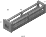
- Fig. 2 , Fig. 3 , and Fig. 4 schematically show examples of the rotary connector 100 according to the present embodiment.
- Fig. 5 schematically shows an example of a structure of the rotary connector 100.
- the rotary connector 100 includes a case 200; and a rotor 300 of a cylindrical shape which is arranged in the case 200 to be able to be rotated with respect to the case 200.
- the rotor 300 has a plurality of conductive ring portions 340 which respectively correspond to a plurality of channels, and a plurality of channel barriers 390 arranged respectively between the plurality of conductive ring portions 340.
- a conductive ring portion 340 includes a core wire ring 350, a GND ring 360, a GND ring 370, a core wire barrier 352 arranged between the core wire ring 350 and the GND ring 360, and a core wire barrier 354 arranged between the core wire ring 350 and the GND ring 370.
- the GND ring 360 may be an example of a first GND ring
- the GND ring 370 may be an example of a second GND ring
- the core wire barrier 352 may be an example of a first core wire barrier
- the core wire barrier 354 may be an example of a second core wire barrier.
- the core wire barrier 352, the core wire barrier 354, and the channel barrier 390 have a disk shape. Lengths of the core wire barrier 352, the core wire barrier 354, and the channel barrier 390, along an axial direction in a cylindrical coordinate system based on the rotor 300, are referred to as thicknesses of the core wire barrier 352, the core wire barrier 354, and the channel barrier 390; and lengths in a radial direction in the cylindrical coordinate system are referred to as diameters of the core wire barrier 352, the core wire barrier 354, and the channel barrier 390.
- the case 200 has an upper surface side portion 210 which corresponds to an upper surface 310 of the rotor 300; a lower surface side portion 220 which corresponds to a lower surface 320 of the rotor 300; and a side surface side portion 230 which covers the rotor 300.
- the case 200 includes a plurality of connector portions 240 which respectively correspond to the plurality of channels.
- a connector portion 240 includes a connector 242, a core wire brush 250, a GND brush 260, and a GND brush 270.
- the connector 242 may be, for example, a so-called SMA (Sub Miniature Type A) connector.
- the core wire brush 250 has one end side connected to the connector 242 and another end side in contact with the core wire ring 350.
- the GND brush 260 has one end side connected to the connector 242 and another end side in contact with the GND ring 360.
- the GND brush 260 may be an example of a first GND brush.
- the GND brush 270 has one end side connected to the connector 242 and another end side in contact with the GND ring 370.
- the GND brush 270 may be an example of a second GND brush.
- the case 200 is constituted by, for example, aluminum.
- the case 200 may be constituted by another metal such as stainless steel.
- the core wire barrier 352 and the core wire barrier 354 are constituted by an insulator.
- the characteristic impedance of each channel depends on the degree of the insulation of the core wire barrier 352 and the core wire barrier 354.
- the thickness of the core wire barrier 352 may be a thickness based on the characteristic impedance of the corresponding channel. That is, the core wire barrier 352 may have a thickness with a degree of the insulation for being able to realize the characteristic impedance of the channel that is set as a target.
- the thickness of the core wire barrier 354 may be a thickness based on the characteristic impedance of the corresponding channel. That is, the core wire barrier 354 may have a thickness with a degree of the insulation for being able to realize the characteristic impedance of the channel that is set as a target.
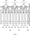
- Fig. 6 is an illustration for describing a characteristic of the rotary connector 100.
- a certain distance or more is required, so that a gap exists.
- the inventor has discovered that when a high voltage is applied to the core wire brush 250, the core wire brush 250 functions as an antenna, and a leakage radio wave occurs.
- the leakage radio wave may adversely affect an adjacent channel, and thus it is desirable to adopt a configuration that reduces the influence of the leakage radio wave.
- Fig. 7 schematically shows an example of the rotary connector 100.
- the core wire barrier 352 and the core wire barrier 354 in the rotary connector 100 may have shapes in which the leakage radio wave, from the core wire brush 250 in contact with the core wire ring 350 between the core wire barrier 352 and the core wire barrier 354, is hindered from reaching another channel.
- the core wire barrier 352 has a shape in which a diameter on a core wire ring 350 side is greater than a diameter on a GND ring 360 side; and the core wire barrier 354 has a shape in which a diameter on the core wire ring 350 side is greater than a diameter on a GND ring 370 side.
- the core wire barrier 352 and the core wire barrier 354 have a wheel shape of a train. That is, each of the core wire barrier 352 and core wire barrier 354 is constituted by a portion of a disk shape having a first diameter and a portion of a disk shape having a second diameter greater than the first diameter.
- the core wire barrier 352 may be configured to have a shape in which the diameter on the GND ring 360 side is greater than the diameter on the core wire ring 350 side; and the core wire barrier 354 may be configured to have a shape in which the diameter on the GND ring 370 side is greater than the diameter on the core wire ring 350 side.
- Fig. 8 schematically shows an example of the rotary connector 100.
- the core wire barrier 352 has a circular truncated cone shape in which a diameter on the core wire ring 350 side is greater than a diameter on the GND ring 360 side; and the core wire barrier 354 has a circular truncated cone shape in which a diameter on the core wire ring 350 side is greater than a diameter on the GND ring 370 side.
- the shape shown in Fig. 8 as well, it is possible to exhibit the effect of reducing the leakage radio wave by the core wire ring 350 while maintaining the characteristic impedance.
- Fig. 9 schematically shows an example of the rotary connector 100.
- Fig. 7 and Fig. 8 show the examples in which while the thicknesses of the core wire barrier 352 and the core wire barrier 354 are maintained, the diameter of a part is increased; however, the present invention is not limited thereto.
- the core wire barrier 352 and the core wire barrier 354 may be configured to have thicknesses and diameters by which the leakage radio wave of the core wire ring 350 is hindered from reaching another channel, while the characteristic impedance that is set as a target is realized.
- Such a thickness and such a diameter are able to be specified, for example, by checking the characteristic impedance while gradually changing the thickness and the diameter for each rotary connector 100.
- Fig. 10 schematically shows an example of the case 200.
- the plurality of connector portions 240 are arranged side by side on the side surface side portion 230 of the case 200.
- the side surface side portion 230 of the case 200 shown in Fig. 10 includes a plurality of protrusion portions 232 which correspond to the plurality of connector portions 240, respectively.
- Each of the plurality of protrusion portions 232 includes at least one corner portion.
- Fig. 10 shows a case where the plurality of protrusion portions 232 have a rectangular parallelepiped shape.
- the inventor has discovered through the experiment that by arranging the protrusion portion 232 having at least one corner portion near the core wire brush 250, the leakage radio wave of the core wire brush 250 is absorbed by the corner portion.
- the protrusion portion 232 By arranging the protrusion portion 232 at a corresponding position for each of the plurality of connector portions 240, it is possible to reduce the influence of the leakage radio wave of the core wire brush 250.
- Fig. 10 shows an example of 14 protrusion portions 232 when there are 14 channels and 14 connector portions 240 are arranged in two rows in a staggered manner.
- the plurality of protrusion portions 232 may be arranged at positions that respectively correspond to the plurality of connector portions 240, in accordance with the number and the arrangement of the connector portions 240.
- the protrusion portion 232 may have a plurality of corner portions on a side surface.
- a side surface side of the protrusion portion 232 may have a jagged shape.
- Fig. 11 schematically shows an example of the structure of the rotary connector 100.
- the case 200 of the rotary connector 100 shown in Fig. 11 has a plurality of metal partition wall portions 234 which are fixed to the side surface side portion 230, and each of which separates the conductive ring portions 340 that are adjacent to each other.
- the metal partition wall portion 234 has a hole portion 236 in which the rotor 300 is positioned. The rotor 300 rotates in the hole portion 236.
- the metal partition wall portion 234 has a size for hindering the leakage radio wave, from the core wire brushes 250 in contact with the core wire rings 350 of the two conductive ring portions 340 that are adjacent to each other, from reaching each other.
- the material of the upper surface side portion 210, the lower surface side portion 220, the side surface side portion 230, and the connector portion 240 may be aluminum.
- the material of the upper surface side portion 210, the lower surface side portion 220, the side surface side portion 230, and the connector portion 240 may be another metal such as stainless steel.
- the metal partition wall portion 234 may be installed in a manner of being fixed to the side surface side portion 230.
- the metal partition wall portion 234 may be formed integrally with the side surface side portion 230.
- the channel barrier 390 has a greater diameter in comparison with that of the channel barrier 390 shown in Fig. 5 . In this manner, by the channel barrier 390, it is possible to hinder the leakage radio wave of the core wire ring 350 from reaching the adjacent channel.
- the channel barrier 390 may be a solid GND substrate. This can make it easy to block or absorb the leakage radio wave. In addition, it is possible to reduce a weight in comparison with a case where the channel barrier 390 is constituted by a metal such as aluminum.
- the rotor 300 which supports the plurality of channels tends to have a long overall length; however, by setting the channel barrier 390 to be light, it is possible to prevent the rotor 300 from bending.
- 100 rotary connector; 200: case; 210: upper surface side portion; 220: lower surface side portion; 230: side surface side portion; 232 protrusion portion; 234 metal partition wall portion; 236 hole portion; 240: connector portion; 242 connector; 250: core wire brush; 260: GND brush; 270: GND brush; 300: rotor; 310: upper surface; 320: lower surface; 340: conductive ring portion; 350: core wire ring; 352 core wire barrier; 354 core wire barrier; 360: GND ring; 370: GND ring; 390: channel barrier.
Landscapes
- Motor Or Generator Current Collectors (AREA)
- Details Of Connecting Devices For Male And Female Coupling (AREA)
Applications Claiming Priority (2)
| Application Number | Priority Date | Filing Date | Title |
|---|---|---|---|
| JP2022208313A JP7271780B1 (ja) | 2022-12-26 | 2022-12-26 | 回転コネクタ |
| PCT/JP2023/046598 WO2024143342A1 (fr) | 2022-12-26 | 2023-12-26 | Connecteur rotatif |
Publications (2)
| Publication Number | Publication Date |
|---|---|
| EP4572036A1 true EP4572036A1 (fr) | 2025-06-18 |
| EP4572036A4 EP4572036A4 (fr) | 2025-12-24 |
Family
ID=86382669
Family Applications (1)
| Application Number | Title | Priority Date | Filing Date |
|---|---|---|---|
| EP23912121.3A Pending EP4572036A4 (fr) | 2022-12-26 | 2023-12-26 | Connecteur rotatif |
Country Status (4)
| Country | Link |
|---|---|
| US (1) | US12470030B2 (fr) |
| EP (1) | EP4572036A4 (fr) |
| JP (1) | JP7271780B1 (fr) |
| WO (1) | WO2024143342A1 (fr) |
Family Cites Families (12)
| Publication number | Priority date | Publication date | Assignee | Title |
|---|---|---|---|---|
| JP2001210430A (ja) | 2000-01-27 | 2001-08-03 | Matsushita Electric Ind Co Ltd | 高周波信号用コネクタ |
| JP4237192B2 (ja) | 2006-03-29 | 2009-03-11 | 日本電産サーボ株式会社 | 摺動リングを用いた接続端子を備えるスリップリング |
| JP4940468B2 (ja) | 2006-11-20 | 2012-05-30 | 多摩川精機株式会社 | スリップリング |
| JP4379821B2 (ja) | 2007-03-29 | 2009-12-09 | 日本航空電子工業株式会社 | 差動伝送コンタクトの製造方法 |
| US7559767B2 (en) * | 2007-05-15 | 2009-07-14 | Moog Inc. | High-frequency drum-style slip-ring modules |
| TWM331247U (en) * | 2007-10-05 | 2008-04-21 | Taiwan Long Hawn Entpr Co | Assembly slip ring |
| JP2012099376A (ja) * | 2010-11-04 | 2012-05-24 | Nidec Servo Corp | スリップリング装置 |
| CN202340044U (zh) | 2011-12-09 | 2012-07-18 | 杭州驰宏科技有限公司 | 多功能滑环 |
| JP5809987B2 (ja) | 2012-01-06 | 2015-11-11 | 日本電産サンキョー株式会社 | 回転コネクタ装置 |
| KR101285280B1 (ko) * | 2013-02-18 | 2013-07-15 | 권성미 | 커넥터가 연결된 전선 꼬임 방지용 로테이터 베어링 |
| JP6253558B2 (ja) | 2014-09-25 | 2017-12-27 | 株式会社東芝 | スリップリング装置 |
| CN113629466B (zh) * | 2021-08-10 | 2024-09-03 | 向雨 | 一种电力滑环 |
-
2022
- 2022-12-26 JP JP2022208313A patent/JP7271780B1/ja active Active
-
2023
- 2023-12-26 EP EP23912121.3A patent/EP4572036A4/fr active Pending
- 2023-12-26 WO PCT/JP2023/046598 patent/WO2024143342A1/fr not_active Ceased
-
2025
- 2025-03-21 US US19/086,175 patent/US12470030B2/en active Active
Also Published As
| Publication number | Publication date |
|---|---|
| US20250219341A1 (en) | 2025-07-03 |
| EP4572036A4 (fr) | 2025-12-24 |
| US12470030B2 (en) | 2025-11-11 |
| JP7271780B1 (ja) | 2023-05-11 |
| WO2024143342A1 (fr) | 2024-07-04 |
| JP2024092410A (ja) | 2024-07-08 |
Similar Documents
| Publication | Publication Date | Title |
|---|---|---|
| CN110731033B (zh) | 具有独立接入的共线天线结构 | |
| US7834271B2 (en) | Cabling having shielding separators | |
| US8460024B2 (en) | Contact assembly for electrical connector | |
| US7622680B2 (en) | Cable jacket with internal splines | |
| JP5454648B2 (ja) | 差動信号用ケーブル及びこれを用いた伝送ケーブル、並びに差動信号用ケーブルの製造方法 | |
| US20110253415A1 (en) | Coaxial Cable with Wire Layer | |
| JP2011086458A (ja) | 差動信号用ケーブル及びこれを用いた伝送ケーブル、並びに差動信号用ケーブルの製造方法 | |
| US20170025203A1 (en) | Cable having improved wires arrangement | |
| US20220254549A1 (en) | A composite cable | |
| CN111029864A (zh) | 一种射频同轴连接器及绝缘支撑 | |
| US8568166B2 (en) | High-voltage coaxial cable and connector | |
| US12470030B2 (en) | Rotary connector | |
| EP3764457A1 (fr) | Guide d'ondes de transmission de signaux à ondes électromagnétiques | |
| CN113381245B (zh) | 用于将线缆与电构件连接的插接连接装置 | |
| US20110174531A1 (en) | Cable with twisted pairs of insulated conductors | |
| US11108181B2 (en) | Vibration resistant high-power electrical connector | |
| EP2784788A1 (fr) | Câble et procédé pour fabriquer un câble | |
| US20200335241A1 (en) | Cable and A Combined Cable | |
| JP5646940B2 (ja) | 電磁波伝送媒体 | |
| EP3246925A1 (fr) | Ligne de transmission de données à paire équilibrée | |
| EP3301750A1 (fr) | Élément de connexion de conducteur creux, système de conducteur creux et procédé de formation de système de conducteur creux | |
| CN103311644A (zh) | 一种可堆积的非接触式宽带高功率旋转铰链及其实现方法 | |
| JP2007110716A (ja) | 複数プレーナ・インダクタ同軸サージ・サプレッサ | |
| CN113488775A (zh) | 一种漏泄电缆及系统 | |
| US20250202155A1 (en) | Connector and Power Device Comprising the Same |
Legal Events
| Date | Code | Title | Description |
|---|---|---|---|
| STAA | Information on the status of an ep patent application or granted ep patent |
Free format text: STATUS: THE INTERNATIONAL PUBLICATION HAS BEEN MADE |
|
| PUAI | Public reference made under article 153(3) epc to a published international application that has entered the european phase |
Free format text: ORIGINAL CODE: 0009012 |
|
| STAA | Information on the status of an ep patent application or granted ep patent |
Free format text: STATUS: REQUEST FOR EXAMINATION WAS MADE |
|
| 17P | Request for examination filed |
Effective date: 20250311 |
|
| AK | Designated contracting states |
Kind code of ref document: A1 Designated state(s): AL AT BE BG CH CY CZ DE DK EE ES FI FR GB GR HR HU IE IS IT LI LT LU LV MC ME MK MT NL NO PL PT RO RS SE SI SK SM TR |
|
| REG | Reference to a national code |
Ref country code: DE Ref legal event code: R079 Free format text: PREVIOUS MAIN CLASS: H01R0039000000 Ipc: H01R0039080000 |
|
| A4 | Supplementary search report drawn up and despatched |
Effective date: 20251120 |
|
| RIC1 | Information provided on ipc code assigned before grant |
Ipc: H01R 39/08 20060101AFI20251114BHEP Ipc: H01R 39/64 20060101ALI20251114BHEP Ipc: H01R 107/00 20060101ALN20251114BHEP |
|
| DAV | Request for validation of the european patent (deleted) | ||
| DAX | Request for extension of the european patent (deleted) |