EP4572045A1 - Traversée de câble - Google Patents
Traversée de câble Download PDFInfo
- Publication number
- EP4572045A1 EP4572045A1 EP23216657.9A EP23216657A EP4572045A1 EP 4572045 A1 EP4572045 A1 EP 4572045A1 EP 23216657 A EP23216657 A EP 23216657A EP 4572045 A1 EP4572045 A1 EP 4572045A1
- Authority
- EP
- European Patent Office
- Prior art keywords
- cable
- clamping element
- support
- opening
- clamping
- Prior art date
- Legal status (The legal status is an assumption and is not a legal conclusion. Google has not performed a legal analysis and makes no representation as to the accuracy of the status listed.)
- Pending
Links
Images


Classifications
-
- H—ELECTRICITY
- H02—GENERATION; CONVERSION OR DISTRIBUTION OF ELECTRIC POWER
- H02G—INSTALLATION OF ELECTRIC CABLES OR LINES, OR OF COMBINED OPTICAL AND ELECTRIC CABLES OR LINES
- H02G3/00—Installations of electric cables or lines or protective tubing therefor in or on buildings, equivalent structures or vehicles
- H02G3/22—Installations of cables or lines through walls, floors or ceilings, e.g. into buildings
-
- H—ELECTRICITY
- H02—GENERATION; CONVERSION OR DISTRIBUTION OF ELECTRIC POWER
- H02G—INSTALLATION OF ELECTRIC CABLES OR LINES, OR OF COMBINED OPTICAL AND ELECTRIC CABLES OR LINES
- H02G15/00—Cable fittings
- H02G15/013—Sealing means for cable inlets
-
- H—ELECTRICITY
- H02—GENERATION; CONVERSION OR DISTRIBUTION OF ELECTRIC POWER
- H02G—INSTALLATION OF ELECTRIC CABLES OR LINES, OR OF COMBINED OPTICAL AND ELECTRIC CABLES OR LINES
- H02G3/00—Installations of electric cables or lines or protective tubing therefor in or on buildings, equivalent structures or vehicles
- H02G3/02—Details
- H02G3/06—Joints for connecting lengths of protective tubing or channels, to each other or to casings, e.g. to distribution boxes; Ensuring electrical continuity in the joint
- H02G3/0616—Joints for connecting tubing to casing
Definitions
- the present invention relates to a cable bushing for passing a cable through an opening in a wall element, with a clamping element which can engage behind an edge of the opening with a locking section, an intermediate support connected to the clamping element, a union nut which can be screwed onto the intermediate support, and a support element for partially supporting the clamping element on an inner side.
- the DE 10 2021 106 864 A1 discloses a cable entry in which a plug-in part that can be inserted into an opening in a wall is provided with locking hooks that are secured against loosening by an inner, sleeve-shaped securing part.
- the securing part also contains a cage formed from webs for a sealing element that can be fixed via a union nut that can be screwed onto a threaded portion of the plug-in part. This allows a cable to be passed through a housing wall in a substantially sealed manner; however, the holding force against tensile stress on the cable is limited.
- the cable entry with the plug-in part can only be mounted on walls with a certain wall thickness.
- the cable feedthrough according to the invention for passing a cable through an opening in a wall element comprises a clamping element which can engage behind an edge of the opening with at least one locking section, an intermediate support connected to the clamping element, a union nut which can be screwed onto the intermediate support and a support element for partially supporting the clamping element on an inner side, wherein the support element is rotatable relative to the clamping element through an angular range of less than 360° in order to move at least one support section of the support element from an unlocked position for mounting the clamping element on the opening in the wall element into a locked position in which the at least one support section supports the locking section of the clamping element on an inner side.
- the support element can be moved axially relative to the tensioning element, allowing the cable entry to be easily mounted on wall elements of different thicknesses.
- the rotational path of the support element relative to the clamping element from an unlocked position to the locked position is between 5° and 90°, in particular between 10° and 50°, so that the locking of the cable duct to the wall element can be carried out with a short movement.
- the support sections move relative to the clamping element preferably between 2 mm and 10 mm in the circumferential direction, which is sufficient for supporting the locking section.
- the tensioning element preferably comprises a ring on which at least two spring bars extending in the axial direction are formed.
- three spring bars are provided, which extend parallel to the axial direction and which surround a channel for the cable feedthrough. Openings are preferably formed between the spring bars, wherein the support element comprises at least one bar to the support section, which extends through such an opening between two spring bars.
- a ring of the support element can then be arranged around the tensioning element and be displaceable relative to it in the axial direction. This outer ring of the support element then extends through the openings between two spring bars and forms a support section, which, in the locked position, supports a locking section on the spring bars on the inside in order to fix the cable feedthrough to the wall element.
- the bars extend at least partially in the axial direction and have an angled section that forms a support section.
- the angled section is, for example, aligned substantially in the circumferential direction.
- the support sections can each be arranged at different positions on the spring bars in the axial direction in order to be able to use the locking mechanism on wall elements of different thicknesses.
- the support element can be latched to the tensioning element in the locked position.
- latching means in the form of latching receptacles and latching projections can be provided on the support element and/or the tensioning element to hold the locked position.
- a first latching hook is provided on the support section and a second latching hook is provided on the inside of a locking section, which can be latched into one another during movement from the unlocked position to the locked position in order to ensure secure fixation of the cable feedthrough.
- Each spring bar of the tensioning element can be latched to a support section.
- the support element can also be latched to the tensioning element in the unlocked position in order to facilitate assembly by latching it in the pre-assembled position.
- the support element can comprise a clamping ring that can be clamped between the intermediate piece and the wall element.
- This allows the support element to be axially positioned via the intermediate piece, wherein the intermediate piece is preferably connected to the tensioning element via a thread.
- the intermediate piece can preferably have an internal thread that is screwed onto an external thread of the tensioning element, resulting in a compact design.
- Such a threaded connection allows the locking sections on the tensioning element and the clamping ring to be positioned at an appropriate distance to adapt to different wall thicknesses.
- the clamping ring does not have to lie directly against the wall element, but can be pressed against the wall element via a sealing ring to achieve improved sealing of the cable feedthrough.
- a sealing ring can also be provided between the tensioning ring and the intermediate piece.
- the clamping element can have a plurality of flexible spring bars which have at least one projection projecting radially outwards, preferably with an insertion bevel, so that the projection can engage behind an edge of the opening of the wall element.
- a cage can be formed in the intermediate piece, in particular a cage with several flexible webs extending in the axial direction, in which an elastic sealing element is accommodated.
- This sealing element can provide a reliable seal when screwing on the union nut, which preferably has a conical bevel for compressing the cage and the sealing element.
- the intermediate socket has an internal thread that can be screwed onto an external thread of the clamping element, whereby the internal thread and the external thread of the intermediate socket overlap each other in the axial direction.
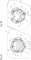
- a cable bushing 1 is used to pass a cable 10, for example with several electrical conductors 11, through a wall element 8, which can be part of a control cabinet or another device.
- the cable bushing 1 comprises a clamping element 2, which can be pushed through an opening in the wall element 8 by means of several spring bars 20, wherein each spring bar 20 has at least one outwardly projecting projection as a locking section 21, which can engage behind an edge of an opening in the wall element 8.
- the clamping element 2 is connected to an intermediate piece 3, in particular via a threaded connection, and a clamping ring 61 of a support element 6 is arranged around the clamping element 2.
- a union nut 4 is screwed onto the intermediate piece 3.
- the cable feedthrough 1 is shown in an exploded view with the individual parts.
- the clamping element 2 comprises a ring 24, from which several spring bars 20 protrude in the axial direction, wherein an opening 23 is formed between each two spring bars 20.
- the spring bar 20 can be bent radially inward by the run-on bevel 22, in order then, after being pushed through the opening 9, to engage behind an edge of the opening 9 with the locking portion 21.
- an external thread 25 is formed which engages with an internal thread 32 of the intermediate socket 3.
- the intermediate connector 3 comprises a cage 30, which is preferably formed from a plurality of circumferentially arranged webs that extend parallel to an axial direction and serve to accommodate a sealing element 5.
- the sealing element 5 can be inserted into the cage 30 of the intermediate connector 3 up to a radially inwardly projecting projection 31 and has a cylindrical opening 50 for the passage of the cable 10.
- the intermediate connector 3 has an external thread 34 on its outer circumference, which overlaps the internal thread 32 in the axial direction, preferably by more than 80%, resulting in a particularly compact design.
- the external thread 34 can have one or more flattened portions 33 distributed over the circumference.
- the union nut 4 which has an internal thread 40 and, adjacent to the internal thread 40, a conical section 41 that opens into an opening 42, is screwed onto the external thread 34 of the intermediate connector 3.
- the union nut 4 is screwed onto the intermediate connector 3, the cage 30 and thus the sealing element 5 can be compressed via the conical section 41 so that it presses against an outer circumference of the cable 10 and seals.
- the support element 6 comprises a clamping ring 61, which can be arranged around the tensioning element 2 and comprises a plurality of webs 60 on the inside. Each web 60 extends through an opening 23 between two spring bars 20 in the mounted position.
- Figure 3 shows a sectional view through a cable entry 1 in the pre-assembled position, in which the components of the cable entry 1 are pre-assembled and arranged next to a wall element 8.
- the support element 6 is arranged around the clamping element 2, and the intermediate piece 3 is screwed onto the clamping element. Furthermore, the union nut 4 is screwed onto the intermediate piece 3 and surrounds the cage 30 with the sealing element 5.
- the cable 10 is passed through the cable entry 1 and the opening 9, and in this position the cable entry 1 with the spring bars 20 can be pushed through the opening 9.
- the spring bars 20 are passed through the wall element, and the outwardly projecting locking sections 21 in the form of projections engage behind the wall element, wherein the wall element 8 is arranged with play between the locking sections 21 and the support element 6.
- the support element 6 can be rotated relative to the tensioning element 2, preferably by an angular range between 5° and 60°, so that the spring bars 20 are supported on the inside via the support element 6. This prevents the spring bars 20 from bending inward, which would require the cable feedthrough 1 to be pulled out of the wall element 8 again.
- the intermediate connector 3 is now screwed into the clamping element 2 until the support element 6 with the clamping ring 61 is clamped between the wall element 8 and the intermediate connector 3.
- the locked position of the cable entry 1 is in the Figures 5A and 5B
- the support element 6 is clamped against the wall element 8 via a sealing ring 7, with one end of the intermediate piece 3 pressing against the clamping ring 61, as can also be seen in the sectional view of the Figure 3 can be removed.
- the locking mechanism of the support element 6 and the clamping element 2 is in the Figures 6A and 6B shown in detail.
- Figure 6A shows a pre-assembled position of the cable feedthrough 1 on the wall element 8 in the unlocked position, in which the spring bars 20 can move radially inward in order to insert the spring bars 20 through the opening 9 or remove them from it.
- the support element 6 comprises the clamping ring 61, from which three bars 60 protrude essentially in the axial direction and pass through the openings 23 between two spring bars 20.
- angled support sections 62 are formed, which extend essentially in the circumferential direction and have a locking projection 63.
- the spring bars 20 have, on an inner side opposite the outer locking sections 21, a locking receptacle 27, which is arranged next to a locking projection 26.
- the support sections 62 have a smaller axial extent than the locking receptacle 27 on the spring bars 20. As a result, with a thicker or thinner wall element 8, the support section 62 can be positioned differently on the respective spring bar 20.
- the union nut 4 is provided with knurling on its outer circumference. It is also possible to provide a different profile instead of the knurling or to form a polygon that can be rotated with a tool.
- the support element 6 also has knurling on its outer circumference, which can optionally be replaced with a different profile or a polygon.
- the intermediate nozzle 3 is screwed onto the clamping element 2 to accommodate different wall thicknesses.
- the intermediate nozzle can also be formed integrally with the clamping element 2.
- the tensioning element 2 has three spring bars 20, and the support element 6 has three bars 60 with support sections 62. It is, of course, also possible to change the number of spring bars 20 and bars 60 depending on the expected loads.
- the cable 10 can be passed through the cable entry 1 without a connector; optionally, a pre-assembled connector can also be passed through the cable entry 1.
- the cable entry 1 can have an adjustment range in the axial direction, which, for example, enables installation on wall thicknesses of 1 mm to 5 mm.
- the cable bushing 1 is used in the embodiment shown for the passage of electrical cables, but can also be used for Can be used to pass through other cables, hoses or lines, for example for liquids or gases.
Landscapes
- Engineering & Computer Science (AREA)
- Architecture (AREA)
- Civil Engineering (AREA)
- Structural Engineering (AREA)
- Installation Of Indoor Wiring (AREA)
Priority Applications (1)
| Application Number | Priority Date | Filing Date | Title |
|---|---|---|---|
| EP23216657.9A EP4572045A1 (fr) | 2023-12-14 | 2023-12-14 | Traversée de câble |
Applications Claiming Priority (1)
| Application Number | Priority Date | Filing Date | Title |
|---|---|---|---|
| EP23216657.9A EP4572045A1 (fr) | 2023-12-14 | 2023-12-14 | Traversée de câble |
Publications (1)
| Publication Number | Publication Date |
|---|---|
| EP4572045A1 true EP4572045A1 (fr) | 2025-06-18 |
Family
ID=89222696
Family Applications (1)
| Application Number | Title | Priority Date | Filing Date |
|---|---|---|---|
| EP23216657.9A Pending EP4572045A1 (fr) | 2023-12-14 | 2023-12-14 | Traversée de câble |
Country Status (1)
| Country | Link |
|---|---|
| EP (1) | EP4572045A1 (fr) |
Citations (3)
| Publication number | Priority date | Publication date | Assignee | Title |
|---|---|---|---|---|
| US3514129A (en) * | 1967-11-09 | 1970-05-26 | Holdren Brothers Inc | Sanitary connector with locking means thereon |
| DE102021106864A1 (de) | 2021-03-19 | 2022-09-22 | CENA-Kunststoff GmbH | Halbverschraubung |
| DE102022104790A1 (de) | 2022-03-01 | 2023-09-07 | CENA-Kunststoff GmbH | Halbverschraubung und Verfahren zur Montage einer Halbverschraubung |
-
2023
- 2023-12-14 EP EP23216657.9A patent/EP4572045A1/fr active Pending
Patent Citations (3)
| Publication number | Priority date | Publication date | Assignee | Title |
|---|---|---|---|---|
| US3514129A (en) * | 1967-11-09 | 1970-05-26 | Holdren Brothers Inc | Sanitary connector with locking means thereon |
| DE102021106864A1 (de) | 2021-03-19 | 2022-09-22 | CENA-Kunststoff GmbH | Halbverschraubung |
| DE102022104790A1 (de) | 2022-03-01 | 2023-09-07 | CENA-Kunststoff GmbH | Halbverschraubung und Verfahren zur Montage einer Halbverschraubung |
Similar Documents
| Publication | Publication Date | Title |
|---|---|---|
| EP2382693B1 (fr) | Dispositif de fixation pour fixer un câble sur un passage de boîtier | |
| EP4060838A1 (fr) | Presse-étoupe | |
| DE102010061067B4 (de) | Vorrichtung zur Fixierung eines Kabels an einen Kabelabgangsstutzen | |
| EP3292602B1 (fr) | Passage de câble/ligne | |
| EP2593995A2 (fr) | Serre-câble | |
| DE202009009807U1 (de) | Manipulationssichere Kabeldurchführung | |
| EP4239233A1 (fr) | Demi-écrou et procédé d'assemblage d'un demi-écrou | |
| EP3301770A1 (fr) | Presse-étoupe | |
| DE29505242U1 (de) | Verbindungsteil für mehradrige Feldbuskabel | |
| EP0780930A2 (fr) | Dispositif d'installation électrique avec un couvercle central | |
| DE3626403A1 (de) | Anschlussarmatur | |
| EP4572045A1 (fr) | Traversée de câble | |
| DE202017006800U1 (de) | Innenliegende Zugentlastung für einen Steckverbinder | |
| EP0695008A1 (fr) | Dispositif de blocage de câble universel | |
| DE202014100429U1 (de) | Elektrisches Anschlusselement sowie Wechselrichter mit einem derartigen elektrischen Anschlusselement | |
| DE29722987U1 (de) | Kabelverschraubung für Kabel mit Abschirmummantelung | |
| DE102023104108A1 (de) | Leiterendkappe | |
| EP4591404A1 (fr) | Élément de contact électrique, insert de connecteur enfichable et connecteur enfichable industriel modulaire le comprenant | |
| EP3598594A1 (fr) | Presse-étoupe | |
| DE102020131734A1 (de) | Leuchtenklemme mit Verschlusstülle | |
| DE102021202556B4 (de) | Anschlussvorrichtung für eine Druckmittelleitung | |
| DE102013007899B4 (de) | Schwenkbarer Verbinder und Verwendung | |
| EP4546582A1 (fr) | Traversée de câble | |
| EP4622017A1 (fr) | Ensemble de terminaison d'un ensemble connecteur de câble, ensemble connecteur de câble et procédé d'assemblage d'un ensemble connecteur de câble | |
| DE102005024440B3 (de) | Kabelanschlußbauteil für eine Kabelanschlußeinrichtung |
Legal Events
| Date | Code | Title | Description |
|---|---|---|---|
| PUAI | Public reference made under article 153(3) epc to a published international application that has entered the european phase |
Free format text: ORIGINAL CODE: 0009012 |
|
| STAA | Information on the status of an ep patent application or granted ep patent |
Free format text: STATUS: THE APPLICATION HAS BEEN PUBLISHED |
|
| AK | Designated contracting states |
Kind code of ref document: A1 Designated state(s): AL AT BE BG CH CY CZ DE DK EE ES FI FR GB GR HR HU IE IS IT LI LT LU LV MC ME MK MT NL NO PL PT RO RS SE SI SK SM TR |
|
| STAA | Information on the status of an ep patent application or granted ep patent |
Free format text: STATUS: REQUEST FOR EXAMINATION WAS MADE |
|
| 17P | Request for examination filed |
Effective date: 20250807 |