EP4572092A1 - Stator pour un moteur électrique - Google Patents
Stator pour un moteur électrique Download PDFInfo
- Publication number
- EP4572092A1 EP4572092A1 EP23216499.6A EP23216499A EP4572092A1 EP 4572092 A1 EP4572092 A1 EP 4572092A1 EP 23216499 A EP23216499 A EP 23216499A EP 4572092 A1 EP4572092 A1 EP 4572092A1
- Authority
- EP
- European Patent Office
- Prior art keywords
- stator
- stator segments
- cage
- segments
- connection
- Prior art date
- Legal status (The legal status is an assumption and is not a legal conclusion. Google has not performed a legal analysis and makes no representation as to the accuracy of the status listed.)
- Pending
Links
Images
Classifications
-
- H—ELECTRICITY
- H02—GENERATION; CONVERSION OR DISTRIBUTION OF ELECTRIC POWER
- H02K—DYNAMO-ELECTRIC MACHINES
- H02K1/00—Details of the magnetic circuit
- H02K1/06—Details of the magnetic circuit characterised by the shape, form or construction
- H02K1/12—Stationary parts of the magnetic circuit
- H02K1/14—Stator cores with salient poles
- H02K1/145—Stator cores with salient poles having an annular coil, e.g. of the claw-pole type
Definitions
- EP2453556B1 discloses an electric motor having a stator, a rotor and a can arranged between the stator and the rotor, the electric motor being designed as a 2-phase or 3-phase motor, the stator having a plurality of stator pole pairs which are each formed by two adjacent stator poles, which are designed such that they generate oppositely polarized magnetic fields, the stator poles are designed as pole bars with coils arranged thereon, the coils of two adjacent stator poles forming a stator pole pair being electrically connected in series, and the rotor has a plurality of magnetic rotor poles distributed over the circumference and is designed in such a way that a magnetic flux is possible between two adjacent rotor poles, characterized in that the coils of the stator poles of two diametrically opposite stator pole pairs are electrically connected in series, so that two diametrically opposite stator pole pairs are energized simultaneously and in that the coils are interconnected by a printed circuit board arranged on the stator.
- stator of the electric motor is constructed in a complex manner and is therefore expensive to manufacture.
- the problem of the present invention is therefore to provide a stator for an electric motor which is constructed in a simple manner and permits more effective manufacture.
- the invention relates to a stator for an electric motor comprising first stator segments of a first half of the stator which are fixedly arranged relative to one another in a first cage, second stator segments of a second half of the stator which are fixedly arranged relative to one another in a second cage, and a coil comprising a coil insulation on which the coil is wound, wherein the first stator segments of the first half are connected to the second stator segments of the second half by at least one connecting means in a connecting region.
- the stator can be suitable for any electric motor, such as a DC motor, a three-phase motor, a brush motor, a polyphase motor, a stepper motor and/or a brushless motor.
- the stator can be suitable for a linear electric motor for a compressor, for example for a refrigerator.
- a compressor with a linear electric motor is a gas compressor in which the piston moves along a linear path to minimize friction and reduce energy loss during motion conversion. This technology is successfully used in cryogenic applications that can be oil-free. The oil-free compressor with an electric motor enables the use of compact heat exchangers.
- a linear electric motor or linear synchronous motor (LSM) is an electric drive machine. A linear electric motor moves the object to be driven along a straight or curved path (translational motion).
- stator is constructed in a compact manner and is made up of several prefabricated stator segments that are inserted into a prefabricated cage provided for this purpose. This significantly simplifies the production of the stator and allows it to be automated.
- a further advantage of this stator is that the positioning of the prefabricated stator segments within the cages provided for this purpose and the subsequent connection of the two halves of the stator enable the coil to be positioned precisely between the two halves relative to the stator segments.
- the connecting means for connecting the first stator segments to the second stator segments can be a mechanical step-like connection, whereby in each case a first step-like connection of one of the first stator segments can be connected to a corresponding second step-like connection of one of the second stator segments by form fit.
- each of the first stator segments is connected to the corresponding second stator segment by form fit. This enables predefined positioning of the first stator segments and the second stator segments relative to the coil.
- the first stator segments can be connected to the second stator segments by means of the connecting means and the stator can additionally have a mechanical click connection, wherein the click connection can have a first connecting part of the click connection, which can be firmly connected to the first stator segments and/or to the first cage, and a second connecting part of the click connection, which can be firmly connected to the second stator segments and/or to the second cage, wherein the click connection connects the first stator segments in the first cage to the second stator segments in the second cage by form fit.
- the two halves are firmly connected to each other, namely the first stator segments in the first cage are connected to the second stator segments in the second cage.
- connection In the connection region between the first stator segments and the second stator segments, the connection can also be reinforced by joining methods such as gluing, welding or soldering.
- the individual first stator segments and the individual second stator segments can be arranged at a fixed radial distance from one another, wherein the radial distance between the individual stator segments corresponds to at least 50% of a width of one of the stator segments at the outermost circumference of the cylindrically arranged stator segments.
- stator segments can be arranged in contact with each other on an inner side directed towards an axis of symmetry of the stator, whereby the stator segments are arranged at a defined radial distance from each other on an outer side directed away from the axis of symmetry of the stator.
- first stator segments and the second stator segments may be U-shaped and/or the step-like connection may be arranged on an outer side or an inner side relative to an axis of symmetry of the stator of each of the stator segments and/or a connecting element may be arranged on each stator segment for mechanical connection by form fit with the corresponding mechanical connection on the first cage or on the second cage.
- the U-shaped stator segments achieve the desired electromagnetic properties, whereby the U-shaped stator segments can also serve as a holder for the inserted coil.
- the connecting element on each of the stator segments enables a secure connection to the cage in a predefined position.
- first stator segments in the first cage and the second stator segments in the second cage can serve as a support for the coil, so that the coil is held between the two halves of the stator by the first stator segments and second stator segments as a support and is fixed in a fixed position relative to the first stator segments and the second stator segments.
- stator segments serve as a support or holder for the coil, which is inserted between the first stator segments and the second steel segments, so that a predefined positioning of the coil relative to the stator segments is ensured. Furthermore, the arrangement of an additional holding device for the coil is not necessary.
- the first stator segments and the second stator segments can be produced by stamping.
- the first cage and the second cage can be made of plastic.
- the cage made of plastic allows the stator segments to be easily inserted into the cage, for example by means of a connecting element, as the connecting element can be designed in the form of a click connection.
- a further object of the invention is a method of manufacturing the stator described above, wherein the first stator segments of the first half are connected to the second stator segments of the second half by the connecting means in the connecting region, such as a step-like connection on an outer side of the stator segments, wherein the coil is fixedly arranged between the first stator segments and the second stator segments.
- stator described above This process enables the stator described above to be manufactured quickly and easily.
- the two prefabricated halves of the stator simply accommodate the coil and are joined together to produce the stator described above.
- One advantage of this process is that possible manufacturing errors and positioning errors are prevented.
- a mechanical click connection comprising a first connecting part of the click connection, which can be firmly connected to the first stator segments and/or to the first cage, and a second connecting part of the click connection, which can be firmly connected to the second stator segments and/or to the second cage, the first stator segments in the first cage can be connected to the second stator segments in the second cage by form fit.
- the click connection mechanically connects the two halves of the stator in a simple way.
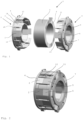
- Fig. 1 shows a schematic representation of a stator 1 for an electric motor comprising first stator segments 2 of a first half 3 of the stator 1, which are fixedly arranged relative to one another in a first cage 4, second stator segments 5 of a second half 6 of the stator 1, which are fixedly arranged relative to one another in a second cage 7, and a coil 8, which comprises a coil insulation 9, on which the coil 8 is wound.
- the first stator segments 2 of the first half 3 are connected to the second stator segments 5 of the second half 6 by a connecting means 10 in the form of a click connection comprising a first connecting part 10 and a second connecting part 11, wherein the first connecting part 10 is connected to the first cage 4 and the second connecting part 11 is connected to the second cage 7.
- Each of the first stator segments 2 has a first mechanical step-like connection 12, which is connected to a corresponding second mechanical step-like connection 13 of the corresponding second stator segment 5 by form fit.
- the step-like connections 12, 13 are arranged on an outer side 14 of the stator segments 2, 5 relative to an axis of symmetry of the stator 1.
- Inner sides 15 of the stator segments 2, 5 relative to the axis of symmetry of the stator 1 are arranged cylindrically next to each other in contact with each other.
- the stator segments 2, 5 with the outer sides 14 and the inner sides 15 serve as holders for the coil 8, which is positioned at a fixed position relative to the stator segments 2, 5 after connection.
- Fig. 2 shows a schematic representation of the stator 1 of Fig. 1 in an assembled state, wherein the first stator segments 2 are connected to the second stator segments 5 and the click connection comprising the first connecting part 10 and the second connecting part 11 holds the two halves of the stator 1 together.
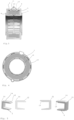
- Fig. 3 shows a sectional view of the assembled stator 1 of Fig. 2 , wherein the first step-like connection 12 of the first stator segment 2 is connected to the corresponding second step-like connection 13 of the second stator segment 5 in a connection region 20.
- the first stator segments 2 are mechanically connected to the first cage 4 and the second stator segments 5 are mechanically connected to the second cage 7 using connecting elements.
- the coil 8 is arranged at a fixed position between the stator segments 2, 5.
- Fig. 4 shows a top view of the assembled stator 1 from Fig. 2 , with the coil 8 arranged between the outer side 14 and the inner side 15 of the stator segments 2, 5.
- Fig. 5 shows a schematic representation in three-dimensional form and in a sectional view of the first stator segment 2 with the first step-like connection 12 on the outer side 14 and a first connecting element 30 for connecting the respective stator segment 2 to the first cage 4.
- the second stator segment 5 is shown in three-dimensional form and in a sectional view with the second step-like connection 13 on the outer side 14 and with a second connecting element 31 for connecting the respective stator segment 5 to the second cage 7.
Landscapes
- Engineering & Computer Science (AREA)
- Power Engineering (AREA)
- Iron Core Of Rotating Electric Machines (AREA)
Priority Applications (4)
| Application Number | Priority Date | Filing Date | Title |
|---|---|---|---|
| EP23216499.6A EP4572092A1 (fr) | 2023-12-14 | 2023-12-14 | Stator pour un moteur électrique |
| DE102024114992.2A DE102024114992A1 (de) | 2023-12-14 | 2024-05-28 | Linearverdichter |
| PCT/EP2024/082832 WO2025124852A1 (fr) | 2023-12-14 | 2024-11-19 | Compresseur linéaire |
| PCT/EP2024/085549 WO2025125254A1 (fr) | 2023-12-14 | 2024-12-10 | Stator pour moteur électrique |
Applications Claiming Priority (1)
| Application Number | Priority Date | Filing Date | Title |
|---|---|---|---|
| EP23216499.6A EP4572092A1 (fr) | 2023-12-14 | 2023-12-14 | Stator pour un moteur électrique |
Publications (1)
| Publication Number | Publication Date |
|---|---|
| EP4572092A1 true EP4572092A1 (fr) | 2025-06-18 |
Family
ID=89222478
Family Applications (1)
| Application Number | Title | Priority Date | Filing Date |
|---|---|---|---|
| EP23216499.6A Pending EP4572092A1 (fr) | 2023-12-14 | 2023-12-14 | Stator pour un moteur électrique |
Country Status (2)
| Country | Link |
|---|---|
| EP (1) | EP4572092A1 (fr) |
| WO (1) | WO2025125254A1 (fr) |
Citations (5)
| Publication number | Priority date | Publication date | Assignee | Title |
|---|---|---|---|---|
| KR100556974B1 (ko) * | 2004-04-29 | 2006-03-03 | 엘지전자 주식회사 | 리니어 모터용 고정자의 아우터 코어 조립 구조 및 그 방법 |
| US20060152092A1 (en) * | 2005-01-10 | 2006-07-13 | Lg Electronics Inc. | Stator for reciprocating motor and fabrication method thereof |
| US20060220473A1 (en) * | 2003-06-16 | 2006-10-05 | Kazuhiko Ueda | Linear motor and process for manufacturing the same, linear compressor, and stirling engine |
| JP5879975B2 (ja) * | 2011-11-30 | 2016-03-08 | いすゞ自動車株式会社 | 直動発電機 |
| EP2453556B1 (fr) | 2010-11-11 | 2023-05-03 | Grundfos Management a/s | Moteur électrique |
-
2023
- 2023-12-14 EP EP23216499.6A patent/EP4572092A1/fr active Pending
-
2024
- 2024-12-10 WO PCT/EP2024/085549 patent/WO2025125254A1/fr active Pending
Patent Citations (5)
| Publication number | Priority date | Publication date | Assignee | Title |
|---|---|---|---|---|
| US20060220473A1 (en) * | 2003-06-16 | 2006-10-05 | Kazuhiko Ueda | Linear motor and process for manufacturing the same, linear compressor, and stirling engine |
| KR100556974B1 (ko) * | 2004-04-29 | 2006-03-03 | 엘지전자 주식회사 | 리니어 모터용 고정자의 아우터 코어 조립 구조 및 그 방법 |
| US20060152092A1 (en) * | 2005-01-10 | 2006-07-13 | Lg Electronics Inc. | Stator for reciprocating motor and fabrication method thereof |
| EP2453556B1 (fr) | 2010-11-11 | 2023-05-03 | Grundfos Management a/s | Moteur électrique |
| JP5879975B2 (ja) * | 2011-11-30 | 2016-03-08 | いすゞ自動車株式会社 | 直動発電機 |
Also Published As
| Publication number | Publication date |
|---|---|
| WO2025125254A1 (fr) | 2025-06-19 |
Similar Documents
| Publication | Publication Date | Title |
|---|---|---|
| KR101006784B1 (ko) | 전기 기계용 다상 클로형 자극의 구조 | |
| JP6809476B2 (ja) | モータ | |
| JP4796048B2 (ja) | 商業的に低コストで高効率のモーター/発電機 | |
| US7737598B2 (en) | Electric motor having a stator | |
| CN100488006C (zh) | 直线电动机的线圈组合体及其制造方法 | |
| CN108370178B (zh) | 轴向间隙型旋转电机及其制造方法 | |
| US10944304B2 (en) | Motor and manufacturing method thereof | |
| US20220255386A1 (en) | Coil, stator, and motor | |
| JP2003533162A (ja) | 単極式横断磁束機械 | |
| JP2009189078A (ja) | 回転電機の固定子及び回転電機 | |
| WO2015079732A1 (fr) | Armature d'une machine électrique | |
| US10038348B2 (en) | Liner, stator assembly and associated method | |
| JP5097569B2 (ja) | コイルの製造方法および製造装置 | |
| JP2010239739A (ja) | 相間絶縁シート | |
| US20240063667A1 (en) | Stator with closed slots with a fluid injection cooling system for an electric machine and electric machine comprising said stator | |
| KR101247683B1 (ko) | 비정질 스테이터, 이를 이용한 전기 모터 및 그의 제조방법 | |
| EP4572092A1 (fr) | Stator pour un moteur électrique | |
| WO2005057755A1 (fr) | Machines polyphases a pole a griffes equipee d'un circuit magnetique segmente | |
| CN111316536A (zh) | 环形多相电机 | |
| JP4713219B2 (ja) | ステータの組立方法 | |
| US20210328485A1 (en) | A stator and a method for assembling a stator | |
| CN112913123B (zh) | 定子、电动机、压缩机、空调装置及定子的制造方法 | |
| US12308718B2 (en) | Molded coil, stator, and rotary electric machine | |
| US20220294283A1 (en) | Coil, stator, motor, and manufacturing method of stator | |
| EP3084929B1 (fr) | Stator pour une machine électrique |
Legal Events
| Date | Code | Title | Description |
|---|---|---|---|
| PUAI | Public reference made under article 153(3) epc to a published international application that has entered the european phase |
Free format text: ORIGINAL CODE: 0009012 |
|
| STAA | Information on the status of an ep patent application or granted ep patent |
Free format text: STATUS: THE APPLICATION HAS BEEN PUBLISHED |
|
| AK | Designated contracting states |
Kind code of ref document: A1 Designated state(s): AL AT BE BG CH CY CZ DE DK EE ES FI FR GB GR HR HU IE IS IT LI LT LU LV MC ME MK MT NL NO PL PT RO RS SE SI SK SM TR |
|
| STAA | Information on the status of an ep patent application or granted ep patent |
Free format text: STATUS: REQUEST FOR EXAMINATION WAS MADE |
|
| 17P | Request for examination filed |
Effective date: 20251218 |