EP4572095A1 - Rotor für eine elektrische rotierende maschine und elektrische rotierende maschine - Google Patents
Rotor für eine elektrische rotierende maschine und elektrische rotierende maschine Download PDFInfo
- Publication number
- EP4572095A1 EP4572095A1 EP24163316.3A EP24163316A EP4572095A1 EP 4572095 A1 EP4572095 A1 EP 4572095A1 EP 24163316 A EP24163316 A EP 24163316A EP 4572095 A1 EP4572095 A1 EP 4572095A1
- Authority
- EP
- European Patent Office
- Prior art keywords
- rotor
- straight
- slots
- segments
- package
- Prior art date
- Legal status (The legal status is an assumption and is not a legal conclusion. Google has not performed a legal analysis and makes no representation as to the accuracy of the status listed.)
- Pending
Links
Images

Classifications
-
- H—ELECTRICITY
- H02—GENERATION; CONVERSION OR DISTRIBUTION OF ELECTRIC POWER
- H02K—DYNAMO-ELECTRIC MACHINES
- H02K1/00—Details of the magnetic circuit
- H02K1/06—Details of the magnetic circuit characterised by the shape, form or construction
- H02K1/22—Rotating parts of the magnetic circuit
- H02K1/27—Rotor cores with permanent magnets
- H02K1/2706—Inner rotors
- H02K1/272—Inner rotors the magnetisation axis of the magnets being perpendicular to the rotor axis
- H02K1/274—Inner rotors the magnetisation axis of the magnets being perpendicular to the rotor axis the rotor consisting of two or more circumferentially positioned magnets
- H02K1/2753—Inner rotors the magnetisation axis of the magnets being perpendicular to the rotor axis the rotor consisting of two or more circumferentially positioned magnets the rotor consisting of magnets or groups of magnets arranged with alternating polarity
- H02K1/276—Magnets embedded in the magnetic core, e.g. interior permanent magnets [IPM]
- H02K1/2766—Magnets embedded in the magnetic core, e.g. interior permanent magnets [IPM] having a flux concentration effect
-
- H—ELECTRICITY
- H02—GENERATION; CONVERSION OR DISTRIBUTION OF ELECTRIC POWER
- H02K—DYNAMO-ELECTRIC MACHINES
- H02K1/00—Details of the magnetic circuit
- H02K1/06—Details of the magnetic circuit characterised by the shape, form or construction
- H02K1/22—Rotating parts of the magnetic circuit
- H02K1/27—Rotor cores with permanent magnets
- H02K1/2706—Inner rotors
- H02K1/272—Inner rotors the magnetisation axis of the magnets being perpendicular to the rotor axis
- H02K1/274—Inner rotors the magnetisation axis of the magnets being perpendicular to the rotor axis the rotor consisting of two or more circumferentially positioned magnets
- H02K1/2753—Inner rotors the magnetisation axis of the magnets being perpendicular to the rotor axis the rotor consisting of two or more circumferentially positioned magnets the rotor consisting of magnets or groups of magnets arranged with alternating polarity
- H02K1/276—Magnets embedded in the magnetic core, e.g. interior permanent magnets [IPM]
-
- H—ELECTRICITY
- H02—GENERATION; CONVERSION OR DISTRIBUTION OF ELECTRIC POWER
- H02K—DYNAMO-ELECTRIC MACHINES
- H02K2213/00—Specific aspects, not otherwise provided for and not covered by codes H02K2201/00 - H02K2211/00
- H02K2213/03—Machines characterised by numerical values, ranges, mathematical expressions or similar information
Definitions
- the present invention relates to the field of rotating electrical machines and, more particularly, to reluctance machines, reluctance machines assisted by permanent magnets and permanent magnet machines.
- Electrical machines are equipment used to transform electrical energy into mechanical energy, in the case of engines, and vice versa, in the case of generators. They are generally formed by a rotor, which is the rotating energized component, a static element called stator, equally energized, bearings responsible for connecting the static and rotating parts, and the housing that constitutes not only the role of enclosure of the systems already mentioned, but promotes integration with other auxiliary systems.
- the rotor In the case of reluctance machines, with pure reluctance or being assisted by permanent magnets, the rotor is specifically designed to maximize the variation of magnetic reluctance when the motor is in operation, and when the reluctance machine is assisted by permanent magnets , the use of a permanent magnet assists in the magnetic flux, thus obtaining higher levels of efficiency and making it possible to reduce the size of the housing.
- the rotor In the case of permanent magnet machines, the rotor has permanent magnets to produce excitation.
- the use of permanent magnets reduces Joule losses in the rotor, thus obtaining higher levels of efficiency and making it possible to reduce the size of the housing and increase the useful life of the machine.
- torque ripple A potential problem associated with reluctance machines, permanent magnet assisted reluctance machines and permanent magnet machines is so-called torque ripple. This is a fluctuation in the output torque of the energized machine, which influences the operational stability and reliability of the machine.
- each set of slots comprises: a first radially outermost slot having a substantially U-shape with a central straight segment and two opposing straight lateral segments, wherein each of the opposing lateral segments makes an obtuse angle ⁇ with the central segment and comprises an end wherein opposing curved grooves are formed and wherein each of the opposing curved grooves of each opposing lateral straight segment forms a radius R1 centered at a point collinear with a straight edge of such opposing lateral straight segment; and second and third radially innermost slots, each of the second and third slots comprising a first and a second straight segments making an obtuse angle ⁇ to each other, wherein the second straight segment of each of the second and third slots comprises an end wherein opposing curved
- the two opposing lateral straight segments of the first slot are mirrored segments and the second and third radially innermost slots are mirrored to each other.
- the rotor package comprises, in an embodiment of the invention, four sets of slots equally spaced apart.
- the obtuse angle ⁇ is greater than 90° and less than 180°. Even more preferably, the angle ⁇ is 90° + (180° / number of poles).
- the obtuse angle ⁇ is greater than 90° and less than 180°. Even more preferably, the angle ⁇ is 90° + (180° / number of poles).
- the radius R1 is preferably in the range between 0.4 mm and 25 mm and the radius R2 is preferably in the range between 0.4 mm and 22 mm.
- the first slot is positioned in the rotor package so that an extreme straight portion of the ends of the mirrored opposing straight lateral segments is spaced from a circular outer edge of the rotor package by a maximum distance D1 and a minimum distance D2.
- the maximum distance D1 is in the range between 0.5 mm and 15 mm and the minimum distance D2 is in the range between 0.25 mm and 15 mm.
- the second slot is positioned in the rotor package so that an extreme straight portion of its second straight segment is spaced from a circular outer edge of the rotor package by a maximum distance A1 and a minimum distance A2; and the third slot is positioned in the rotor package so that an extreme straight portion of its second straight segment is spaced from a circular outer edge of the rotor package by the maximum distance A1 and the minimum distance A2.
- the maximum distance A1 is in the range between 0.5 mm and 15 mm and the minimum distance A2 is in the range between 0.25 mm and 15 mm.
- the first straight segments of the second and third slots are parallel to the central segment of the first slot and spaced therefrom by a distance E.
- the distance E is preferably in the range between 1 mm and 30 mm.
- each of the first straight segments of the second and third slots is spaced from a circular edge of a central hole of the rotor package by a minimum distance F.
- the minimum distance F is preferably in the range between 4 mm and 200 mm.
- at least one end of the slots of the slot package is a straight end with curved corners.
- the present invention further relates to a rotating permanent magnet electrical machine comprising a stator and a rotor in accordance with the present invention.
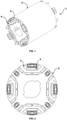
- Figure 1 shows a rotor 1 of a rotating permanent magnet electrical machine, whether it is a motor or a generator, with the shaft on which it is mounted removed.
- the rotor 1 comprises a sheet package or rotor package 2, with a plurality of sets of slots 3 into which permanent magnets 4 are inserted.
- the construction and function of this type of rotor with internal permanent magnets is known to those skilled in the art, so they will be detailed in this description, but only the elements and characteristics necessary for a person skilled in the art to fully understand the invention.
- the rotor package 2 has a substantially cylindrical shape, defining an outer circular edge, and comprises four sets of slots distributed close to the outer periphery of the package.
- FIG. 3 shows the rotor package 2 without the magnets.
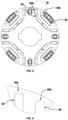
- each of the sets of slots comprises at least one first radially outermost slot 5 and two radially innermost slots 6, 7. Additional slots may be provided, as soon as they follow the shape of the slots 5 or 6, 7.
- the first slot 5 comprises a substantially U-shape with three straight segments: a central segment 5a and two mirror-opposing lateral segments 5b, 5c that each make an obtuse angle ⁇ with the central segment 5a.
- Each of the mirror-opposing lateral segments 5b, 5c comprises an end at which curved grooves 5d, 5e are formed.
- the obtuse angle ⁇ is greater than 90° and less than 180°, being defined as a function of the polarity of the electric motor.
- angle ⁇ is given by the formula 90° + (180° / n), where n is the number of poles of the motor.
- angle ⁇ could assume the values in the following table: Table I - Examples of angle ⁇ Number of poles Preferred angle (°) 4 180 6 135 8 120 10 112,5 12 108 14 105 16 102,86 18 100 20 99
- each of the curved grooves 5d, 5e forms a radius R1 centered at a point collinear with the straight edge 5f of the lateral segment 5b.
- the first slot 5 is positioned in the package 2 so that a straight edge portion 5g of the ends of the lateral segments 5b, 5c of the slots is spaced from the outer edge of the package 2 by a maximum distance D1 and a minimum distance D2, considering the circular profile of the edge.
- the radius R1 is in the range between 0.4 mm and 25 mm, the maximum distance D1 is in the range between 0.5 mm and 15 mm and the minimum distance D2 is in the range between 0 .25mm and 15mm. Even more preferably, the radius R1 is less than 2 mm, the maximum distance D1 is 5 mm and the minimum distance D2 is between 0.25 and 5 mm.
- the two lateral segments 5b, 5c are preferably mirrored, so that the same radius R1 and distances D1, D2 shown in figure 4 in relation to the lateral segment 5b are found in a mirrored way in the lateral segment 5c. It should be understood, however, that in alternative embodiments, there could be an asymmetry between the lateral segments 5b and 5c, with distances D1 and D2, and radius R1 and R2 within the ranges described.
- the radially innermost slots, second and third slots 6, 7, have, taken together, a similar shape to the first slot 5, except for the fact that they are non-contiguous, that is, they are divided and separated by a portion of package 2a.
- Slot 6 comprises two straight segments 6a, 6b that make an obtuse angle ⁇ between them.
- the angle ⁇ is greater than 90° and less than 180°, being defined as a function of the polarity of the electric motor.
- angle ⁇ is given by the formula 90° + (180° / n), where n is the number of poles of the motor.
- angle ⁇ could assume the values in the following table: Table II - Examples of angle ⁇ Number of poles Preferred angle (°) 4 180 6 135 8 120 10 112,5 12 108 14 105 16 102,86 18 100 20 99
- angles ⁇ and ⁇ are equal, so that there is no narrowing in the reluctance path.
- such angles could be different.
- the first straight segment 6a of the second slot 6 is parallel to the central segment 5a of the first slot 5 and spaced therefrom by a distance E.
- the distance E is in range between 1 mm and 30 mm.
- the second straight segment 6b of the second slot 6 comprises an end at which curved grooves 6d, 6e are formed (see figure 4 ).
- Each of the curved grooves 6d, 6e forms a radius R2 centered at a point collinear with the straight edge 6f of the lateral segment 6b.
- the second slot 6 is positioned in the package 2 so that a straight edge portion 6g of the second straight segment 6b is spaced from the outer edge of the package 2 by a maximum distance A1 and a minimum distance A2, considering the circular profile of the edge.
- the radius R2 is in the range between 0.4 mm and 22 mm, the maximum distance A1 is in the range between 0.5 mm and 15 mm and the minimum distance A2 is in the range between 0.25 mm and 15 mm. Even more preferably, the radius R2 is less than 2 mm, the maximum distance A1 is 5 mm and the minimum distance A2 is between 0.25 and 5 mm.
- the first straight segment 6a of the second slot is away from the circular edge of the central hole 2b of the rotor package 2 by a minimum distance F.
- the distance F is in the range between 4 mm and 200 mm.
- the third slot 7 has a mirrored shape in relation to the second slot 6, with a first and second straight segments 7a, 7b with the angle ⁇ between them, and with the curved grooves formed at the end of the second segment 7b. It should be understood, however, that such mirroring might not be present in alternative embodiments of the invention.
- Figures 5 and 6 show an alternative embodiment of the invention, in which at least one of the ends 50b and 60b of the slots 50 and 60 is a straight end with curved corners.
- the two ends of the slots 50 and 60 are straight ends with curved corners and the other shape characteristics are similar to the embodiment of figures 1 to 4 . It should be noted, however, that in embodiments of the invention, the slots could have a straight end with curved corners and the other end with a shape similar to the ends with curved grooves of figures 1 to 4 .
- the plurality of sets of slots 3 of the sheet package or rotor package 2 may have both a set of slots 3 like the sets of the embodiment of figures 1 to 4 and a set of slots 3 like the sets of the embodiment of figures 5 and 6 .
Landscapes
- Engineering & Computer Science (AREA)
- Power Engineering (AREA)
- Permanent Field Magnets Of Synchronous Machinery (AREA)
- Iron Core Of Rotating Electric Machines (AREA)
Applications Claiming Priority (1)
| Application Number | Priority Date | Filing Date | Title |
|---|---|---|---|
| BR102023026162-0A BR102023026162A2 (pt) | 2023-12-12 | Rotor para uma máquina elétrica girante e máquina elétrica girante |
Publications (1)
| Publication Number | Publication Date |
|---|---|
| EP4572095A1 true EP4572095A1 (de) | 2025-06-18 |
Family
ID=90365092
Family Applications (1)
| Application Number | Title | Priority Date | Filing Date |
|---|---|---|---|
| EP24163316.3A Pending EP4572095A1 (de) | 2023-12-12 | 2024-03-13 | Rotor für eine elektrische rotierende maschine und elektrische rotierende maschine |
Country Status (4)
| Country | Link |
|---|---|
| US (1) | US20250192627A1 (de) |
| EP (1) | EP4572095A1 (de) |
| CN (1) | CN120150400A (de) |
| MX (1) | MX2024003348A (de) |
Citations (4)
| Publication number | Priority date | Publication date | Assignee | Title |
|---|---|---|---|---|
| US20190181703A1 (en) * | 2017-12-13 | 2019-06-13 | Baumueller Nuernberg Gmbh | Electrical machine |
| US20200259377A1 (en) * | 2019-02-12 | 2020-08-13 | Toyota Jidosha Kabushiki Kaisha | Rotary electric machine |
| US20200395799A1 (en) * | 2018-05-08 | 2020-12-17 | Gree Electric Appliances, Inc. Of Zhuhai | Rotor Structure, Permanent Magnet Assisted Synchronous Reluctance Motor and Electric Car |
| US11799333B2 (en) * | 2018-03-16 | 2023-10-24 | Gree Electric Appliances, Inc. Of Zhuhai | Permanent magnet auxiliary synchronous reluctance motor and electric vehicle provided with same |
Family Cites Families (34)
| Publication number | Priority date | Publication date | Assignee | Title |
|---|---|---|---|---|
| US2913607A (en) * | 1957-01-16 | 1959-11-17 | Allis Louis Co | Synchronous induction motor |
| JP3818340B2 (ja) * | 1997-09-26 | 2006-09-06 | 株式会社富士通ゼネラル | 永久磁石電動機 |
| JP2000050542A (ja) * | 1998-07-23 | 2000-02-18 | Okuma Corp | リラクタンスモータ |
| DE19933009A1 (de) * | 1998-07-24 | 2000-02-10 | Matsushita Electric Industrial Co Ltd | Motor mit interne Permanentmagneten enthaltendem Rotor und einen solchen Motor verwendende Antriebseinheit |
| US7489062B2 (en) * | 2005-11-14 | 2009-02-10 | General Electric Company | Synchronous reluctance machine with a novel rotor topology |
| US20070152527A1 (en) * | 2005-12-23 | 2007-07-05 | Okuma Corporation | Reluctance motor |
| KR101021120B1 (ko) * | 2009-07-14 | 2011-03-14 | 한양대학교 산학협력단 | 고속모터용 회전자 |
| DE102009050991A1 (de) * | 2009-10-28 | 2011-05-05 | Bayerische Motoren Werke Aktiengesellschaft | Elektrische Antriebsmaschine für ein Fahrzeug |
| CN102986123A (zh) * | 2010-07-02 | 2013-03-20 | Abb研究有限公司 | 具有轮辐开口的转子盘 |
| JP5480176B2 (ja) * | 2011-02-03 | 2014-04-23 | アイシン・エィ・ダブリュ株式会社 | 回転電機用回転子 |
| US8860275B2 (en) * | 2011-12-09 | 2014-10-14 | GM Global Technology Operations LLC | Multi-layer arc-shaped permanent magnet machine with reduced rotational stress |
| US9472986B2 (en) * | 2011-12-26 | 2016-10-18 | Mitsubishi Electric Corporation | Rotor |
| DE102013201353A1 (de) * | 2012-02-10 | 2013-08-14 | Ksb Aktiengesellschaft | Rotor und Reluktanzmotor |
| FR2987184B1 (fr) * | 2012-02-20 | 2016-07-29 | Moteurs Leroy-Somer | Rotor de machine electrique tournante a concentration de flux. |
| JP5948127B2 (ja) * | 2012-04-23 | 2016-07-06 | 日立オートモティブシステムズ株式会社 | 永久磁石回転電機及びそれを用いた電動車両 |
| US8664823B2 (en) * | 2012-05-30 | 2014-03-04 | GM Global Technology Operations LLC | Magnetic barrier for minimizing demagnetization in bi-permanent magnet synchronous machines |
| CN105745820B (zh) * | 2013-11-20 | 2018-11-16 | 日立汽车系统株式会社 | 旋转电机和具备该旋转电机的电动车辆 |
| JP6215041B2 (ja) * | 2013-12-20 | 2017-10-18 | U−Mhiプラテック株式会社 | モータ |
| JP6147661B2 (ja) * | 2013-12-27 | 2017-06-14 | 日立オートモティブシステムズ株式会社 | 回転子、およびこれを備えた永久磁石式回転電機、電動駆動システム、電動車両 |
| JP2015159706A (ja) * | 2014-01-22 | 2015-09-03 | 日本精工株式会社 | 電動機、電動パワーステアリング装置及び車両 |
| ITUB20150608A1 (it) * | 2015-04-14 | 2016-10-14 | Ge Avio Srl | Metodo di realizzazione di una struttura di rotore di una macchina elettrica sincrona a riluttanza, e relativa macchina elettrica sincrona a riluttanza |
| WO2017154156A1 (ja) * | 2016-03-09 | 2017-09-14 | 三菱重工業株式会社 | 突極型回転子、および、回転子の製造方法 |
| US10439456B2 (en) * | 2016-04-25 | 2019-10-08 | General Electric Company | Sleeve rotor synchronous reluctance electric machine |
| US10211690B2 (en) * | 2016-04-28 | 2019-02-19 | Faraday & Future Inc. | IPM machine with specialized rotor for automotive electric vehicles |
| JP6571050B2 (ja) * | 2016-06-29 | 2019-09-04 | 株式会社東芝 | 同期リラクタンス型回転電機 |
| JP6709712B2 (ja) * | 2016-10-07 | 2020-06-17 | 東芝産業機器システム株式会社 | 同期リラクタンス型回転電機 |
| US10715017B2 (en) * | 2017-06-02 | 2020-07-14 | Hamilton Sundstrand Corporation | Hybrid synchronous machines |
| CN108023421B (zh) * | 2017-12-21 | 2024-05-28 | 珠海格力电器股份有限公司 | 电机转子和永磁电机 |
| CN111725918B (zh) * | 2018-03-16 | 2021-07-27 | 珠海格力节能环保制冷技术研究中心有限公司 | 转子结构、永磁辅助同步磁阻电机 |
| CN108336842B (zh) * | 2018-03-16 | 2020-10-16 | 珠海格力节能环保制冷技术研究中心有限公司 | 转子结构、永磁辅助同步磁阻电机及电动汽车 |
| CN110149015B (zh) * | 2019-06-19 | 2025-05-16 | 珠海格力电器股份有限公司 | 直接起动同步磁阻电机转子结构、电机 |
| JP7415871B2 (ja) * | 2020-10-22 | 2024-01-17 | トヨタ自動車株式会社 | 回転電機 |
| JP7478104B2 (ja) * | 2021-01-08 | 2024-05-02 | 株式会社アイシン | ロータコア |
| US11955843B2 (en) * | 2021-12-22 | 2024-04-09 | Abb Schweiz Ag | Synchronous reluctance motor |
-
2024
- 2024-03-13 EP EP24163316.3A patent/EP4572095A1/de active Pending
- 2024-03-15 MX MX2024003348A patent/MX2024003348A/es unknown
- 2024-03-27 US US18/618,886 patent/US20250192627A1/en active Pending
- 2024-04-10 CN CN202410428884.4A patent/CN120150400A/zh active Pending
Patent Citations (4)
| Publication number | Priority date | Publication date | Assignee | Title |
|---|---|---|---|---|
| US20190181703A1 (en) * | 2017-12-13 | 2019-06-13 | Baumueller Nuernberg Gmbh | Electrical machine |
| US11799333B2 (en) * | 2018-03-16 | 2023-10-24 | Gree Electric Appliances, Inc. Of Zhuhai | Permanent magnet auxiliary synchronous reluctance motor and electric vehicle provided with same |
| US20200395799A1 (en) * | 2018-05-08 | 2020-12-17 | Gree Electric Appliances, Inc. Of Zhuhai | Rotor Structure, Permanent Magnet Assisted Synchronous Reluctance Motor and Electric Car |
| US20200259377A1 (en) * | 2019-02-12 | 2020-08-13 | Toyota Jidosha Kabushiki Kaisha | Rotary electric machine |
Also Published As
| Publication number | Publication date |
|---|---|
| MX2024003348A (es) | 2025-07-01 |
| US20250192627A1 (en) | 2025-06-12 |
| CN120150400A (zh) | 2025-06-13 |
Similar Documents
| Publication | Publication Date | Title |
|---|---|---|
| US7012350B2 (en) | Segmented stator switched reluctance machine | |
| US10447102B2 (en) | Permanent magnet electrical machines and methods of assembling the same | |
| JP4838348B2 (ja) | 永久磁石型モータ及び密閉型圧縮機及びファンモータ | |
| EP4084293A2 (de) | Elektrische axialflussmaschine und korrespondierendes verfahren zur montage | |
| US6700284B2 (en) | Fan assembly including a segmented stator switched reluctance fan motor | |
| US20010048264A1 (en) | Brushless DC motor having reduced cogging torque | |
| US9667106B2 (en) | Motor housing and methods of assembling the same | |
| US20200403487A1 (en) | Motor, electric blower, electric vacuum cleaner, and hand dryer | |
| CN103026584A (zh) | 电机的用于减少涡流的绕组齿和组件 | |
| EP3748818A1 (de) | Rotor und motor damit | |
| US7109630B2 (en) | Electric rotating machine and manufacturing process thereof | |
| US20250192627A1 (en) | Rotor for a rotating electric machine and rotating electric machine | |
| EP1564872A2 (de) | Magnetkreise für elektrische Maschinen | |
| EP2922177A1 (de) | Statorsegment mit asymmetrischer Halbzahnform für große Generatoren | |
| JP6108655B2 (ja) | 発電機用磁石 | |
| WO2021224069A1 (en) | Permanent magnet machine | |
| CN120693465A (zh) | 径向磁轴承、压缩机以及制冷机 | |
| WO2001003271A1 (en) | Electric motor rotor | |
| US11050332B2 (en) | Enhanced permanent magnet claw pole segment geometry | |
| CN114069908A (zh) | 定子、电机、压缩机和电器设备 | |
| BR102023026162A2 (pt) | Rotor para uma máquina elétrica girante e máquina elétrica girante | |
| CN114142633A (zh) | 定子、电机、压缩机和制冷设备 | |
| KR102764518B1 (ko) | 토크 리플 저감 회전자 | |
| CN114337023A (zh) | 旋转电机 | |
| CN117652081A (zh) | 磁波动齿轮装置 |
Legal Events
| Date | Code | Title | Description |
|---|---|---|---|
| PUAI | Public reference made under article 153(3) epc to a published international application that has entered the european phase |
Free format text: ORIGINAL CODE: 0009012 |
|
| STAA | Information on the status of an ep patent application or granted ep patent |
Free format text: STATUS: THE APPLICATION HAS BEEN PUBLISHED |
|
| AK | Designated contracting states |
Kind code of ref document: A1 Designated state(s): AL AT BE BG CH CY CZ DE DK EE ES FI FR GB GR HR HU IE IS IT LI LT LU LV MC ME MK MT NL NO PL PT RO RS SE SI SK SM TR |
|
| STAA | Information on the status of an ep patent application or granted ep patent |
Free format text: STATUS: REQUEST FOR EXAMINATION WAS MADE |
|
| 17P | Request for examination filed |
Effective date: 20251218 |