EP4572128A1 - Dispositif d'entraînement pour moteur synchrone à aimant permanent, et dispositif de commande - Google Patents
Dispositif d'entraînement pour moteur synchrone à aimant permanent, et dispositif de commande Download PDFInfo
- Publication number
- EP4572128A1 EP4572128A1 EP23852468.0A EP23852468A EP4572128A1 EP 4572128 A1 EP4572128 A1 EP 4572128A1 EP 23852468 A EP23852468 A EP 23852468A EP 4572128 A1 EP4572128 A1 EP 4572128A1
- Authority
- EP
- European Patent Office
- Prior art keywords
- permanent magnet
- synchronous motor
- magnet synchronous
- alternating current
- rotor
- Prior art date
- Legal status (The legal status is an assumption and is not a legal conclusion. Google has not performed a legal analysis and makes no representation as to the accuracy of the status listed.)
- Pending
Links
Images







Classifications
-
- H—ELECTRICITY
- H02—GENERATION; CONVERSION OR DISTRIBUTION OF ELECTRIC POWER
- H02P—CONTROL OR REGULATION OF ELECTRIC MOTORS, ELECTRIC GENERATORS OR DYNAMO-ELECTRIC CONVERTERS; CONTROLLING TRANSFORMERS, REACTORS OR CHOKE COILS
- H02P21/00—Arrangements or methods for the control of electric machines by vector control, e.g. by control of field orientation
- H02P21/24—Vector control not involving the use of rotor position or rotor speed sensors
- H02P21/26—Rotor flux based control
-
- H—ELECTRICITY
- H02—GENERATION; CONVERSION OR DISTRIBUTION OF ELECTRIC POWER
- H02P—CONTROL OR REGULATION OF ELECTRIC MOTORS, ELECTRIC GENERATORS OR DYNAMO-ELECTRIC CONVERTERS; CONTROLLING TRANSFORMERS, REACTORS OR CHOKE COILS
- H02P21/00—Arrangements or methods for the control of electric machines by vector control, e.g. by control of field orientation
- H02P21/22—Current control, e.g. using a current control loop
-
- H—ELECTRICITY
- H02—GENERATION; CONVERSION OR DISTRIBUTION OF ELECTRIC POWER
- H02P—CONTROL OR REGULATION OF ELECTRIC MOTORS, ELECTRIC GENERATORS OR DYNAMO-ELECTRIC CONVERTERS; CONTROLLING TRANSFORMERS, REACTORS OR CHOKE COILS
- H02P21/00—Arrangements or methods for the control of electric machines by vector control, e.g. by control of field orientation
- H02P21/14—Estimation or adaptation of machine parameters, e.g. flux, current or voltage
-
- H—ELECTRICITY
- H02—GENERATION; CONVERSION OR DISTRIBUTION OF ELECTRIC POWER
- H02P—CONTROL OR REGULATION OF ELECTRIC MOTORS, ELECTRIC GENERATORS OR DYNAMO-ELECTRIC CONVERTERS; CONTROLLING TRANSFORMERS, REACTORS OR CHOKE COILS
- H02P21/00—Arrangements or methods for the control of electric machines by vector control, e.g. by control of field orientation
- H02P21/14—Estimation or adaptation of machine parameters, e.g. flux, current or voltage
- H02P21/18—Estimation of position or speed
-
- H—ELECTRICITY
- H02—GENERATION; CONVERSION OR DISTRIBUTION OF ELECTRIC POWER
- H02P—CONTROL OR REGULATION OF ELECTRIC MOTORS, ELECTRIC GENERATORS OR DYNAMO-ELECTRIC CONVERTERS; CONTROLLING TRANSFORMERS, REACTORS OR CHOKE COILS
- H02P21/00—Arrangements or methods for the control of electric machines by vector control, e.g. by control of field orientation
- H02P21/24—Vector control not involving the use of rotor position or rotor speed sensors
-
- H—ELECTRICITY
- H02—GENERATION; CONVERSION OR DISTRIBUTION OF ELECTRIC POWER
- H02P—CONTROL OR REGULATION OF ELECTRIC MOTORS, ELECTRIC GENERATORS OR DYNAMO-ELECTRIC CONVERTERS; CONTROLLING TRANSFORMERS, REACTORS OR CHOKE COILS
- H02P6/00—Arrangements for controlling synchronous motors or other dynamo-electric motors using electronic commutation dependent on the rotor position; Electronic commutators therefor
- H02P6/14—Electronic commutators
- H02P6/16—Circuit arrangements for detecting position
-
- H—ELECTRICITY
- H02—GENERATION; CONVERSION OR DISTRIBUTION OF ELECTRIC POWER
- H02P—CONTROL OR REGULATION OF ELECTRIC MOTORS, ELECTRIC GENERATORS OR DYNAMO-ELECTRIC CONVERTERS; CONTROLLING TRANSFORMERS, REACTORS OR CHOKE COILS
- H02P6/00—Arrangements for controlling synchronous motors or other dynamo-electric motors using electronic commutation dependent on the rotor position; Electronic commutators therefor
- H02P6/14—Electronic commutators
- H02P6/16—Circuit arrangements for detecting position
- H02P6/18—Circuit arrangements for detecting position without separate position detecting elements
-
- H—ELECTRICITY
- H02—GENERATION; CONVERSION OR DISTRIBUTION OF ELECTRIC POWER
- H02P—CONTROL OR REGULATION OF ELECTRIC MOTORS, ELECTRIC GENERATORS OR DYNAMO-ELECTRIC CONVERTERS; CONTROLLING TRANSFORMERS, REACTORS OR CHOKE COILS
- H02P6/00—Arrangements for controlling synchronous motors or other dynamo-electric motors using electronic commutation dependent on the rotor position; Electronic commutators therefor
- H02P6/14—Electronic commutators
- H02P6/16—Circuit arrangements for detecting position
- H02P6/18—Circuit arrangements for detecting position without separate position detecting elements
- H02P6/183—Circuit arrangements for detecting position without separate position detecting elements using an injected high frequency signal
-
- H—ELECTRICITY
- H02—GENERATION; CONVERSION OR DISTRIBUTION OF ELECTRIC POWER
- H02P—CONTROL OR REGULATION OF ELECTRIC MOTORS, ELECTRIC GENERATORS OR DYNAMO-ELECTRIC CONVERTERS; CONTROLLING TRANSFORMERS, REACTORS OR CHOKE COILS
- H02P6/00—Arrangements for controlling synchronous motors or other dynamo-electric motors using electronic commutation dependent on the rotor position; Electronic commutators therefor
- H02P6/14—Electronic commutators
- H02P6/16—Circuit arrangements for detecting position
- H02P6/18—Circuit arrangements for detecting position without separate position detecting elements
- H02P6/185—Circuit arrangements for detecting position without separate position detecting elements using inductance sensing, e.g. pulse excitation
-
- H—ELECTRICITY
- H02—GENERATION; CONVERSION OR DISTRIBUTION OF ELECTRIC POWER
- H02P—CONTROL OR REGULATION OF ELECTRIC MOTORS, ELECTRIC GENERATORS OR DYNAMO-ELECTRIC CONVERTERS; CONTROLLING TRANSFORMERS, REACTORS OR CHOKE COILS
- H02P6/00—Arrangements for controlling synchronous motors or other dynamo-electric motors using electronic commutation dependent on the rotor position; Electronic commutators therefor
- H02P6/28—Arrangements for controlling current
-
- H—ELECTRICITY
- H02—GENERATION; CONVERSION OR DISTRIBUTION OF ELECTRIC POWER
- H02P—CONTROL OR REGULATION OF ELECTRIC MOTORS, ELECTRIC GENERATORS OR DYNAMO-ELECTRIC CONVERTERS; CONTROLLING TRANSFORMERS, REACTORS OR CHOKE COILS
- H02P2207/00—Indexing scheme relating to controlling arrangements characterised by the type of motor
- H02P2207/05—Synchronous machines, e.g. with permanent magnets or DC excitation
Definitions
- the present invention relates to a driving device for a permanent magnet synchronous motor and a control method.
- a permanent magnet synchronous motor (hereinafter referred to as a PM motor) is widely used in industry, home appliances, medical equipment, electric vehicles, railways, and the like.
- PM motor since the PM motor needs to control a current phase for rotation driving based on the position angle of a rotor, it is necessary to use a configuration in which a position sensor is provided for the rotor.
- position sensorless control that does not directly detect the rotor position has also been practically used.
- Most position sensorless controls use an induced voltage generated internally when the PM motor is rotated.
- position sensorless control using a saliency structure of the rotor has been considered and has already been practically used. Due to implementation of the position sensorless control, it is not necessary to use a precise position sensor, thereby making it possible to drive a motor in harsh environments.
- the position sensor is eliminated, it is possible not only to achieve miniaturization of the whole device, but also to avoid the risk of sensor failure.
- Patent Literature 1 describes a position sensorless method using magnetic saliency of a rotor of a PM motor.
- a harmonic voltage for estimating the rotor position is continuously applied to an estimated phase axis of the rotor, an error between the estimated position and an actual rotor phase is calculated from a harmonic current generated on an axis perpendicular to the estimated phase axis, and the error is corrected to implement sensorless driving.
- Patent Literature 2 magnetic saliency of a rotor of a PM motor is used, and a pulse voltage generated by an inverter is used as a harmonic voltage for estimating the position of the rotor.
- Patent Literature 3 magnetic saliency of a rotor of a PM motor is used, and a current change rate generated by applied harmonics is used to perform position estimation of the rotor.
- Patent Literature 1 Patent Literature 2, and Patent Literature 3
- magnetic saliency is required in the rotor, and generally, there is a problem in that the methods can be applied only to a rotor having a embedded magnet structure and configured to provide prominent magnetic saliency.
- many small and inexpensive PM motors have surface magnet structures in which inexpensive magnets are attached to the rotor surface, and in such a case, since there is almost no magnetic saliency, sensorless driving of the methods described in Patent Literature 1, Patent Literature 2, and Patent Literature 3 cannot be applied.
- Patent Literature 2 harmonics generated by a switching operation of an inverter are used as harmonics for position estimation.
- the harmonics generated by the inverter change significantly depending on the phase and modulation rate of a voltage output by the inverter, and cannot be uniquely determined. Therefore, as described in Patent Literature 1 and Patent Literature 3, it becomes difficult to perform position estimation of the rotor due to the influence of the magnetic circuit on the stator side depending on the conditions.
- Patent Literature 1 Patent Literature 2, and Patent Literature 3
- position sensorless control cannot be performed.
- the methods cannot be used for position estimation in the low-speed range, and in such cases, it is required to prepare a separate position sensor.
- an object of the present invention is to implement position sensorless control in a PM motor, in which the position sensorless control enables position estimation in a low-speed range as well regardless of a structure related to rotor saliency.
- a driving device for a permanent magnet synchronous motor includes:
- a control method for a permanent magnet synchronous motor including an inverter configured to drive the permanent magnet synchronous motor and a detection unit configured to detect a current flowing through the permanent magnet synchronous motor, includes controlling the permanent magnet synchronous motor via the inverter using a current value detected by the detection unit, and
- FIG. 1A illustrates the configuration of the PM motor 100 according to the present embodiment.
- the PM motor 100 includes a rotor 101 and a stator 102.
- the stator 102 has a concentrated winding configuration in which a coil formed of copper wire or the like is wound around a stator core including a salient pole.
- a coil formed of copper wire or the like is wound around a stator core including a salient pole.
- an example in which the stator 102 includes six stator cores is illustrated, but the number of stator cores is not limited thereto.
- the coil is not limited to the concentrated winding configuration, and may be a distributed winding configuration.
- the rotor 101 includes a permanent magnet.
- Examples of the rotor 101 include a surface magnet rotor in which a permanent magnet is attached to the surface around a rotor core, as illustrated in Fig. 1B , and an embedded magnet rotor in which a permanent magnet is embedded in a rotor core, as illustrated in Fig. 1C .
- the example in Figs. 1A to 1C illustrates an example of a four-pole rotor.
- a permanent magnet is only present on the d axis, so the inductance in the q-axis direction is large (Ld ⁇ Lq), thereby having saliency.
- a rotor structure causes a difference in inductance between the d axis and the q axis.
- the method according to the present embodiment illustrates a configuration that can be applied to the configuration of the surface magnet rotor having weak saliency (weak salient pole), as illustrated in Fig. 1B .
- weak saliency weak salient pole
- non-saliency (weak salient pole) in the surface magnet rotor is described as being extremely small compared to the saliency of the configuration of the embedded magnet rotor. Details will be described later.
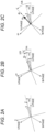
- Figs. 2A to 2C are diagrams illustrating a difference between a rotor position estimation method of the related art described in Patent Literature 1 and a rotor position estimation method according to the present embodiment.
- Fig. 2A illustrates axes of a U-phase, a V-phase, and a W-phase of a three-phase AC motor serving as a PM motor.
- the d axis indicates a direction of magnet magnetic flux ⁇ .
- ⁇ d indicates a difference between the axis of the U-phase and the d axis based on the position of the fixed winding of the U-phase.
- ⁇ d corresponds to the position (angle) of the rotor. It is noted that, when the motor has a sensor, ⁇ d can be detected directly, whereas in the case of sensorless control, ⁇ d cannot be detected directly.
- Fig. 2B is a diagram illustrating an outline of rotor position estimation and control in a method of the related art.
- Patent Literature 2 based on the saliency, an arbitrary harmonic voltage change is superposed on the dc-qc axis, which is an axis for control, and an error ⁇ d between an actual rotor phase ⁇ d and an estimated phase ⁇ dc is calculated from a resulting current. Then, by correcting an angular velocity ⁇ 1 such that ⁇ d becomes 0, the dq axis and the dc-qc axis are controlled to coincide with each other, thereby achieving sensorless control. At this time, in the method of the related art, the harmonic superposition phase of is rotated.
- Fig. 2C illustrates an outline of the rotor position estimation in the present embodiment.
- a harmonic voltage of a phase ⁇ dh is applied to the dh axis based on a given pattern regardless of the rotor position, and the rotor position is estimated based on the detection result.
- the rotor position can be estimated by a method in which the axis of the harmonic superposition phase is fixed and is not rotated. Details of the pattern and the like will be described later.
- FIG. 3 is a diagram illustrating a configuration example of a system including a control device for the PM motor according to the present embodiment.
- the system includes a permanent magnet synchronous motor (PM motor 1), an inverter 2, a current detector 3, a control device 4, and a mechanical load 5.
- PM motor 1 according to the present embodiment can be used with a rotor having any one of the configurations illustrated in Figs. 1B and 1C , but here, a description will be given as a three-phase PM motor provided with a rotor having non-saliency, as illustrated in Fig. 1B .
- the inverter 2 performs a switching operation based on a pulse width modulation (PWM) control signal from the control device 4, converts current from an AC power source (not illustrated) into a three-phase voltage, and applies the three-phase voltage to the PM motor 1.
- PWM pulse width modulation
- the mechanical load 5 is a load device driven by the PM motor 1.
- the present embodiment corresponds to operating portions of industrial equipment, home appliances, medical equipment, railways, electric vehicles, and the like, and a PM motor control method according to the present invention is applicable.
- the current detector 3 detects the three-phase current flowing by the voltage applied from the inverter 2 to the PM motor 1, and feeds the detected result back to the control device 4.
- a current value Iu corresponding to the U-phase and a current value Iw corresponding to the W-phase are detected from among the three-phase currents is illustrated.
- the control device 4 performs sensorless vector control to drive the PM motor 1 without using a position sensor (rotation angle sensor).
- the control device 4 includes a command generator 6, current controllers (ACR) 7a and 7b, an inverse coordinate converter 8a, a coordinate converter 9a, a PWM controller 10, an adder/subtractor 11, a KPLL controller 12, an integrator 13, a double gain 14, and a position estimator 15.
- the command generator 6 generates an excitation current command Idr and a torque current command Iqr corresponding to the motor current.
- the excitation current command Idr is input to the current controller 7a via an adder/subtractor 11a.
- the adder/subtractor 11a subtracts a feedback current value IdFB output from the coordinate converter 9a from the excitation current command Idr and outputs the result to the current controller 7a.
- the torque current command Iqr is input to the current controller 7b via an adder/subtractor 11b.
- the adder/subtractor 11b subtracts a feedback current value IqFB output from the coordinate converter 9a from the torque current command Iqr and outputs the result to the current controller 7b.
- the current controller 7a controls a voltage command Vd for the d axis based on the input excitation current command Ibr.
- the current controller 7b controls a voltage command Vq for the q axis based on the input torque current command Iqr.
- the voltage command Vd from the current controller 7a and the voltage command Vq from the current controller 7b are input to the inverse coordinate converter 8a.
- the inverse coordinate converter 8a converts the input voltage commands Vd and Vq from two phases to three-phase voltage commands Vu0, Vv0, and Vw0 corresponding to the PM motor 1 based on an ⁇ dc input from the integrator 13 and outputs the converted commands.
- the inverse coordinate converter 8a performs coordinate conversion from a two-phase coordinate system to a three-phase coordinate system.
- An adder/subtractor 11d adds the voltage command Vu0 corresponding to the U-phase to a voltage command Vuh of the U-phase output from the position estimator 15, and outputs the result as a voltage command Vu1 to the PWM controller 10.
- An adder/subtractor 11e adds the voltage command Vv0 corresponding to the V-phase to a voltage command Vvh of the V-phase output from the position estimator 15, and outputs the result as a voltage command Vv1 to the PWM controller 10.
- An adder/subtractor 11f adds the voltage command Vw0 corresponding to the W-phase to a voltage command Vwh of the W-phase output from the position estimator 15, and outputs the result as a voltage command Vw1 to the PWM controller 10.
- the voltage commands Vuh, Vvh, and Vwh output from the position estimator 15 are superposed on Vu0, Vv0, and Vw0 for controlling the rotation of the PM motor 1.
- the voltage commands Vuh, Vvh, and Vwh output from the position estimator 15 will be described in detail later.
- the coordinate converter 9a converts the U-phase current value Iu and the W-phase current value Iw detected by the current detector 3 from three-phase to two-phase feedback current values IdFB and IqFB based on the ⁇ dc input from the integrator 13. In other words, the coordinate converter 9a performs coordinate conversion from a three-phase coordinate system to a two-phase coordinate system.
- the converted feedback current values IdFB and IqFB are output to the adders/subtractors 11a and 11b, respectively.
- the PWM controller 10 outputs a PWM control signal to the inverter 2 based on the input voltage commands Vu1, Vv1, and Vw1.
- the position estimator 15 outputs the three-phase voltage commands Vuh, Vvh, and Vwh corresponding to a pattern signal specified in advance to estimate the position of the rotor of the PM motor 1, and estimates the position of the rotor of the PM motor 1 from the U-phase current value Iu and the W-phase current value Iw detected by the current detector 3 in response to the voltage commands. A specific method of position estimation according to the present embodiment will be described later.
- the position estimator 15 outputs the three-phase voltage commands Vuh, Vvh, and Vwh to the adders/subtractors 11d, 11e, and 11f, respectively.
- the position estimator 15 outputs a phase ⁇ dc2r to an adder/subtractor 11c as the estimated result of the rotor position of the PM motor 1.
- the adder/subtractor 11c subtracts the phase from the double gain 14 from the phase ⁇ dc2r from the position estimator 15 and outputs the result to the KPLL controller 12.
- the KPLL controller 12 calculates an angular frequency ⁇ 1 for adjusting the rotor position based on the rotation angle from the adder/subtractor 11c and outputs the result to the integrator 13.
- the integrator 13 derives the phase ⁇ dc using the angular frequency ⁇ 1 from the KPLL controller 12.
- the phase ⁇ dc is output to the inverse coordinate converter 8a, the coordinate converter 9a, and the double gain 14.
- the double gain 14 is an amplifier that doubles the phase ⁇ dc and outputs the amplified value to the adder/subtractor 11c.
- Fig. 4 is a diagram illustrating an example of the circuit configuration of the position estimator 15 according to the present embodiment. As illustrated in Fig. 3 , the position estimator 15 receives the current values Iu and Iw of the PM motor 1 detected by the current detector 3, and outputs the voltage commands Vuh, Vvh, and Vwh respectively corresponding to the three-phase harmonic voltages, and the phase ⁇ dc2r.
- the harmonic phase generator 16 In the position estimator 15, the harmonic phase generator 16 generates a harmonic phase ⁇ dh and outputs the generated harmonic phase ⁇ dh to an inverse coordinate converter 8b, a coordinate converter 9b, a sine signal generator 19, and a cosine signal generator 20, respectively.
- a harmonic voltage setter 17 sets a voltage value Vh indicating the magnitude of the harmonic voltage to be applied. The voltage value set here is used as Vhd, which is a voltage command for the dh axis.
- a zero setter 18 sets a voltage value of zero.
- the voltage value set here is used as Vhq, which is a voltage command for the qh axis.
- the inverse coordinate converter 8b converts the voltage command Vhd from the harmonic voltage setter 17 and the voltage command Vhq from the zero setter 18 into the three-phase harmonic voltage commands Vuh, Vvh, and Vwh based on the harmonic phase ⁇ dh from the harmonic phase generator 16, and outputs the three-phase harmonic voltage commands. That is, the inverse coordinate converter 8b performs coordinate conversion from a two-phase coordinate system to a three-phase coordinate system.
- the coordinate converter 9b converts the U-phase current value Iu and the W-phase current value Iw detected by the current detector 3 into two-phase current values on the dh-qh axis based on the harmonic phase ⁇ dh from the harmonic phase generator 16. That is, the coordinate converter 9b performs coordinate conversion from a three-phase coordinate system to a two-phase coordinate system. Among these, a harmonic current value Iqh on the qh axis is input to each of integrators 21a and 21b.
- the sine signal generator 19 obtains sin (2 ⁇ dh) based on the harmonic phase ⁇ dh from the harmonic phase generator 16 and outputs the result to the integrator 21a.
- the cosine signal generator 20 calculates cos (2 ⁇ dh) based on the harmonic phase ⁇ dh from the harmonic phase generator 16 and outputs the result to the integrator 21b.
- the integrator 21a integrates the sine signal generator 19 and the harmonic current value Iqh from the coordinate converter 9b, and outputs the integrated result to an average value calculator 22a.
- the average value calculator 22a calculates an average value of the output values from the integrator 21a and outputs the calculated average value to an arctangent calculator 23 as a current value Iqhsin.
- the integrator 21b integrates the cosine signal generator 20 and the harmonic current value Iqh from the coordinate converter 9b, and outputs the integrated value to an average value calculator 22b.
- the average value calculator 22b calculates an average value of the output values from the integrator 21b, and outputs the average value as a current value Iqhcos to the arctangent calculator 23.
- the arctangent calculator 23 calculates an arctangent (tan -1 ) using the current values Iqhsin and Iqhcos respectively input from the average value calculators 22a and 22b, and outputs the calculated arctangent as ⁇ dc2r.
- Fig. 5 is a diagram illustrating an example of a circuit configuration as a comparative example.
- the same reference numbers are attached to configurations overlapping the configurations of the present embodiment illustrated in Fig. 3 , and descriptions thereof will be omitted.
- a voltage setter 95, a change amount extractor 96, an axis error estimator 97, and a zero setter 98 are provided.
- a voltage command from a current controller 7a and a voltage command Vh from the voltage setter 95 are added by an adder/subtractor 11d, and are input to an inverse coordinate converter 8a as a voltage command for the d axis.
- the voltage command Vh from the voltage setter 95 corresponds to harmonics to be superposed in the method of the related art.
- a feedback current value IqFB from a coordinate converter 9a is input to the change amount extractor 96.
- the change amount extractor 96 calculates ⁇ Iqc, which is an error current on the qc axis, based on the feedback current value IqFB, and outputs the calculated result to the axis error estimator 97.
- the axis error estimator 97 uses ⁇ Iqc to calculate ⁇ dc illustrated in Fig. 2B .
- an adder/subtractor 11c subtracts the value of ⁇ dc from the value from the zero setter 98 so as to calculate a negative difference value, and outputs the calculated value to the KPLL controller 12.
- the dq axis and the dc-qc axis are aligned with each other by correcting an angular velocity ⁇ 1 so that this difference value becomes 0.
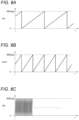
- Figs. 6A to 6C illustrate a relationship between the phases ⁇ dc, ⁇ dc2r, and ⁇ dh in the control device 4 of the PM motor 1 according to the present embodiment.
- the horizontal axis indicates time t
- the vertical axis indicates phase [deg].
- the phase ⁇ dc2r has a frequency twice that of the phase ⁇ dc.
- ⁇ dh has a much higher frequency (harmonics) than ⁇ dc and ⁇ dc2r.
- a multiphase alternating current (in the present example, three-phase alternating current) output from the inverter 2 as a control signal corresponding to the phase ⁇ dc is also referred to as a "first multiphase alternating current”.
- a multiphase alternating current (in the present example, three-phase alternating current) for position estimation corresponding to the phase ⁇ dh is also referred to as a "second multiphase alternating current”. It is noted that, when position estimation of the rotor is performed in a state in which the rotor of the PM motor is stopped, only the second multiphase alternating current is output from the inverter 2.
- the result is output in a state in which the second multiphase alternating current is superposed on the first multiphase alternating current.
- the output frequency of the voltage commands Vuh, Vvh, and Vwh from the position estimator 15 is greater than the output frequency of the voltage commands Vu0, Vv0, and Vw0 from the inverse coordinate converter 8 illustrated in Fig. 3 .
- a process for position estimation is executed in a shorter cycle than that of a process related to rotation driving.
- Figs. 7(a) to 7(d) illustrates an example of a detection waveform in the position estimator 15.
- the horizontal axis indicates time t, which corresponds with each other in Figs. 7(a) to 7(d) .
- Ts indicates a control cycle for position estimation, and is specified in advance. In the case of Ts, for example, a calculation processing cycle degree of the control device 4 is set. Therefore, when the processing speed of the control device 4 is high, Ts can be set shorter.
- the vertical axis indicates the phase ⁇ dh of the harmonic voltage, and here, a step width is set in 60° increments.
- ⁇ dh is repeated between the values of 0°, 60°, 120°, 180°, 240°, and 300°.
- the voltage command Vh is set only for the dh axis by the harmonic voltage setter 17 and the zero setter 18 illustrated in Fig. 4 .
- the set voltage is converted into harmonic voltage commands Vuh, Vvh, and Vwh based on ⁇ dh from the harmonic phase generator 16. As illustrated in Fig.
- the harmonic voltage commands Vuh, Vvh, and Vwh are added to (superposed on) the three-phase voltage commands Vu0, Vv0, and Vw0, respectively, and input to the PWM controller 10 as Vu1, Vv1, and Vw1.
- values plotted with black circles (•) correspond to calculation results of the Fourier integration in each section of Ts.
- the phase of the waveform varies depending on the rotor position.
- the harmonic current value Iqh is generated with a cycle twice that of ⁇ dh. In this manner, by observing the harmonic current value Iqh and determining its phase, it is possible to estimate the rotor phase ⁇ d, that is, the rotor position.
- Fig. 7(d) illustrates signal waveforms respectively output by the sine signal generator 19 and the cosine signal generator 20 based on the harmonic phase ⁇ dh illustrated in Fig. 7(a) .
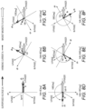
- Figs. 7(b) and 7(c) The principle of generating the waveforms in Figs. 7(b) and 7(c) will be described in more detail using Figs. 8A to 8F and 9A to 9F .
- the direction of the magnet magnetic flux ⁇ corresponds to the direction of the d axis, and the direction perpendicular thereto corresponds to the direction of the q axis.
- the superposed voltage Vh indicates the voltage applied to the PM motor based on the harmonic voltage commands Vuh, Vvh, and Vwh described above.
- the rotor of the PM motor 1 is assumed to rotate at a low speed, and ⁇ d is assumed to be stationary compared to a change in ⁇ dh. That is, the following description is based on the assumption that ⁇ dh is switched in sequence in a state in which the rotor is stopped at a certain rotation angle (position). This is based on the relationship illustrated in Figs. 6A and 6C .
- the harmonic superposed voltage Vh is applied in the positive direction on the d axis
- the harmonic current Ih is observed only on the dh axis and is not generated on the qh axis.
- the harmonic current value Iqh on the qh axis is 0.
- the harmonic current Ih is inclined in the negative direction of the dh axis with respect to the dh axis.
- the harmonic current value Iqh on the qh axis is observed as a negative value.
- the inclination of the harmonic current Ih at this time is a phenomenon that can occur in the PM motor of the configuration of any one of the surface magnet rotor or the embedded magnet rotor each having different saliency, as illustrated in Figs. 1B and 1C . In the present invention, this phenomenon is applied to perform position estimation of the rotor.
- the harmonic current Ih is inclined in the positive direction of the qh axis with respect to the dh axis. Therefore, the harmonic current value Iqh on the qh axis is observed as a positive value.
- the harmonic current Ih is observed only on the dh axis and is not generated on the qh axis. That is, as illustrated in Fig. 8A , the harmonic current value Iqh on the qh axis is 0.
- the harmonic current Ih is inclined in the negative direction of the qh axis with respect to the dh axis. Therefore, Iqh on the qh axis is observed as a negative value.
- the harmonic current Ih is inclined in the positive direction of the qh axis with respect to the dh axis. Therefore, Iqh on the qh axis is observed as a positive value.
- Iqh can be observed as a cyclical value by a relationship between the value of ⁇ dh and the rotor position, and the rotor position can be estimated based on the observation result.
- ⁇ d 45°
- the direction of the magnet magnetic flux ⁇ that is, the direction of the d axis
- the harmonic current Ih is inclined in the positive direction of the qh axis with respect to the dh axis. Therefore, Iqh on the qh axis is observed as a positive value.
- the harmonic current Ih is inclined in the negative direction of the qh axis with respect to the dh axis.
- the harmonic current value Iqh on the qh axis is observed as a negative value.
- the harmonic current Ih is inclined in the negative direction of the qh axis with respect to the dh axis.
- the harmonic current value Iqh on the qh axis is observed as a negative value.
- the harmonic current Ih is inclined in the positive direction of the qh axis with respect to the dh axis. Therefore, the harmonic current value Iqh on the qh axis is observed as a positive value.
- the harmonic current Ih is inclined in the negative direction of the qh axis with respect to the dh axis.
- the harmonic current value Iqh on the qh axis is observed as a negative value.
- the harmonic current Ih is inclined in the negative direction of the qh axis with respect to the dh axis.
- the harmonic current value Iqh on the qh axis is observed as a negative value.
- the harmonic current value Iqh can be observed for two cycles. In this case, it is not necessary to observe two cycles, and position estimation of the rotor may be performed when one cycle of the harmonic current value Iqh can be observed. In addition, in order to improve estimation accuracy, after the observation cycle of the harmonic current value Iqh is made longer (for example, three cycles or more), position estimation of the rotor may be performed.
- the observation result of the harmonic current value Iqh according to ⁇ dh is used as phase information to calculate the actual rotor phase ⁇ d of the PM motor 1.
- Fourier integration is used to estimate the rotor phase ⁇ d based on the harmonic current value Iqh.
- Fourier integration is implemented by the sine signal generator 19, the cosine signal generator 20, the integrators 21a and 21b, and the average value calculators 22a and 22b in the configuration of the position estimator 15 illustrated in Fig. 4 .
- a series of processes by these corresponds to Fourier integration, and as a result, the magnitudes of the sine and cosine components included in the harmonic current value Iqh can be obtained.
- the phase ⁇ dc2r can be obtained from these sine and cosine components by the arctangent calculator 23, and this value corresponds to the actual rotor phase.
- phase ⁇ dc2r which is the estimated position of the rotor estimated by the position estimator 15, is estimated using the harmonic current, so it is assumed that the phase includes a noise component. Therefore, in the present embodiment, in order to suppress the influence of noise, phase locked loop (PLL) control by the KPLL controller 12 is used to give a certain band to the response, thereby removing the noise components.
- PLL phase locked loop
- the phase ⁇ dc2r obtained by applying harmonics changes at a frequency twice that of ⁇ d, as described above with reference to Fig. 8 .
- the saliency of the rotor acts equally on both the N pole and the S pole of the permanent magnet provided in the rotor, so that the frequency change is always twice as large.
- the double gain 14 is provided, the estimated phase ⁇ dc is doubled in advance, and deviation between the doubled phase ⁇ dc and ⁇ dc2r is obtained by the adder/subtractor 11c. Then, the PLL control is performed on the deviation by the KPLL controller 12.
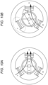
- Figs. 10A and 10B illustrate configuration examples of the PM motor to which the method according to the present embodiment can be applied.
- the PM motor having two poles and three phases is illustrated.
- the PM motor has a structure in which three-phase windings of a U-phase, a V-phase, and a W-phase are wound around a stator slot.
- the PM motor illustrated here has no saliency like the surface magnet rotor, as described with reference to Figs. 1A to 1C (that is, saliency is so weak that a change cannot be detected by the method of the related art).
- a white arrow indicates a direction of the magnetic flux when current is applied to each phase
- a black arrow indicates a direction of a magnetic field line when current is applied to each phase.
- Figs. 11A and 11B are graphs illustrating a change in inductance of the stator and rotor constituting the PM motor.
- the horizontal axis indicates the rotation angle (actual phase) of the rotor that rotates over time
- the vertical axis indicates inductance.
- the magnetic circuit of the magnetic flux caused by the current is different from that of a case in which current flows from the W-phase to the U-phase and current does not flow from the V-phase to the U-phase ( Fig. 10B ).
- the V-phase is a vacant coil.
- the magnetic circuit of the magnetic flux in the PM motor changes depending on the current flow state of each phase. As a result, the inductance of the stator appears to fluctuate in the circuit of the PM motor.
- the inductance of the stator changes depending on the energized phase, as illustrated in Fig. 11A , it has a cyclicality of 60°.
- the inductance of the d axis and the q axis is converted as illustrated in Fig. 11B by saliency.
- it has a cyclicality of 180°.
- the range of the change in inductance is smaller in the rotor than in the stator. In other words, there is a difference in the change in inductance between the stator and the rotor.
- the rotor position is estimated using saliency.
- the harmonic superposition phase ⁇ dh is set at a given interval, that is, at a cycle of 60°, as illustrated in Fig. 7(a) , so as to fix the value of the stator inductance. That is, the phase is fixed at the position plotted by a black circle (•) in Fig. 11A .
- the phase is fixed such that detection is performed at the position at which the inductance is the highest. As a result, it becomes possible to extract and detect only the change in the rotor inductance, and the accuracy of estimating the rotor position can be improved.
- ⁇ dh is set to 0, 60, 120, and the like, but the present invention is not limited thereto.
- other angles may be used as long as the change in the stator inductance can be fixed.
- position estimation of the rotor is performed using six patterns, but more patterns may be used to improve granularity and accuracy.
- An interval at which ⁇ dh is set may also be changed depending on the structure of the stator and rotor of the PM motor.
- a current pattern illustrated in Fig. 10A that is, a pattern with no vacant coils
- a current pattern illustrated in Fig. 10B that is, a pattern with vacant coils
- the present embodiment enables position sensorless driving of the PM motor having non-saliency (that is, weak saliency), which has been considered difficult to perform sensorless driving by harmonic superposition.
- the rotor position can be estimated.
- Figs. 12 to 14 Examples of application patterns of harmonics used in estimating the rotor position according to the present invention are illustrated in Figs. 12 to 14 .
- an example of the PM motor having two phases and three poles will be described. It is noted that, if the number of phases or poles of the PM motor is different, the application pattern may be defined according to the configuration.
- the application patterns illustrated below illustrate an example in which all three stator coils V, U, and W are used, and no vacant coils are generated.
- Fig. 12 is a diagram illustrating an example of a superposed waveform of harmonics according to the present embodiment.
- the waveform illustrated here is an example of a 180-degree rectangular wave.
- the horizontal axis in Fig. 12 indicates time, and corresponds to each graph.
- a dashed line corresponds to an interval of Ts, and six sections indicate one cycle of the waveform as illustrated in both directions in the drawing.
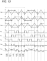
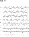
- the top three indicate harmonic voltage commands Vuh, Vvh, and Vwh for the stator coil U-phase, V-phase, and W-phase, respectively, and are illustrated here corresponding to a carrier wave by a triangular wave.
- Pu, Pv, and Pw indicate pulse signals from the PWM controller 10 corresponding to the harmonics for position estimation, which correspond to the U-phase, V-phase, and W-phase, respectively.
- Vuv indicates a line voltage in the three-phase circuit.
- Vun indicates a phase voltage of the U-phase.
- the harmonic voltage commands Vuh, Vvh, and Vwh are shifted in phase by 120°.
- the magnitudes of the voltages of the respective phases are equal to each other, and provided is a configuration of a symmetrical three-phase AC voltage with a phase difference of 120°.
- the voltage commands Vuh, Vvh, and Vwh are configured to rise and fall at the positions of positive and negative peaks of a triangular carrier wave.
- the harmonic pulse signal Pu for the stator coil U, the harmonic pulse signal Pv for the stator coil V, and the harmonic pulse signal Pw for the stator coil W indicate signal waveforms output from the PWM controller 10 to the inverter 2 when position estimation of the rotor is performed, and these pulse signals are specified such that the superposed voltage becomes constant when the position estimation is performed.
- ⁇ dh 300°, 0°, 60°, 120°, 180°, and 240° from the right, which corresponds to Fig. 8F, 8A, 8B, 8C, 8D, and 8E .
- Figs. 13 and 14 are diagrams each illustrating other examples of superposed waveforms of harmonics according to the present embodiment.
- the waveform in Fig. 13 illustrates an example of a 120-degree rectangular wave.
- the waveform in Fig. 14 illustrates an example of a sine wave.
- the configuration in Figs. 13 and 14 also has a configuration in which the phases are symmetrical.
- the carrier wave in Figs. 13 and 14 also illustrates an example of a triangular wave, and the voltage commands Vuh, Vvh, and Vwh are configured to rise and fall at the positions of positive and negative peaks of the carrier wave of the triangular wave.
- the position estimator 15 performs current detection (detection of current values lu and Iw), voltage update (update of voltage commands Vuh, Vvh, and Vwh), and Fourier integration processes for position estimation of the rotor. These processes for the position estimation may be performed with priority over the control of the rotation operation of the rotor, such as current control and speed control from the command generator 6. In other words, the signals related to the control for the position estimation may be executed by interrupting with priority.
- the present embodiment makes it possible to implement position sensorless control capable of estimating position in a low-speed range in the PM motor, regardless of a structure related to saliency of the rotor.
- the PM motor having non-saliency has been described as an example.
- the application of the present invention is not limited to the motor configuration illustrated in the above-described embodiment.
- the present invention can be applied to a slotless motor, a stepping motor, and the like.
- the present invention can also be applied to a PM motor having a concentrated winding/distributed winding coil configuration, a single-layer winding/multilayer winding coil configuration, a full-pitch winding/short-pitch winding coil configuration, and the like, as a configuration of a coil of a stator.
- the device to which the present invention can be applied may be used for PM motor control of equipment that requires operation in a low-speed range or equipment adapted for size reduction.
- the low-speed range here may be, for example, a range of speeds of 10% or less relative to the rated rotation speed of the motor.
- the motor control method according to the present embodiment may be combined with another sensorless control method in one device.
- the method according to the present invention may be used in the low-speed range, and sensorless control of the related art may be used in the high-speed range.
- a program or application for implementing the functions of one or more of the above-mentioned embodiments may be supplied to a system or device using a network or a storage medium, and one or more processors in the computer of the system or device may perform a process of reading and executing the program.
- one or more functions may be implemented by a circuit (for example, an application specific integrated circuit (ASIC) or a field programmable gate array (FPGA)) that implements the functions.
- a circuit for example, an application specific integrated circuit (ASIC) or a field programmable gate array (FPGA) that implements the functions.
- ASIC application specific integrated circuit
- FPGA field programmable gate array
- the present invention is not limited to the above-described embodiment. Further, the present invention also contemplates combinations of various configurations of the embodiments, as well as modifications and applications by those skilled in the art based on the description in the specification and well-known techniques, and is within the scope of requesting protection.
Landscapes
- Engineering & Computer Science (AREA)
- Power Engineering (AREA)
- Control Of Motors That Do Not Use Commutators (AREA)
- Control Of Ac Motors In General (AREA)
Applications Claiming Priority (2)
| Application Number | Priority Date | Filing Date | Title |
|---|---|---|---|
| JP2022125982A JP2024022711A (ja) | 2022-08-08 | 2022-08-08 | 永久磁石同期電動機の駆動装置、および制御方法 |
| PCT/JP2023/028355 WO2024034501A1 (fr) | 2022-08-08 | 2023-08-02 | Dispositif d'entraînement pour moteur synchrone à aimant permanent, et dispositif de commande |
Publications (1)
| Publication Number | Publication Date |
|---|---|
| EP4572128A1 true EP4572128A1 (fr) | 2025-06-18 |
Family
ID=89851723
Family Applications (1)
| Application Number | Title | Priority Date | Filing Date |
|---|---|---|---|
| EP23852468.0A Pending EP4572128A1 (fr) | 2022-08-08 | 2023-08-02 | Dispositif d'entraînement pour moteur synchrone à aimant permanent, et dispositif de commande |
Country Status (6)
| Country | Link |
|---|---|
| US (1) | US20260112987A1 (fr) |
| EP (1) | EP4572128A1 (fr) |
| JP (1) | JP2024022711A (fr) |
| KR (1) | KR20250033287A (fr) |
| CN (1) | CN119678362A (fr) |
| WO (1) | WO2024034501A1 (fr) |
Families Citing this family (1)
| Publication number | Priority date | Publication date | Assignee | Title |
|---|---|---|---|---|
| JP7760634B2 (ja) * | 2024-03-26 | 2025-10-27 | 本田技研工業株式会社 | 位相推定装置、及び車両 |
Family Cites Families (5)
| Publication number | Priority date | Publication date | Assignee | Title |
|---|---|---|---|---|
| JP3312472B2 (ja) | 1994-03-01 | 2002-08-05 | 富士電機株式会社 | 電動機の磁極位置検出装置 |
| JP3312520B2 (ja) | 1995-01-24 | 2002-08-12 | 富士電機株式会社 | 電動機の磁極位置検出装置 |
| JP2002078391A (ja) | 2000-08-30 | 2002-03-15 | Hitachi Ltd | 交流電動機の駆動システム |
| JP6324627B2 (ja) * | 2015-05-27 | 2018-05-16 | 三菱電機株式会社 | 交流回転機の制御装置および電動パワーステアリングの制御装置 |
| DE102021103739A1 (de) | 2021-02-17 | 2022-08-18 | Te Connectivity Germany Gmbh | Additives Fertigungssystem mit einer Mehrzahl von Fertigungsstationen und Verfahren zur additiven Fertigung einer Mehrzahl von Werkstücken |
-
2022
- 2022-08-08 JP JP2022125982A patent/JP2024022711A/ja active Pending
-
2023
- 2023-08-02 US US19/101,645 patent/US20260112987A1/en active Pending
- 2023-08-02 EP EP23852468.0A patent/EP4572128A1/fr active Pending
- 2023-08-02 KR KR1020257003864A patent/KR20250033287A/ko active Pending
- 2023-08-02 CN CN202380058136.5A patent/CN119678362A/zh active Pending
- 2023-08-02 WO PCT/JP2023/028355 patent/WO2024034501A1/fr not_active Ceased
Also Published As
| Publication number | Publication date |
|---|---|
| WO2024034501A1 (fr) | 2024-02-15 |
| JP2024022711A (ja) | 2024-02-21 |
| CN119678362A (zh) | 2025-03-21 |
| KR20250033287A (ko) | 2025-03-07 |
| US20260112987A1 (en) | 2026-04-23 |
Similar Documents
| Publication | Publication Date | Title |
|---|---|---|
| EP1876702B1 (fr) | Dispositif de régulation d'un moteur | |
| Murakami et al. | Encoderless servo drive with adequately designed IPMSM for pulse-voltage-injection-based position detection | |
| JP4674525B2 (ja) | 磁極位置推定方法及びモータ制御装置 | |
| US20170264227A1 (en) | Inverter control device and motor drive system | |
| CN101485079B (zh) | 同步机的无传感器控制装置 | |
| JP6015486B2 (ja) | 同期電動機の可変速制御装置 | |
| CN101542891B (zh) | 同步电动机的无传感器控制装置 | |
| JP4989075B2 (ja) | 電動機駆動制御装置及び電動機駆動システム | |
| JP4631672B2 (ja) | 磁極位置推定方法、モータ速度推定方法及びモータ制御装置 | |
| JP6536473B2 (ja) | 回転電機の制御装置 | |
| US11177750B2 (en) | Motor control apparatus | |
| Imai et al. | Extended EMF observer of dual three-phase permanent magnet synchronous motor operable in overmodulation drive | |
| CN106533302A (zh) | 基于马达绕组的反电动势电压控制马达的马达控制装置 | |
| EP4572128A1 (fr) | Dispositif d'entraînement pour moteur synchrone à aimant permanent, et dispositif de commande | |
| JP2010166638A (ja) | 回転電機の制御装置 | |
| JP4924115B2 (ja) | 永久磁石同期電動機の駆動制御装置 | |
| JP2007185080A (ja) | 交流電動機の回転子位相推定装置 | |
| JP5798513B2 (ja) | 永久磁石同期電動機の初期磁極位置の検出方法および装置、並びに永久磁石同期電動機の制御装置 | |
| JP2012165585A (ja) | 同期電動機駆動システム | |
| JP6422796B2 (ja) | 同期機制御装置及び駆動システム | |
| JP2022109070A (ja) | 制御装置、磁束推定装置及び磁束推定方法 | |
| US12143038B2 (en) | Rotary machine control device | |
| Mengoni et al. | Injection of third-order spatial field harmonics for sensorless speed estimation in multiphase induction motor drives | |
| JP2024022931A (ja) | 歯科用医療機器の永久磁石同期電動機の駆動装置、および制御方法 | |
| JP7472397B2 (ja) | 電力変換装置、推定器及び推定方法 |
Legal Events
| Date | Code | Title | Description |
|---|---|---|---|
| STAA | Information on the status of an ep patent application or granted ep patent |
Free format text: STATUS: THE INTERNATIONAL PUBLICATION HAS BEEN MADE |
|
| PUAI | Public reference made under article 153(3) epc to a published international application that has entered the european phase |
Free format text: ORIGINAL CODE: 0009012 |
|
| STAA | Information on the status of an ep patent application or granted ep patent |
Free format text: STATUS: REQUEST FOR EXAMINATION WAS MADE |
|
| 17P | Request for examination filed |
Effective date: 20250207 |
|
| AK | Designated contracting states |
Kind code of ref document: A1 Designated state(s): AL AT BE BG CH CY CZ DE DK EE ES FI FR GB GR HR HU IE IS IT LI LT LU LV MC ME MK MT NL NO PL PT RO RS SE SI SK SM TR |
|
| DAV | Request for validation of the european patent (deleted) | ||
| DAX | Request for extension of the european patent (deleted) |