EP4572131A1 - Motorfehlererkennung und vorhersage der verbleibenden lebensdauer - Google Patents
Motorfehlererkennung und vorhersage der verbleibenden lebensdauer Download PDFInfo
- Publication number
- EP4572131A1 EP4572131A1 EP24220042.6A EP24220042A EP4572131A1 EP 4572131 A1 EP4572131 A1 EP 4572131A1 EP 24220042 A EP24220042 A EP 24220042A EP 4572131 A1 EP4572131 A1 EP 4572131A1
- Authority
- EP
- European Patent Office
- Prior art keywords
- motor
- phase
- data
- sensor
- fault
- Prior art date
- Legal status (The legal status is an assumption and is not a legal conclusion. Google has not performed a legal analysis and makes no representation as to the accuracy of the status listed.)
- Pending
Links
Images




Classifications
-
- H—ELECTRICITY
- H02—GENERATION; CONVERSION OR DISTRIBUTION OF ELECTRIC POWER
- H02P—CONTROL OR REGULATION OF ELECTRIC MOTORS, ELECTRIC GENERATORS OR DYNAMO-ELECTRIC CONVERTERS; CONTROLLING TRANSFORMERS, REACTORS OR CHOKE COILS
- H02P29/00—Arrangements for regulating or controlling electric motors, appropriate for both AC and DC motors
- H02P29/02—Providing protection against overload without automatic interruption of supply
- H02P29/024—Detecting a fault condition, e.g. short circuit, locked rotor, open circuit or loss of load
-
- G—PHYSICS
- G01—MEASURING; TESTING
- G01R—MEASURING ELECTRIC VARIABLES; MEASURING MAGNETIC VARIABLES
- G01R31/00—Arrangements for testing electric properties; Arrangements for locating electric faults; Arrangements for electrical testing characterised by what is being tested not provided for elsewhere
- G01R31/34—Testing dynamo-electric machines
- G01R31/343—Testing dynamo-electric machines in operation
-
- B—PERFORMING OPERATIONS; TRANSPORTING
- B64—AIRCRAFT; AVIATION; COSMONAUTICS
- B64D—EQUIPMENT FOR FITTING IN OR TO AIRCRAFT; FLIGHT SUITS; PARACHUTES; ARRANGEMENT OR MOUNTING OF POWER PLANTS OR PROPULSION TRANSMISSIONS IN AIRCRAFT
- B64D45/00—Aircraft indicators or protectors not otherwise provided for
Definitions
- Motors such as those used to drive pumps in various services, often experience failures related to several types of stator faults. Motor failure causes equipment downtime and subsequent reactive scheduling of maintenance. A system for detecting motor faults and predicting remaining useful life of the motor may be desired. Additionally, a fault may be accompanied by the presence of a detected feature. However, in some instances, for example where a motor is operating at a relatively high speed or torque, the feature may be detected even when the motor is still healthy. A system that can determine a current health of the motor even in such situations may be desired.
- the subject matter of this disclosure relates to methods and systems for detecting motor fault detection and predicting remaining useful life of the motor.
- the disclosed systems may receive sensor data that is provided to a model.
- the model is trained by utilizing current, speed, and/or range of load data for healthy motor operation.
- the model utilizes the sensor data to output a health index of the motor.
- the health index is then utilized to predict a future time at which the motor will be "unhealthy" (for example, may experience a fault, failure, degraded state, or other negative event). This prediction can be relayed to an operator or other user (for example, an aircraft pilot or maintenance scheduler) for further action.
- Motors often experience failures related to several types of stator faults. Motor failure causes equipment downtime and subsequent reactive scheduling of maintenance. In some examples, where the motor is installed in a system that is critical and/or where maintenance is difficult to schedule or perform, an unexpected or unpredicted failure can be especially detrimental to the overall process (for example, a motor that is driving a fuel pump in an aerospace environment, such as onboard an airplane or jet). A fault may be accompanied by the presence of a detected feature. However, in some instances, for example where a motor is operating at a relatively high speed or torque, the feature may be detected even when the motor is still healthy; this makes detection and prediction of motor faults over the life of the motor difficult.
- the disclosed systems may receive sensor data that is provided to a model.
- the model is trained by utilizing current, speed, and/or range of load data for healthy motor operation.
- a model/algorithm determines, based on the sensor data, a health index of the motor. This may include determining whether there is a fault, and may include determining a type of the fault.
- a filtering algorithm is then applied to the health index at a prognostic application to predict a future time at which the motor will be "unhealthy" (for example, may experience a fault, failure, degraded state, or other negative event). This prediction can be relayed to an operator or other user for further action.
- a notification (such as an icon appearing or an indicator light illuminating) may be presented to a pilot in the cockpit of the aircraft.
- a notification may be presented to a user (such as a maintenance scheduler user) on a user interface of a device.
- the user may schedule the motor for preventative maintenance at a time appropriate to minimize downtime of the aircraft and to replace or fix the motor before it ceases to function.
- a motor may be one of several motors. If one motor is predicted to need maintenance, a user may schedule for multiple (or all) motors of the network of motors to be replaced at the same time, to minimize downtime and prevent further faults and future maintenance on other motors.
- FIG. 1 illustrates an example system 100 for performing fault detection and remaining useful life prediction.
- the devices, applications, and systems of system 100 are configured to send and receive data (for example, to communicate) via network 122.
- network 122 may include a computer network, an enterprise intranet, the Internet, a LAN, a Wide Area Network (WAN), wireless transmission mediums, wired transmission mediums, other networks, and combinations thereof.
- network 122 is shown as a single network in FIG. 1 , this is shown as an example and the various communications described herein may occur over the same network or a number of different networks.
- a process or entity, such as aircraft 102, may include at least one motor 108.
- motor 108 is coupled to a pump 104 to drive the pump 104.
- aircraft 102 may include a plurality of (for example, a network of) pumps 104 and associated drive motors 108.
- the pump 104 is a fuel pump.
- the motor 108 is an electric motor (for example, a radial flux motor, axial flux motor, linear motor, or other appropriate type).
- motor 108 may be subject to one or more types of faults related to the motor winding.
- motor 108 may experience one or more of: an interturn fault ("IT fault,” where two turns of the same coil are shorted); phase-to-phase fault (“PP fault,” winding-to-winding fault, where leakage current flows from one phase winding to another phase winding, for example due to a degraded insulation); and/or a winding-to-ground fault (“WG fault” or phase-to-ground fault “PG fault,” where leakage current flows from phase winding to ground, for example due to degraded insulation)
- IT fault interturn fault
- PP fault phase-to-phase fault
- PG fault phase-to-ground fault
- Motor 108 and/or pump 104 may be coupled to at least one sensor 110 (for example, one sensor 110 or a plurality of sensors 110).
- the sensor 110 may be configured to receive operational information, status information, and/or other information related to motor 108. Received information may include, among others, motor current data.
- sensor 110 may be a Hall effect sensor that measures each phase current going to the motor 108.
- Sensor 110 may be included in a drive of motor 108.
- sensor 110 is a located at the output of the drive printed circuit board assembly (PCBA) and before a power supply input to the motor 110.
- PCBA drive printed circuit board assembly
- the pump 104, motor 108, and sensor(s) 110 may be included in a pump operational sub-system 106.
- pump operational sub-system 106 may also include one or more controllers (for example, motor control system 120, described below) or other platforms.
- Aircraft 102 includes a cockpit 112 from which a pilot 114 pilots the aircraft 102.
- the cockpit 112 may include various controls, screens, indicators indicator lights, and other features whereby the pilot 114 may receive information relating to aircraft 102's operation and/or may affect aircraft 102's operation.
- cockpit 114 includes a motor fault warning feature 116, which may include an indicator light, a warning icon on a screen, or another appropriate visual notification feature.
- motor fault warning feature 116 may include an audible notification feature.
- aircraft 102 includes one or more aircraft electrical and control units 118. Aircraft 102 may also include motor control system 120. In some examples, motor control system 120 includes one or more controllers for the operation of motor(s) 108. In some examples, motor control system 120 may be located within the aircraft electrical and control units 118. In some examples, motor control system 120 may be located within the pump operational sub-system 106. In some examples, motor control system 120 may be located elsewhere within aircraft 102.
- one or more controls of cockpit 112 may send data to and/or receive data from components of pump operational sub-system 106 (for example, with sensor(s) 110 and/or motor 108) directly, or via a network 112. In some examples, one or more controls of cockpit 112 may send data to and/or receive data from aircraft electrical and control units 118 directly, or via a network 112. In some examples, one or more controls of cockpit 112 may send data to and/or receive data from motor control system 120 directly, or via a network 112. In some examples, aircraft electrical and control units 118 may send data to and/or receive data from components of pump operational sub-system 106 (for example, with sensor(s) 110 and/or motor 108), or via a network 112. In some examples, motor control system 120 may send data to and/or receive data from components of pump operational sub-system 106 (for example, with sensor(s) 110 and/or motor 108), or via a network 112. In some examples, motor control system 120 may send data to and/or receive data from components of pump operational sub-
- a fault detection and remaining useful life (hereinafter "RUL") prediction platform 124 includes a diagnostic application 126 and a prognostic application 128.
- the fault detection and RUL prediction platform 124 (for examples, models and algorithms carried out by the components of diagnostic application 126 and/or prognostic application 128) may be executed within pump operational sub-system 106, within/by motor control system 120, within aircraft electrical and control units 118, within another component of aircraft 102, or from a remote location.
- fault detection and RUL prediction platform 124 includes one or more controllers.
- Fault detection and RUL prediction platform 124 may receive data (for example, at diagnostic application 126) from sensor(s) 110, in addition to data from other sources in some examples.
- Prognostic application 128 may receive data outputs from diagnostic application 126, in addition to data from other sources in some examples.
- Output data from fault detection and RUL prediction platform 124 (for examples, from diagnostic application 126 and/or prognostic application 128) may be output/sent to a cockpit 112, for example, to motor fault warning feature 116.
- Output data from fault detection and RUL prediction platform 124 may be output/sent to user interface 134, for display on a display of device 130, where it may be viewed and/or interacted with by a user 132.
- user interface 134 may include maintenance planning features, where the output of fault detection and RUL prediction platform 124 may be displayed (for example, indicating that one or more motor(s) 108 will be in need of maintenance in a certain timeframe.
- User 132 may be a maintenance worker or another employee of a maintenance enterprise, air travel enterprise, military personnel, or another user type. User 132 may utilize user interface 134 to review the output of fault detection and RUL prediction platform 124 and to schedule and/or plan required maintenance. Maintenance may include replacement of one or more components of motor(s) 108, replacement of motor(s) 108, or fixing/modifying one or more components of motor(s) 108.
- user interface 134 is a web application.
- user interface 134 is a device application.
- device 130 may be a desktop computer, a laptop computer, a tablet, a cell phone, a smart TV, a smart wearable device, or other appropriate electronic device which is capable of displaying and facilitating user interaction with the user interface 134.
- database 136 may store data from sensor(s) 110, data from components of fault detection and RUL prediction platform 124 (for example, diagnostic application 126 and/or prognostic application 128), data from a maintenance system associated with user 132, interaction data associated with user interface 134, and/or other data.
- Database 136 as described herein may be of any appropriate database type, including distributed, centralized, relational/SQL, object-oriented, column-oriented, NoSQL, cloud-based, on-premises, operational, analytical, flat-file, network, graphical, time series, multi-model, and/or other database types.
- fault detection and RUL prediction platform 124 may receive data from sensor(s) 110 directly or semi-directly through network 122.
- fault detection and RUL prediction platform 124 may receive data from sensor(s) 110 from database 136 (directly or through network 122).
- training data for training of models of fault detection and RUL prediction platform 124 may be stored in database 136.
- FIG. 2 illustrates an example architecture 200 for performing fault detection and RUL prediction, within the example system of FIG. 1 .
- a motor 202 (in some examples, an electric motor utilized to drive a pump or compressor) may be monitored by one or more sensors 204.
- the sensor 204 may gather information/data relating to the status and operation of motor 202, for example data three-phase current data and related sequence components.
- the sensor data from sensor 204 may be stored in a database in some examples.
- Sensor data from sensor 204 is received by a diagnostic application 206.
- sensor data is determined continuously by sensor 204.
- sensor data is determined intermittently or periodically by sensor 204.
- sensor data is received continuously by diagnostic application 206.
- sensor data is received intermittently or periodically by diagnostic application 206.
- Diagnostic application 206 receives sensor data from sensor 204.
- a controller for example, a controller of a motor control system such as motor control system 120
- diagnostic application 206 determines health of motor 202 (for example, winding health) based on the sensor data.
- the sensor data bay be used as an indicator of fault occurrence, fault severity, and/or fault type.
- receipt of a negative sequence component may be indicative of a PP fault and/or IT fault.
- receipt of a zero sequence component (or higher) may be indicative of a PG fault. The value of the sequence component may indicate severity of the fault.
- Diagnostic application 206 generates an output health index of the motor 202.
- the health index is received by a prognostic application 208.
- diagnostic application 206 operates periodically (for example, a given number of seconds, minutes, hours, or days between runs). In some examples, diagnostic application 206 operates continuously.
- Prognostic application 208 receives the health index from diagnostic application 206.
- a controller for example, a controller of a motor control system such as motor control system 120
- prognostic application 208 may predict a performance trend and/or a time at which the motor 202 (for example, the motor winding) will reach a degraded state.
- the prediction from prognostic application 208 may be automatically communicated to a receiver user (for example, to a user via a user interface, or to a pilot via an indicator) as an alarm or notification 210.
- This notification of the prediction may alert the receiver user that a failure is imminent (and therefore that the motor should be shut down and/or maintained immediately), or alternatively that maintenance should be scheduled for a non-imminent time in the future that maximizes motor life while minimizing downtime.
- This allows for efficient scheduling of predictive maintenance of motor 202 and, in some examples, other motors within the same network/group of motors. This allows for cost-effective operation of aircraft and maintenance groups, as well as helping to ensure safe operation of the motors in an environment where safety is particularly crucial.
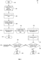
- FIG. 3 illustrates an example flowchart 300 for a diagnostic application 206 of the architecture 200 of FIG. 2 .
- the flowchart 300 begins, and a training process can begin.
- the training process encompasses operations 302 through 312, and may be performed periodically (for example, as new training data is received or generated, as motor type or motor components change, etc.).
- the diagnostic application 206 may comprise a machine learning/artificial intelligence model to generate the appropriate model/algorithm to apply to the ultimately received sensor data.
- training sensor data is received (for example, including three phase current data).
- This training sensor data may be data collected from an actual motor over its RUL in some examples.
- data from a motor-life simulation program or model may be utilized.
- the simulation data can be gathered for a healthy motor operation, and for fault operations (where different types of faults are intentionally simulated and the associated simulated sensor data is gathered).
- This motor-life simulation data can then be validated against actual motor data. Generating simulation data and then validating the simulated data allows for adequate training data to be collected in a time-effective manner.
- the machine learning model may learn from this training data which currents indicate faults and which indicate health, as well as severity and type of fault.
- lp phase positive sequence indicator
- ln phase negative sequence indicator
- lz phase zero sequence indicator
- f frequency of the motor current
- coefficients r a weight vector that is multiplied to the system matrix A to estimate negative and zero sequence
- a system matrix A a system matrix having columns as a function of lp and Ns both linear and nonlinear terms
- a band is defined around the estimated lp and lz. This band may define a threshold within which the motor is defined as having a healthy operating status.
- the training exercise may be completed. The training process may be repeated periodically as desired. In some examples, the training process may be continuous or intermittent.
- the model may be trained using healthy test data to estimate r. Once the model is trained, when it is applied to a new set of data, the value of lz and ln for healthy case can be estimated and any deviation from these numbers indicate a presence of fault in a system (PP/IT/PG), as further described below.
- Operations 314 through 328 may correspond to the model receiving sensor data from an actual installed motor, and applying the diagnostics model/algorithm that was learned in the training process.
- a system matrix is computed, and ln and lz are estimated.
- actual ln and lz values are calculated.
- a determination may be made whether the actual ln is within the defined specified range (based on the band defined at operation 310).
- ln may be considered to be a "Change in Negative sequence with respect to baseline"; that is, it may represent the change in the sequence component that is being monitored (the negative sequence). The change may be either an increase or a decrease. Therefore, in some examples, an absolute value of the change in the value may be utilized.
- lz may be considered to be a "Change in Zero sequence with respect to baseline"; that is, it may represent the change in the sequence component that is being monitored (the zero sequence).
- the change may be either an increase or a decrease. Therefore, in some examples, an absolute value of the change in the value may be utilized.
- a generated health indicator comprises one or more of these final determinations 328, 326, 322.
- the process of operations 314 through 328 my occur intermittently/periodically or continuously, generating health indicators of the motor at different time based on updated sensor data that is received.
- FIG. 4 illustrates an example architecture 400 for a prognostic application 208 of the architecture 200 of FIG. 2 .
- a health indicator is received from a diagnostic application.
- the health indicator may indicate a fault, a type of fault, no fault, and/or other information related to motor health.
- health indicators of the motor are tracked over time as they are received. In some examples, health indicators are continuously monitored. In some examples, health indicators are periodically monitored.
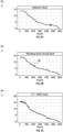
- FIG. 5A illustrates an example health indicator trend 500 over time for an interturn (IT) fault.
- FIG. 5B illustrates an example health indicator trend 502 over time for a winding short circuit (WSC) fault.
- FIG. 5C illustrates an example health indicator trend 504 over time for both an interturn (IT) fault and a winding short circuit (WSC) fault.
- These health indicator trends illustrate that although various data points may appear to be outliers or noise (for example, see point 506), the health indicators follow an overall degradation trend over time, as the health indicator value (Y-axis) decreases as the lifetime of the pump increases (X-axis).
- the health indicator data points are processed in a moving average model, where the number of measurements to be input into the moving average model and the fading memory Kalman filter is identified such that the degradation trend is not lost due to the averaging step(s) occurring in the moving average model.
- This moving average step may function to smooth out the health indicator trends and reduce the effects of outlier/noise datapoints.
- the number of inputs may be determined via a monotonicity check of an increasing degradation trend/forecast.
- a fading memory Kalman filter is applied to the de-noised data trend.
- the algorithm of the Kalman filter utilizes a fading memory, where increased weights are assigned to more recent data points, so that sudden changes in degradation due to motor usage can be captured efficiently.
- a forecast (predicted) RUL for the motor is generated.
- the forecast RUL may be generated by utilizing filter parameters for a time-to-failure threshold.
- an alarm or notification may be sent based on forecast RUL.
- the alarms/notifications may be sent at differing thresholds. For example, if a forecast RUL is below a predetermined threshold number of hours, then a notification/alarm may be sent. The type of notification or alarm may also be determined based on the forecast RUL.
- a notification may be sent to a user interface; if the forecast RUL is below both the first higher predetermined threshold and below a second lower predetermined threshold (indicating a more imminent predicted failure/fault), then both a notification to a user interface and an alarm to a cockpit may be sent.
- the model may be trained using training data that maximizes the algorithm accuracy at that desired timeframe (i.e. a certain desired number of hours of motor lifetime).
- FIG. 6 illustrates an example plot 600 of predicted (forecast) RUL (Y-axis, hours) of a motor compared to actual RUL data.
- Plot 600 illustrates that the predicted RUL trends very closely with the actual RUL for the motor from the point representing about 50% of degraded life of the motor stator (roughly between 300 hours and 400 hours of current time in this particular example).
- the operation of the motor may be altered based on a different stress or load being applied to the motor during operation.
- the model may be retrained as described above on new training data that considers the altered operation of the motor.
- New sensor data may then be received at the diagnostic application, which will predict updated health indicators (on an associated new, different degradation trend).
- the prognostic application will forecast a new predicted RUL. If the stress is increased, the predicted RUL may forecast a lesser predicted RUL (e.g. a sooner failure or end of life). This may, in some examples, be used to proactively alter motor operation to extend the RUL of the motor. For example, if motor operation is altered (for example, load decreased) so that stress on the motor is decreased, then the predicted RUL may increase (e.g. a later failure or end of life).
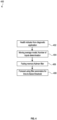
- FIG. 7A illustrates an example method for training a fault detection and remaining useful life prediction model, according to an example.
- the operations of FIG. 7A may be carried out by a controller, for example, a controller of a motor control system such as motor control system 120.
- a first subset of training data is received, wherein the first subset of training data includes sensor data of an actual motor, wherein the sensor data of the motor comprises motor current data.
- a second subset of training data is generated at a motor simulation program or model (the second subset of data comprises motor current data of a simulated motor).
- the first subset of training data may include data relating to a healthy pump operation, may include data relating to one or more faults, or may include both healthy operation and fault data.
- the second subset of training data may include data relating to a healthy pump operation, may include data relating to one or more faults, or may include both healthy operation and fault data.
- the second subset of data is validated against the first subset of training data.
- a set of training data is received, the set of training data including the first subset of training data (related to the actual pump) and the second subset of training data (simulation-generated).
- the set of training data may include motor current data.
- various factors may be estimated and calculated as described in further detail above, including at least a phase negative sequence and a phase zero sequence (of the set of training data).
- At operation 712 at least a phase negative sequence band and a phase zero sequence band are defined.
- other bands such as a phase positive sequence band may also be defined.
- FIG. 7B illustrates an example method for performing fault detection and remaining useful life prediction, according to an example.
- the operations of FIG. 7B may be carried out by a controller, for example, a controller of a motor control system such as motor control system 120.
- a controller for example, a controller of a motor control system such as motor control system 120.
- a plurality of sensor data points are received from at least one sensor associated with a motor.
- Each of the plurality of sensor data points may be associated with a time at which the sensor data was taken from the motor.
- the sensor data points comprise motor current data.
- the motor is coupled to a pump, for example, to drive the pump.
- the motor is an electric motor.
- the motor is installed in an aerospace environment.
- the pump is a fuel pump.
- the motor is one of a plurality of motors, the pump is one of a plurality of motors, each of the plurality of motors is coupled to one of the plurality of pumps, and a plurality of sensor data points is received for each of the plurality of motors.
- various factors may be estimated and calculated as described in further detail above, including at least a phase negative sequence and a phase zero sequence.
- phase negative sequence does not fall within a predetermined phase negative sequence band, and therefore that there is at least one of a phase-to-phase fault or an interturn fault in the motor. In some examples, it may be determined that the phase zero sequence does not fall within a predetermined phase zero sequence band, and therefore that there is a phase-to-ground fault in the motor. In some examples, it may be determined that the phase zero sequence falls within a predetermined phase zero sequence band and that the phase negative sequence falls within a predetermined phase negative sequence band; and therefore that there is no fault in the motor.
- each generated health indicator associated with the motor is received, and the health indicators form a trend (for example, a degradation trend of a motor winding).
- a moving average is applied to the health indicators of the trend, for example, to de-noise the health indicator trend data.
- a filter is applied to the de-noised, averaged health indicators.
- a RUL of the motor is forecasted based on the filtered averaged health indicators.
- the motor may be scheduled for maintenance (in some examples, the motor may be automatically scheduled; in other examples, the motor may be scheduled by a user), based on receiving the notification at the user interface. In some examples, it may be determined that the forecasted remaining useful life is below a threshold period of time, and an alarm may be automatically sent to a cockpit, wherein the alarm causes a warning light to illuminate in the cockpit.
- the operation of the motor may be altered (for example, operating factors may be adjusted to decrease stress on the motor) based at least on the forecasted remaining useful life.
- the obtained real time health index values may be received at a developed motor simulation program or model to estimate the motor winding fault severity.
- a developed motor simulation program or model may be used to estimate the motor winding fault severity.
- the approach of back feeding the obtained data (i.e. sequence components, RMS values of three phase currents, etc.) to the simulation program or model may help the user (for example, a maintenance user) to know the severity of fault within motor that led to the change in healthy index. In some examples, this aids in developing effective motor digital twins/ programs or models, especially under fault conditions.
- a motor simulation program or model user can increase fault severity for inter turn, phase to phase and phase to ground faults, and may obtain the corresponding change in the sequence components and RMS values of current. If this change matches with the actual motor change in the sequence component and RMS values, then the level of fault severity inside the motor for a given operation condition may be determined without opening the motor.
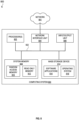
- FIG. 8 illustrates an example block diagram of a virtual or physical computing system 800.
- One or more aspects of the computing system 800 can be used to implement the systems described herein, store instructions described herein, and preform operations described herein.
- System 800 may be integrated with or comprised within a motor control system (for example, motor control system 120) as described herein.
- the computing system 800 includes one or more processors 802, a system memory 808, and a system bus 822 that couples the system memory 808 to the one or more processors 802.
- the system memory 808 includes RAM (Random Access Memory) 810 and ROM (Read-Only Memory) 812.
- RAM Random Access Memory
- ROM Read-Only Memory
- the computing system 800 further includes a mass storage device 814.
- the mass storage device 814 is able to store software instructions and data.
- the one or more processors 802 can be one or more central processing units or other processors.
- the mass storage device 814 is connected to the one or more processors 802 through a mass storage controller (not shown) connected to the system bus 822.
- the mass storage device 814 and its associated computer-readable data storage media provide non-volatile, non-transitory storage for the computing system 800.
- computer-readable data storage media can be any available non-transitory, physical device or article of manufacture from which the central display station can read data and/or instructions.
- Computer-readable data storage media include volatile and non-volatile, removable and non-removable media implemented in any method or technology for storage of information such as computer-readable software instructions, data structures, program modules or other data.
- Example types of computer-readable data storage media include, but are not limited to, RAM, ROM, EPROM, EEPROM, flash memory or other solid state memory technology, CD-ROMs, DVD (Digital Versatile Discs), other optical storage media, magnetic cassettes, magnetic tape, magnetic disk storage or other magnetic storage devices, or any other medium which can be used to store the desired information and which can be accessed by the computing system 800.
- the computing system 800 may operate in a networked environment using logical connections to remote network devices through the network 801.
- the network 801 is a computer network, such as an enterprise intranet and/or the Internet.
- the network 801 can include a LAN, a Wide Area Network (WAN), the Internet, wireless transmission mediums, wired transmission mediums, other networks, and combinations thereof.
- the computing system 800 may connect to the network 801 through a network interface unit 804 connected to the system bus 822. It should be appreciated that the network interface unit 804 may also be utilized to connect to other types of networks and remote computing systems.
- the computing system 800 also includes an input/output controller 806 for receiving and processing input from a number of other devices, including a touch user interface display screen, or another type of input device. Similarly, the input/output controller 806 may provide output to a touch user interface display screen or other type of output device.
- an input/output controller 806 for receiving and processing input from a number of other devices, including a touch user interface display screen, or another type of input device. Similarly, the input/output controller 806 may provide output to a touch user interface display screen or other type of output device.
- the mass storage device 814 and the RAM 810 of the computing system 800 can store software instructions and data.
- the software instructions include an operating system 818 suitable for controlling the operation of the computing system 800.
- the mass storage device 814 and/or the RAM 810 also store software instructions, that when executed by the one or more processors 802, cause one or more of the systems, devices, or components described herein to provide functionality described herein.
- the mass storage device 814 and/or the RAM 810 can store software instructions that, when executed by the one or more processors 802, cause the computing system 800 to receive and execute managing network access control and build system processes.
- a motor control system comprising: an electric motor coupled to a pump; at least one sensor associated with the motor, the at least one sensor providing a plurality of sensor data points associated with a timestamp; and a controller configured to: receive a plurality of sensor data points from at least one sensor, the at least one sensor associated with a motor, each of the plurality of sensor data points being associated with a time; for each of the sensor data points: determine at least (i) a phase negative sequence, and (ii) a phase zero sequence of the sensor data; and based at least on the phase negative sequence and the phase zero sequence, generate a motor health indicator associated with the time of the sensor data point; receive each of the generated health indicators, wherein the generated health indicators form a trend; apply a moving average to the health indicators of the trend; apply a filter to the averaged health indicators; and forecast a remaining useful life of the motor, based on the filtered averaged health indicators.
- Aspect 2 The motor control system of aspect 1, wherein the controller is further configured to: determine that the forecasted remaining useful life is below a threshold period of time; and automatically send a notification to a user interface.
- Aspect 3 The motor control system of any of aspects 1-2, wherein the controller is further configured to: determine that the forecasted remaining useful life is below a threshold period of time; and automatically send an alarm to a cockpit, wherein the alarm causes a warning light to illuminate in the cockpit.
- Aspect 4 The motor control system of any of aspects 1-3, wherein the sensor data points comprise motor current data.
- Aspect 5 The motor control system of any of aspects 1-4, wherein the controller is further configured to: determine that the phase negative sequence does not fall within a predetermined phase negative sequence band; and determine that there is at least one of a phase-to-phase fault or an interturn fault in the motor.
- Aspect 6 The motor control system of any of aspects 1-5, wherein the controller is further configured to: determine that the phase zero sequence does not fall within a predetermined phase zero sequence band; and determine that there is a phase-to-ground fault in the motor.
- Aspect 7 The motor control system of any of aspects 1-6, wherein the controller is further configured to: determine that the phase zero sequence falls within a predetermined phase zero sequence band; determine that the phase negative sequence falls within a predetermined phase negative sequence band; and determine that there is no fault in the motor.
- a method comprising: receiving, at a motor control system associated with a motor, a plurality of sensor data points from at least one sensor, the at least one sensor associated with the motor, each of the plurality of sensor data points being associated with a time, wherein the sensor data points comprise motor current data; for each of the sensor data points: determining at least (i) a phase negative sequence, and (ii) a phase zero sequence of the sensor data; and based at least on the phase negative sequence and the phase zero sequence, calculating a motor health indicator associated with the time of the sensor data point; receiving each of the generated health indicators, wherein the generated health indicators form a trend; applying a moving average to the health indicators of the trend; applying a filter to the averaged health indicators; and forecasting a remaining useful life of the motor, based on the filtered averaged health indicators.
- Aspect 9 The method of aspect 8, further comprising: determining that the forecasted remaining useful life is below a threshold period of time; and automatically sending a notification to a user interface.
- Aspect 10 The method of aspect 9, further comprising: scheduling the motor for maintenance, based on receiving the notification at the user interface.
- Aspect 11 The method of aspect 8, further comprising: determining that the forecasted remaining useful life is below a threshold period of time; and automatically sending an alarm to a cockpit, wherein the alarm causes a warning light to illuminate in the cockpit.
- Aspect 12 The method of any of aspects 8-11, further comprising: receiving a set of training data, the training data comprising motor current data; determining at least (i) a phase negative sequence and (ii) a phase zero sequence of the set of training data; and defining at least (i) a phase negative sequence band and (ii) a phase zero sequence band.
- Aspect 13 The method of aspect 12, further comprising: receiving a first subset of training data, wherein the first subset of training data comprises sensor data of a second motor, wherein the sensor data of the second motor comprises motor current data; generating a second subset of training data, wherein the second subset of data is generated at a motor simulation, wherein the second subset of data comprises motor current data of a simulated motor; and validating the second subset of training data against the first subset of training data, wherein the set of training data comprises the first subset of training data and the second subset of training data.
- Aspect 14 The method of aspect 12, further comprising: determining that the phase negative sequence does not fall within the phase negative sequence band; and determining that there is at least one of a phase-to-phase fault or an interturn fault in the motor.
- Aspect 15 The method of aspect 12, further comprising: determining that the phase zero sequence does not fall within the phase zero sequence band; and determining that there is a phase-to-ground fault in the motor.
- Aspect 16 The method of aspect 12, further comprising: determining that the phase zero sequence falls within the phase zero sequence band; determining that the phase negative sequence falls within the phase negative sequence band; and determining that there is no fault in the motor.
- Aspect 17 The method of any of aspects 8-16, further comprising altering the operation of the motor based at least on the forecasted remaining useful life.
- a motor control system comprising: an electric motor; at least one sensor associated with the motor, the at least one sensor providing a plurality of sensor data points associated with a timestamp, wherein the plurality of sensor data points comprises motor current data; and a controller that calculates a forecasted remaining useful life of the motor, wherein calculating the forecasted remaining useful life comprises: receiving the plurality of sensor data points from at least one sensor, the at least one sensor associated with a motor, each of the plurality of sensor data points being associated with a time; for each of the sensor data points: determining at least (i) a phase negative sequence, and (ii) a phase zero sequence of the sensor data; and based at least on the phase negative sequence and the phase zero sequence, generating a motor health indicator associated with the time of the sensor data point; receiving each of the generated health indicators, wherein the generated health indicators form a trend; applying a moving average to the health indicators of the trend; applying a filter to the averaged health indicators; and forecasting a remaining useful life of the
- Aspect 19 The motor control system of aspect 18, wherein the motor is coupled to a pump.
- Aspect 20 The motor control system of aspect 19, wherein: the motor is one of a plurality of motors, the pump is one of a plurality of motors, each of the plurality of motors is coupled to one of the plurality of pumps, and a plurality of sensor data points is received for each of the plurality of motors.
- Aspect 21 The motor control system of aspect 1, wherein the controller is further configured to: determine that the forecasted remaining useful life is below a threshold period of time; and automatically perform at least one of: send a notification to a user interface; and send an alarm to a cockpit, wherein the alarm causes a warning light to illuminate in the cockpit.
- Aspect 22 The method of aspect 8, further comprising: determining that the forecasted remaining useful life is below a threshold period of time; and automatically performing at least one of: sending a notification to a user interface; and sending an alarm to a cockpit, wherein the alarm causes a warning light to illuminate in the cockpit.
Landscapes
- Engineering & Computer Science (AREA)
- Aviation & Aerospace Engineering (AREA)
- Physics & Mathematics (AREA)
- General Physics & Mathematics (AREA)
- Power Engineering (AREA)
- Control Of Electric Motors In General (AREA)
Applications Claiming Priority (1)
| Application Number | Priority Date | Filing Date | Title |
|---|---|---|---|
| IN202311085675 | 2023-12-15 |
Publications (1)
| Publication Number | Publication Date |
|---|---|
| EP4572131A1 true EP4572131A1 (de) | 2025-06-18 |
Family
ID=93924386
Family Applications (1)
| Application Number | Title | Priority Date | Filing Date |
|---|---|---|---|
| EP24220042.6A Pending EP4572131A1 (de) | 2023-12-15 | 2024-12-16 | Motorfehlererkennung und vorhersage der verbleibenden lebensdauer |
Country Status (2)
| Country | Link |
|---|---|
| US (1) | US20250199072A1 (de) |
| EP (1) | EP4572131A1 (de) |
Families Citing this family (1)
| Publication number | Priority date | Publication date | Assignee | Title |
|---|---|---|---|---|
| US12528264B1 (en) * | 2025-05-06 | 2026-01-20 | Plastic Recovery Technologies Corporation | Smart compactor controller |
Citations (1)
| Publication number | Priority date | Publication date | Assignee | Title |
|---|---|---|---|---|
| EP2469703A2 (de) * | 2010-12-22 | 2012-06-27 | General Electric Company | System und Verfahren zur Zustandsüberwachung der synchronen Drehstrommotoren |
Family Cites Families (1)
| Publication number | Priority date | Publication date | Assignee | Title |
|---|---|---|---|---|
| GB2541682B (en) * | 2015-08-25 | 2017-09-06 | Airbus Operations Ltd | Pump health monitoring |
-
2024
- 2024-12-16 EP EP24220042.6A patent/EP4572131A1/de active Pending
- 2024-12-16 US US18/982,338 patent/US20250199072A1/en active Pending
Patent Citations (1)
| Publication number | Priority date | Publication date | Assignee | Title |
|---|---|---|---|---|
| EP2469703A2 (de) * | 2010-12-22 | 2012-06-27 | General Electric Company | System und Verfahren zur Zustandsüberwachung der synchronen Drehstrommotoren |
Non-Patent Citations (1)
| Title |
|---|
| SHIFAT TANVIR ALAM ET AL: "Remaining Useful Life Estimation of BLDC Motor Considering Voltage Degradation and Attention-Based Neural Network", IEEE ACCESS, IEEE, USA, vol. 8, 10 September 2020 (2020-09-10), pages 168414 - 168428, XP011810426, [retrieved on 20200921], DOI: 10.1109/ACCESS.2020.3023335 * |
Also Published As
| Publication number | Publication date |
|---|---|
| US20250199072A1 (en) | 2025-06-19 |
Similar Documents
| Publication | Publication Date | Title |
|---|---|---|
| US11170586B1 (en) | Fleet level prognostics for improved maintenance of vehicles | |
| JP7460545B2 (ja) | 電気機械的マシンの調子を監視して故障を予測するシステム及び方法 | |
| US10242508B2 (en) | Aircraft maintenance systems and methods for ECS fouling predictions | |
| CA3242038C (en) | Fleet level prognostics for improved maintenance of vehicles | |
| EP2277778A2 (de) | Fahrzeugsgesundheitsverwaltungssysteme und Verfahren mit prognostizierten Diagnoseindikatoren | |
| EP3312604B1 (de) | Ölrückstandsnachweiser mit adaptivem lernen | |
| US10534359B2 (en) | Aircraft management systems and methods for ECS predictive maintenance | |
| US10388087B2 (en) | System and method for improved health management and maintenance decision support | |
| CN108475445A (zh) | 多源飞行器数据的自动化融合和分析的方法和系统 | |
| CN107408226A (zh) | 资产健康评分及其使用 | |
| WO2014117967A1 (en) | Method and apparatus for deriving diagnostic data about a technical system | |
| US11549611B2 (en) | Fault prediction in valve systems through Bayesian framework | |
| EP3252682A1 (de) | Überwachen der maschinenleistung zur wartungsvorhersage | |
| US10706361B1 (en) | Hybrid feature selection for performance prediction of fluid control valves | |
| EP3745227A1 (de) | Systeme und verfahren zur vorhersage des zustandes von integrierten antriebsgeneratoren | |
| EP4572131A1 (de) | Motorfehlererkennung und vorhersage der verbleibenden lebensdauer | |
| CN112668794A (zh) | 一种不确定寿命预测信息下航空发动机的维修优化方法 | |
| Azevedo et al. | Estimation of health indicators using advanced analytics for prediction of aircraft systems remaining useful lifetime | |
| US11339763B2 (en) | Method for windmill farm monitoring | |
| US20040039560A1 (en) | Method computer program product and computer system for maintenance | |
| US11467214B2 (en) | Anomaly detection system and method for electric drives | |
| EP4325314A2 (de) | Systeme und verfahren zur schätzung des künftigen ausfallrisikos einer windturbinenkomponente unter verwendung von maschinenlernen | |
| US20260062140A1 (en) | Prescriptive alerting for aircraft component fault predictions | |
| Sanket et al. | Study on state-of-the-art preventive maintenance techniques for ads vehicle safety | |
| Bejaoui | Intelligent Monitoring and Remaining Useful Life Estimation of Industrial Systems |
Legal Events
| Date | Code | Title | Description |
|---|---|---|---|
| PUAI | Public reference made under article 153(3) epc to a published international application that has entered the european phase |
Free format text: ORIGINAL CODE: 0009012 |
|
| STAA | Information on the status of an ep patent application or granted ep patent |
Free format text: STATUS: THE APPLICATION HAS BEEN PUBLISHED |
|
| AK | Designated contracting states |
Kind code of ref document: A1 Designated state(s): AL AT BE BG CH CY CZ DE DK EE ES FI FR GB GR HR HU IE IS IT LI LT LU LV MC ME MK MT NL NO PL PT RO RS SE SI SK SM TR |
|
| STAA | Information on the status of an ep patent application or granted ep patent |
Free format text: STATUS: REQUEST FOR EXAMINATION WAS MADE |
|
| 17P | Request for examination filed |
Effective date: 20251211 |