EP4572151A1 - Systeme und verfahren für block-kronecker-basierten low-density parity check (ldpc)-code mit coderate 1/2 und kodeblocklänge von 3888 bits - Google Patents
Systeme und verfahren für block-kronecker-basierten low-density parity check (ldpc)-code mit coderate 1/2 und kodeblocklänge von 3888 bits Download PDFInfo
- Publication number
- EP4572151A1 EP4572151A1 EP24212855.1A EP24212855A EP4572151A1 EP 4572151 A1 EP4572151 A1 EP 4572151A1 EP 24212855 A EP24212855 A EP 24212855A EP 4572151 A1 EP4572151 A1 EP 4572151A1
- Authority
- EP
- European Patent Office
- Prior art keywords
- matrix
- parity check
- exponent
- binary
- values
- Prior art date
- Legal status (The legal status is an assumption and is not a legal conclusion. Google has not performed a legal analysis and makes no representation as to the accuracy of the status listed.)
- Pending
Links
Images










Classifications
-
- H—ELECTRICITY
- H03—ELECTRONIC CIRCUITRY
- H03M—CODING; DECODING; CODE CONVERSION IN GENERAL
- H03M13/00—Coding, decoding or code conversion, for error detection or error correction; Coding theory basic assumptions; Coding bounds; Error probability evaluation methods; Channel models; Simulation or testing of codes
- H03M13/03—Error detection or forward error correction by redundancy in data representation, i.e. code words containing more digits than the source words
- H03M13/05—Error detection or forward error correction by redundancy in data representation, i.e. code words containing more digits than the source words using block codes, i.e. a predetermined number of check bits joined to a predetermined number of information bits
- H03M13/11—Error detection or forward error correction by redundancy in data representation, i.e. code words containing more digits than the source words using block codes, i.e. a predetermined number of check bits joined to a predetermined number of information bits using multiple parity bits
- H03M13/1102—Codes on graphs and decoding on graphs, e.g. low-density parity check [LDPC] codes
- H03M13/1148—Structural properties of the code parity-check or generator matrix
- H03M13/116—Quasi-cyclic LDPC [QC-LDPC] codes, i.e. the parity-check matrix being composed of permutation or circulant sub-matrices
-
- H—ELECTRICITY
- H03—ELECTRONIC CIRCUITRY
- H03M—CODING; DECODING; CODE CONVERSION IN GENERAL
- H03M13/00—Coding, decoding or code conversion, for error detection or error correction; Coding theory basic assumptions; Coding bounds; Error probability evaluation methods; Channel models; Simulation or testing of codes
- H03M13/03—Error detection or forward error correction by redundancy in data representation, i.e. code words containing more digits than the source words
- H03M13/033—Theoretical methods to calculate these checking codes
- H03M13/036—Heuristic code construction methods, i.e. code construction or code search based on using trial-and-error
-
- H—ELECTRICITY
- H03—ELECTRONIC CIRCUITRY
- H03M—CODING; DECODING; CODE CONVERSION IN GENERAL
- H03M13/00—Coding, decoding or code conversion, for error detection or error correction; Coding theory basic assumptions; Coding bounds; Error probability evaluation methods; Channel models; Simulation or testing of codes
- H03M13/03—Error detection or forward error correction by redundancy in data representation, i.e. code words containing more digits than the source words
- H03M13/05—Error detection or forward error correction by redundancy in data representation, i.e. code words containing more digits than the source words using block codes, i.e. a predetermined number of check bits joined to a predetermined number of information bits
- H03M13/11—Error detection or forward error correction by redundancy in data representation, i.e. code words containing more digits than the source words using block codes, i.e. a predetermined number of check bits joined to a predetermined number of information bits using multiple parity bits
- H03M13/1102—Codes on graphs and decoding on graphs, e.g. low-density parity check [LDPC] codes
- H03M13/1148—Structural properties of the code parity-check or generator matrix
- H03M13/118—Parity check matrix structured for simplifying encoding, e.g. by having a triangular or an approximate triangular structure
- H03M13/1185—Parity check matrix structured for simplifying encoding, e.g. by having a triangular or an approximate triangular structure wherein the parity-check matrix comprises a part with a double-diagonal
-
- H—ELECTRICITY
- H03—ELECTRONIC CIRCUITRY
- H03M—CODING; DECODING; CODE CONVERSION IN GENERAL
- H03M13/00—Coding, decoding or code conversion, for error detection or error correction; Coding theory basic assumptions; Coding bounds; Error probability evaluation methods; Channel models; Simulation or testing of codes
- H03M13/65—Purpose and implementation aspects
- H03M13/6508—Flexibility, adaptability, parametrability and configurability of the implementation
- H03M13/6516—Support of multiple code parameters, e.g. generalized Reed-Solomon decoder for a variety of generator polynomials or Galois fields
Definitions
- This disclosure generally relates to systems and methods for improving an encoding process and/or a decoding process of a communications system using a quasi-cyclic-low-density parity-check (QC-LDPC) code.
- QC-LDPC quasi-cyclic-low-density parity-check
- Error correcting codes enable information data to be exchanged between a transmitter communication system and a receiver communication system in a reliable manner.
- a transmitter communication system encodes the information data to obtain a codeword.
- the codeword is encoded information data.
- the transmitter communication system transmits the codeword to the receiver communication system. Due to noise in the communication channel, the transmission received by the receiver communication system may not be identical to the transmitted codeword.
- Encoding information data allows a receiver communication system with a proper decoding process to recover the information data from the received transmission despite such noise.
- the transmitter communication system transmits parity bits to the receiver communication system.
- the parity bits allow the receiver communication system to verify whether the received transmission is a valid codeword and to correct errors in the transmission if the received transmission is not a valid codeword.
- generating parity bits involves a complex process.
- first feature in communication with or communicatively coupled to a second feature in the description that follows may include embodiments in which the first feature is in direct communication with or directly coupled to the second feature and may also include embodiments in which additional features may intervene between the first and second features, such that the first feature is in indirect communication with or indirectly coupled to the second feature.
- present disclosure may repeat reference numerals and/or letters in the various examples. This repetition is for the purpose of simplicity and clarity and does not in itself dictate a relationship between the various embodiments and/or configurations discussed.
- a parity check matrix defines a set of equations that are satisfied by any valid codeword.
- the parity check matrix may be used for encoding low density parity check ("LDPC") codes, described by Richardson and Urbanke in IEEE Transactions on Information Theory, Vol. 47, No. 2 (February 2001 ).
- LDPC low density parity check
- many wireless and wireline communication systems use LDPC as a forward error correction coding scheme.
- the longest block length (in bit) for coded data, supported in the 802.11 standards e.g., 802.11n-802.11be
- There may be a limited gain in a radio channel e.g., 2x2 multiple-input and multiple-output channels) that can be achieved using the block length of 1944.
- embodiments in the present disclosure relate to a technique to support or provide an LDPC code with the block length of 3888 and the code rate of 1/2.
- the block length of 3888 is 2 times that of the longest code supported in 802.11n-802.11be standards (e.g., the block length of 1944).
- the LDPC code has a quasi-cyclic (QC) structure which helps in efficient encoding and decoding.
- QC-LDPC codes may be a class of structured LDPC codes, which may be used in many practical applications including the IEEE 802.11n, 802.11ac, 802.11ax, 802.11be standards.
- a parity check matrix has a cyclic structure that repeats itself in a quasi-cyclic manner, which can simplify the encoding and decoding processes, making QC-LDPC codes more efficient.
- the code block size (denoted by n) refers to a total number of coded or transmitted bits as a result of encoding data using an error correction code (e.g., LDPC).
- the number of information bits (denoted by k) refers to a number of bits that carry the data to be subject to the encoding using the error correction code.
- An LDPC decoder may operate on (noisy version of ) n received bits and (ideally) recover the k information bits.
- an apparatus may include a transmitter and one or more processors.
- the one or more processors may be configured to determine a first parity check matrix of a first QC-LDPC code having a first code block size and a code rate of 1/2.
- a parity check matrix refers to a matrix that can define relationships (e.g., parity check equations or constraints) between information bits and parity bits.
- a binary parity check matrix refers to a parity check matrix in which all the entries are either 0 or 1.
- the one or more processors may be configured to determine a binary matrix (also referred to as "gamma matrix" or " ⁇ matrix”) having the same size as a size of an exponent matrix of the first parity check matrix.
- the exponent matrix of the first parity check matrix may have a dimension of 12x24 (12 rows and 24 columns) which is the same as the dimension of the binary matrix.
- the one or more processors may be configured to generate, based on the first parity check matrix and the binary matrix, a second parity check matrix of a second QC-LDPC code having a second code block size and the code rate of 1/2.
- the one or more processors may be configured to encode data using the generated second parity check matrix.
- the one or more processors may be configured to transmit, via a transmitter of the apparatus, the encoded data to another apparatus.
- the first code block size may be 1944 bits
- the second code block size may be 3888 bits.
- each of the first parity check matrix and the second parity check matrix may have an exponent matrix comprising a plurality of integers, the number of the plurality of integers being equal to the number of elements of the parity check matrix divided by z, where z is an integer representing a lifting size of the QC-LDPC code.
- Each element of the exponent matrix may correspond to a cyclic shift value of an identity matrix.
- a size of the identity matrix is z x z
- the cyclic shift value d is an integer such that -1 ⁇ d ⁇ z, where z is an integer representing a lifting size of the QC-LDPC code.
- the cyclic shift value d may represent a shifted identity matrix that is obtained by right-shifting the identity matrix by d.
- the cyclic shift value -1 may represent a null matrix of the identity matrix.
- the one or more processors may be configured to determine a plurality of sub-matrices of the binary matrix, each sub-matrix being a power of an exchange matrix of order 2.
- the one or more processors may be configured to randomize non-zero values of the binary matrix such that the binary matrix maintains to have full rank.
- the one or more processors may be configured to determine a first exponent matrix of the first parity check matrix, determine a Khatri-Rao product of the first exponent matrix and the binary matrix, and determine, based on a result of the Khatri-Rao product, a second exponent matrix of the second parity check matrix.
- the one or more processors may be configured to generate, for each element of the second exponent matrix, a shifted identity matrix of an identity matrix based on a value of each element of the second exponent matrix.
- the one or more processors may be configured to generate the second parity check matrix such that the second parity check matrix includes, as an element corresponding to each element of the second exponent matrix, the generated shifted identity matrix.
- the binary matrix may include the following set of values: [1 1111101011100111111111111111011110011111111101111 0110111110011111111111001111111111111001100 1111111001111110111010111101111100111110001111101110 1111100111101110011010111111110011111111011111111111 1 0 0 1 1 1 1 1 1 1 0 1 1 0 0 0 1 1 1 1 1 1 1 0]; and the second exponent matrix of the second parity check matrix corresponding to the binary matrix may include the following set of values: [-1 57 -1 -1 -1 -1 -1 -1 -1 50 -1 -1 11 -1 -1 -1 50 -1 -1 -1 -1 79 -1 -1 1 -1 0 -1 -1 -1 -1 -1 -1 -1 -1 -1 - 1 -1 -1 -1 -1 -1 -1 -1 -1 -1 -1 -1 -1 -1 -1 -1 -1 -1 -1 -1
- the parity check matrix, H is one way of describing a code.
- s is a vector of information bits
- G is a generator matrix
- c is the codeword that corresponds to "s.”
- a system e.g., a communication system 108 including a decoder 160 in FIG. 1
- the parity check and generator matrices for a code are related per the above matrix equations. Generally, if a parity check matrix is low density, the corresponding generator matrix will be high density, and vice versa.
- LCPC codes are accordingly characterized by low density parity check matrices and high density generator matrices. The density of a matrix relates to the number of operations that must be performed to implement one of the above equations. Although it was recognized by 1995 that LDPC codes could be used to transmit data with very few errors, i.e., with error rates as good or better than turbo codes, one disadvantage of LDPC codes is that their generator matrices were high density and that made encoding computationally intensive, rending the codes impractical for many applications.
- a parity check matrix H may be a binary matrix whose size is m ⁇ n (each of m and n is an integer). Elements of the parity check matrix are binary values.
- a block matrix or an exponent matrix may be obtained.
- Elements of the exponent matrix may be integer values which correspond to cyclic shift values of identity matrix of size z ⁇ z.
- the generator matrix G may have a size n ⁇ k in binary form (e.g., elements of the generator matrix G are binary values).
- a binary QC-LDPC code LDPC (n, R) may be characterized by the null space of an n(1-R) ⁇ n parity check matrix H.
- the parity check matrix H may be a binary sparse matrix which includes a set of circulant matrices of size z ⁇ z.
- Any other integer value d in [1,z-1] may correspond (or map) to a matrix cyclically right shifted from I(z).
- an encoder can produce codewords using a generator matrix (e.g., using Equation 2).
- an encoder can use the parity check matrix (rather than the generator matrix) to produce codewords from vectors of information bits.
- the parity check matrix H may have sub-matrices A, B, C, D, T, E.
- An upper area O of the sub-matrix T may correspond to an area in which the matrix contains all zeroes, and the other areas may represent locations that can contain ones.
- wireless communication e.g., wireless local area network (WLAN) conforming to any IEEE 802.11 standard
- principles disclosed herein are applicable to other types of communication (e.g., wired communication) or any process that performs encoding for LDPC codes.
- a system and/or a method can generate LDPC codes having code rate of 3/4 using Khatri-Rao lifting (e.g., using Khatri-Rao product).
- the system can use a base LDPC code (as mother code) to recursively construct LDPC codes having a block length that is double the block length of the base LDPC code.
- Each entry in P may be an integer value, corresponding to a cyclic shift value of an identity matrix of size z ⁇ z.
- the matrix ⁇ whose non-zero values (1) may be randomized such that the rank of the binary matrix maintains to be full rank while the binary matrix conforms to good LDPC code performances (e.g., achieving low packet error rates).
- the system can perform a computer search (e.g., search using one or more processors) to identify the most optimal ⁇ that can yield the least packet error performance (e.g., packet error rate (PER)).
- PER packet error rate
- the matrix ⁇ can maintain to have full rank, which equals 24/(1-R), for a Wi-Fi code with code rate R.
- the rank of a matrix refers to a maximal number of linearly independent columns of the matrix or a dimension of the vector space generated by the columns of the matrix.
- Khatri-Rao product is an extension to the operation of block wise Kronecker products when the involved matrices are suitably partitioned.
- A ( A i,j ) be partitioned with A i,j of order u i ⁇ v j as (i, j) th sub-matrix block
- Extension to block wise Kronecker products when the involved matrices can be well partitioned.
- the system can perform (e.g., calculate, compute) Khatri-Rao lifting as follows.
- P ⁇ E(H) be an exponent matrix corresponding to a parity check matrix H of a QC-LDPC code.
- the exponent matrix may include integer values between -1, 0, ..., z-1 where z is a design parameter of the code.
- the parity check matrix H can be obtained from the P matrix, by cyclic shifting identity matrix I z ⁇ z by the constituent entries of P.
- the system can determine (e.g., calculate, compute, obtain) a new code matrix ⁇ using Equation 15 as follows.
- H ′ H ⁇ J ⁇ ⁇ ⁇ J ⁇ 1 uxv ⁇ ⁇
- ⁇ is the Khatri-Rao product operation
- ⁇ is a binary matrix
- the system can generate (e.g., calculate, compute, obtain) a (new) parity check code by calculating a Khatri-Rao product of a parity check matrix (of size m ⁇ n) of a base code and a binary (random) matrix ⁇ (using Equation 16).
- the system may determine the binary matrix ⁇ by iteratively changing an entry of the matrix and finding one or more best matrices in terms of the number of shortest loops and/or packet error performance (see FIG. 10 ).
- the system can define (e.g., calculate, compute, obtain, generate) the base code as a parity check matrix H or an exponent matrix E(H) as in QC-LDPC code.
- the system can calculate (e.g., generate, compute, obtain, determine) the binary matrix ⁇ , which has the same size as E(H).
- the matrix ⁇ can have the same size as H.
- the matrix ⁇ can internally include sub-matrices which are powers of exchange matrix J(2).
- the binary matrix ⁇ whose non-zero values (e.g., value "1") can be randomized such that the resulting matrix conforms to good LDPC code performances (e.g., packet error performance).
- binary matrix ⁇ are shown in FIG. 7 , but the present disclosure is not limited thereto and any suitable binary matrix ⁇ can be used to generate a QC-LDPC code.
- Examples of exponent matrix E(H) and parity check matrix H are shown in FIG. 8A and FIG.
- the system can validate a binary ⁇ matrix from a given parity check matrix and a base matrix.
- the system can validate a binary ⁇ matrix based on performance of the a given parity check matrix and the base matrix.
- the binary ⁇ matrix can be any binary matrix ⁇ which are full rank.
- a matrix (say matrix A) is full rank if the rank of the matrix A is the highest possible for a matrix of the same size as the matrix A.
- Embodiments in the present disclosure have at least the following advantages and benefits.
- the block length (e.g., 3888 bits) of an QC-LDPC code is at least 2 times that of the longest code supported in 802.11n-802.11be standards (e.g., 1994 bits).
- This QC-LDPC code can provide about 2dB gain in 2x2 MIMO (multiple input multiple output) channels and the gains are consistent across all modulation schemes with or without beamforming.
- embodiments in the present disclosure can provide useful techniques for providing significant gains (e.g., 0.5dB-1.2dB gain in SNR (signal to noise ratio) over existing codes) across all modulation schemes.
- the block length (e.g., 3888 bits) of an QC-LDPC code is at least 2 times that of the longest code supported in 802.11n-802.11be standards (e.g., 1994 bits).
- This QC-LDPC code can provide about 2dB gain in 2x2 MIMO channels and the gains are consistent across all modulation schemes with or without beamforming.
- codes generated using systems and/or methods according to embodiments in the present disclosure can help in parallel decoding and re-use of several blocks of mother code.
- the communication system 105 includes a baseband circuitry 110 and a transmitter circuitry 120
- the communication system 108 includes a baseband circuitry 150 and a receiver circuitry 140.
- the communication system 105 is considered a transmitter communication system
- the communication system 108 is considered a receiver communication system.
- These components operate together to exchange data (e.g., messages or frames) through a wireless medium.
- These components are embodied as application specific integrated circuit (ASIC), field programmable gate array (FPGA), or any combination of these, in one or more embodiments.
- ASIC application specific integrated circuit
- FPGA field programmable gate array
- the communication systems 105, 108 include more, fewer, or different components than shown in FIG. 1 .
- each of the communication systems 105, 108 includes transceiver circuitry to allow bi-directional communication between the communication systems 105, 108 or with other communication systems.
- each of the communication systems 105, 108 may have configuration similar to that of a computing system 2000 as shown in FIG. 2 .
- the baseband circuitry 110 of the communication system 105 is a circuitry that generates the baseband data 115 for transmission.
- the baseband data 115 includes information data (e.g., signal(s)) at a baseband frequency for transmission.
- the baseband circuitry 110 includes an encoder 130 that encodes the data, and generates or outputs parity bits.
- the baseband circuitry 110 (or encoder 130) obtains a generator matrix or a parity check matrix, or uses a previously produced generator matrix or a previously produced parity check matrix, and encodes the information data by applying the information data to the generator matrix or the parity check matrix to obtain a codeword.
- the baseband circuitry 110 stores one or more generator matrices or one or more parity check matrices that conform to any IEEE 802.11 standard for WLAN communication.
- the baseband circuitry 110 retrieves the stored generator matrix or the stored parity check matrix in response to detecting information data to be transmitted, or in response to receiving an instruction to encode the information data.
- the baseband circuitry 110 generates the parity bits according to a portion of the generator matrix or using the parity check matrix, and appends the parity bits to the information bits to form a codeword.
- the baseband circuitry 110 generates the baseband data 115 including the codeword for the communication system 108, and provides the baseband data 115 to the transmitter circuitry 120.
- the transmitter circuitry 120 of the communication system 105 includes or corresponds to a circuitry that receives the baseband data 115 from the baseband circuitry 110 and transmits a wireless signal 125 according to the baseband data 115.
- the transmitter circuitry 120 is coupled between the baseband circuitry 110 and an antenna (not shown).
- the transmitter circuitry 120 up-converts the baseband data 115 from the baseband circuitry 110 onto a carrier signal to generate the wireless signal 125 at an RF frequency (e.g., 10 MHz to 60 GHz), and transmits the wireless signal 125 through the antenna.
- an RF frequency e.g. 10 MHz to 60 GHz
- the receiver circuitry 140 of the communication system 108 is a circuitry that receives the wireless signal 125 from the communication system 105 and obtains baseband data 145 from the received wireless signal 125.
- the receiver circuitry 140 is coupled between the baseband circuitry 150 and an antenna (not shown). In this configuration, the receiver circuitry 140 receives the wireless signal 125 though an antenna, and down-converts the wireless signal 125 at an RF frequency according to a carrier signal to obtain the baseband data 145 from the wireless signal 125. The receiver circuitry 140 then provides the baseband data 145 to the baseband circuitry 150.
- the baseband circuitry 150 of the communication system 108 includes or corresponds to a circuitry that receives the baseband data 145 from the receiver circuitry 140 and obtains information data from the received baseband data 145.
- the baseband circuitry 150 includes a decoder 160 that extracts information and parity bits from the baseband data 145. The decoder 160 decodes the baseband data 145 to obtain the information data generated by the baseband circuitry 110 of the communication system 105.
- each of the baseband circuitry 110 may be as one or more processors, application specific integrated circuit (ASIC), field programmable gate array (FPGA), or any combination of them.
- ASIC application specific integrated circuit
- FPGA field programmable gate array
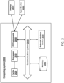
- FIG. 2 is a schematic block diagram of a computing system, according to an embodiment.
- An illustrated example computing system 2000 includes one or more processors 2010 in direct or indirect communication, via a communication system 2040 (e.g., bus), with memory 2060, at least one network interface controller 2030 with network interface port for connection to a network (not shown), and other components, e.g., input/output ("I/O") components 2050.
- the processor(s) 2010 will execute instructions (or computer programs) received from memory.
- the processor(s) 2010 illustrated incorporate, or are connected to, cache memory 2020. In some instances, instructions are read from memory 2060 into cache memory 2020 and executed by the processor(s) 2010 from cache memory 2020.
- the computing system 2000 may not necessarily contain all of these components shown in FIG. 2 , and may contain other components that are not shown in FIG. 2 .
- the processor(s) 2010 may be any logic circuitry that processes instructions, e.g., instructions fetched from the memory 2060 or cache 2020.
- the processor(s) 2010 are microprocessor units or special purpose processors.
- the computing device 2050 may be based on any processor, or set of processors, capable of operating as described herein.
- the processor(s) 2010 may be single core or multi-core processor(s).
- the processor(s) 2010 may be multiple distinct processors.
- the memory 2060 may be any device suitable for storing computer readable data.
- the memory 2060 may be a device with fixed storage or a device for reading removable storage media. Examples include all forms of volatile memory (e.g., RAM), non-volatile memory, media and memory devices, semiconductor memory devices (e.g., EPROM, EEPROM, SDRAM, and flash memory devices), magnetic disks, magneto optical disks, and optical discs (e.g., CD ROM, DVD-ROM, or Blu-Ray ® discs).
- a computing system 2000 may have any number of memory devices 2060.
- the cache memory 2020 is generally a form of computer memory placed in close proximity to the processor(s) 2010 for fast read times. In some implementations, the cache memory 2020 is part of, or on the same chip as, the processor(s) 2010. In some implementations, there are multiple levels of cache 2020, e.g., L2 and L3 cache layers.
- the network interface controller 2030 manages data exchanges via the network interface (sometimes referred to as network interface ports).
- the network interface controller 2030 handles the physical and data link layers of the OSI model for network communication. In some implementations, some of the network interface controller's tasks are handled by one or more of the processor(s) 2010. In some implementations, the network interface controller 2030 is part of a processor 2010. In some implementations, the computing system 2000 has multiple network interfaces controlled by a single controller 2030. In some implementations, the computing system 2000 has multiple network interface controllers 2030. In some implementations, each network interface is a connection point for a physical network link (e.g., a cat-5 Ethernet link).
- the network interface controller 2030 supports wireless network connections and an interface port is a wireless (e.g., radio) receiver or transmitter (e.g., for any of the IEEE 802.11 protocols, near field communication "NFC", Bluetooth, ANT, or any other wireless protocol).
- the network interface controller 2030 implements one or more network protocols such as Ethernet.
- a computing device 2050 exchanges data with other computing devices via physical or wireless links through a network interface.
- the network interface may link directly to another device or to another device via an intermediary device, e.g., a network device such as a hub, a bridge, a switch, or a router, connecting the computing device 2000 to a data network such as the Internet.
- the computing system 2000 may include, or provide interfaces for, one or more input or output (“I/O") devices.
- I/O devices include, without limitation, keyboards, microphones, touch screens, foot pedals, sensors, MIDI devices, and pointing devices such as a mouse or trackball.
- Output devices include, without limitation, video displays, speakers, refreshable Braille terminal, lights, MIDI devices, and 2-D or 3-D printers.
- a computing system 2000 may include an interface (e.g., a universal serial bus (USB) interface) for connecting input devices, output devices, or additional memory devices (e.g., portable flash drive or external media drive).
- a computing device 2000 includes an additional device such as a co-processor, e.g., a math co-processor can assist the processor 2010 with high precision or complex calculations.
- the components 2090 may be configured to connect with external media, a display 2070, an input device 2080 or any other components in the computing system 2000, or combinations thereof.
- the display 2070 may be a liquid crystal display (LCD), an organic light emitting diode (OLED) display, a flat panel display, a solid state display, a cathode ray tube (CRT) display, a projector, a printer or other now known or later developed display device for outputting determined information.
- the display 2070 may act as an interface for the user to see the functioning of the processor(s) 2010, or specifically as an interface with the software stored in the memory 2060.
- the input device 2080 may be configured to allow a user to interact with any of the components of the computing system 2000.
- the input device 2080 may be a plurality pad, a keyboard, a cursor control device, such as a mouse, or a joystick.
- the input device 2080 may be a remote control, touchscreen display (which may be a combination of the display 2070 and the input device 2080), or any other device operative to interact with the computing system 2000, such as any device operative to act as an interface between a user and the computing system 2000.
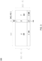
- FIG. 3 is a diagram depicting an example exponent matrix (QC-LDPC exponent matrix) 300, according to one or more embodiments.
- a parity check matrix H see FIG.
- the generator matrix G may have a size n ⁇ k in binary form (e.g., elements of the generator matrix G are binary values).
- FIG. 4 is a diagram 400 depicting example shifted identity matrices 409, 410, 411, 412, 413, 414, 415, 416 for generating a parity check matrix, according to one or more embodiments.
- Any other integer value d in [1,z-1] may correspond (or map) to a matrix cyclically right shifted from I(z) (e.g., matrices 411, 412, 413, 414, 415, 416).
- FIG. 5 is a diagram depicting an example parity check matrix 500, according to one or more embodiments.
- an encoder e.g., encoder 130
- can produce codewords using a generator matrix e.g., using Equation 2).
- an encoder e.g., encoder 130
- a parity check matrix H is obtained (e.g., using a codebook)
- the parity check matrix H (e.g., parity check matrix 500) may have sub-matrices A 510, B 512, C 516, D 518, T 514, E 520.
- An upper area O 515 of the sub-matrix T 514 may correspond to an area in which the matrix contains all zeroes, and the other areas (e.g., grey area in FIG. 5 ) may represent locations that can contain ones.
- the size of the parity check matrix 500 may be m ⁇ n where the size of the sub-matrix D 518 is g ⁇ g, and the size of the sub-matrix T is (m-g)x(m-g).
- the encoder can obtain a codeword c using Equation 10, Equation 11, Equation 12 and Equation 13.
- the code can be directly used in an existing modulation of 64-QAM in the IEEE 802.11be and potentially in combination with more combinations of QAM sizes in the IEEE 802.bn.
- BPSK binary phase-shift keying
- BPSK quadrature phase-shift keying
- 16-QAM 64-QAM
- 256-QAM 256-QAM
- 1024-QAM 1024-QAM
- 4096-QAM as seen in standards such as IEEE 802.11be or IEEE 802.11bn.
- RU OFDMA resource units
- DRU distributed RU
- MRU punctured RUs
- LDPC codes with a block length of 3888 bits (2x1944) can deliver considerable performance improvements in various communication scenarios in ultra high reliability (UHR), while maintaining manageable complexity. Performance comparisons are conducted between these codes and LDPC codes specified in the IEEE 802.11be standards, as well as recently proposed codes with a block length of 4x1944. Results of the performance comparisons show demonstrable gains across the board (e.g., channels, PHY bandwidth, MIMO, modulation coding scheme (MCS), Transmit Beamforming).
- LDPC codes with a block length of 3888 bits can provides 0.5-1.0dB gains over the present 802.11 LDPC codes, depending on channel conditions.
- LDPC codes with a block length of 4x1944 bits can provide additional 0.0-0.5 dB gain, depending on channel conditions.
- BICM bit-interleaved coded modulation
- AWGN additive white Gaussian noise
- QAM Quadrature Amplitude Modulation
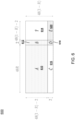
- FIG. 6 is a diagram depicting an example exponent matrix (QC-LDPC exponent matrix) 600, according to one or more embodiments.
- the generator matrix G may have a size n ⁇ k in binary form (e.g., elements of the generator matrix G are binary values).
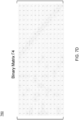
- FIG. 7A is a diagram 700 depicting an example binary matrix ⁇ 1 having a size (dimension) of (12 ⁇ 24), according to one or more embodiments.
- the system can determine (e.g., calculate, compute, obtain) a new parity check matrix H ⁇ by performing Khatri-Rao lifting with the base parity check matrix H and the binary matrix ⁇ 1 using Equation 15.
- FIGS. 7D are diagrams 720, 740, 760 depicting example binary matrices ⁇ 2, ⁇ 3, ⁇ 4, respectively, which have the same size (dimension) as the binary matrix ⁇ 1 but have different entries from the binary matrix ⁇ 1, according to one or more embodiments.
- FIG. 8B , FIG. 8C , FIG. 8D are diagrams 820, 840, 860 depicting example exponent matrices constructed as a result of performing Khatri-Rao lifting using the base parity check matrix H and the binary matrices ⁇ 2, ⁇ 3, ⁇ 4, respectively.
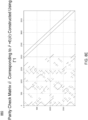
- the new parity check matrix H ⁇ corresponding to the exponent matrix ⁇ E( H ⁇ ) shown in FIG. 8A and the binary matrix ⁇ 1 shown in FIG.
- each black dot/line may represent a value 1 and each empty space may represent a value 0.
- FIG. 9 is a diagram 900 depicting an example implementation (a program source code in a programming language) of generating a new parity check matrix using a binary matrix ⁇ , according to one or more embodiments.
- the program source code in FIG. 9 includes line 1 to line 12..
- the program source code shown in FIG. 9 includes line 1 to line 12.
- the system can derive one or more matrices ⁇ using multiple levels of optimizations by exploiting a combination of graph theoretic constraints (e.g., the number of shortest loops/cycles in a protograph) and simulations.
- the system can calculate the number of shortest loop in a protograph corresponding to a new parity check matrix based on a ⁇ matrix and then perform simulations (e.g., packet error rates) on the new parity check matrix, to evaluate the performance/quality of the ⁇ matrix.
- a "protograph” may refer to a bipartite graph having two disjoint and independent vertex sets (e.g., a set of left vertexes indicated by circles and a set of right vertexes indicated by rectangles in the protograph 1100 shown in FIG. 11A ) to represent a matrix (e.g., parity check matrix).
- the system can apply some graph theoretic constraints to choose/select better ⁇ matrices that can eliminate or reduce short cycles in the protograph, or delete problematic nodes (e.g., trapping sets) which cause the iterative decoding performance to get stuck (jammed, trapped).
- the cycles in a protograph generated using a ⁇ matrix may be weighted in the descending order of degrees of the cycles to evaluate the matrix ⁇ .
- the system can shortlist a plurality of candidate ⁇ matrices, perform simulations (e.g., PER simulations or codeword simulations) on respective parity check matrices generated using plurality of candidate ⁇ matrices, and select (identify, choose, determine) from the shortlisted (candidate) ⁇ matrices, one or more "optimal" ⁇ matrix (e.g., optimal in terms of satisfying graph theoretic constraints and/or simulation constraints (e.g., above a threshold).
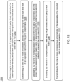
- FIG. 10 is a flow diagram showing a process 1000 for determining one or more binary matrices ⁇ , according to one or more embodiments.
- a system can perform the process 1000 to derive (generate, determine, obtain) one or more (optimal) binary matrices ⁇ to use the derived matrices in generating a new parity check matrix H ⁇ (using Khatri-Rao lifting).
- the process 1000 is performed by one or more processors of an apparatus (e.g., an encoder 130 or a processor 2010 of a communication system 105, or a decoder 160 or a processor 2010 of a communication system 108).
- the process 1000 is performed by other entities (e.g., a computing system other than the system 105 or the system 108).
- the process1000 includes more, fewer, or different steps than shown in FIG. 10 .
- the H1 matrix may correspond to a protograph 1100 and a different graph representation 1110 of the protograph 1100.
- the protograph 1100 and the graph 1110) may include 3*5 check nodes 1-15 (indicated by rectangles) and 4*5 variable nodes 16-35 (indicated by circles).
- the system may perform (apply, compute, calculate) Khatri-Rao lifting to the base parity check matrix H1 using the ⁇ 1 matrix initialized at step 1002, to generate (obtain, calculate, compute) a new parity check matrix H2 as a new QC-LDPC code.
- E H2 ⁇ 1 ⁇ 1 ⁇ 1 2 ⁇ 1 3 ⁇ 1 ⁇ 1 ⁇ 1 ⁇ 1 2 ⁇ 1 3 ⁇ 1 ⁇ 1 ⁇ 1 ⁇ 1 0 3 ⁇ 1 ⁇ 1 1 ⁇ 1 1 0 ⁇ 1 ⁇ 1 3 1 ⁇ 1 1 ⁇ 1 2 ⁇ 1 ⁇ 1 0 ⁇ 1 ⁇ 1 ⁇ 1 3 1 ⁇ 1 1 ⁇ 1 2 ⁇ 1 ⁇ 1 0 ⁇ 1 ⁇ 1 ⁇ 1 2 ⁇ 1 ⁇ 1 ⁇ 1 0 ⁇ 1 ⁇ 1 ⁇ 1 ⁇ 1 0 ⁇ 1 ⁇ 1 ⁇ 1
- the H2 matrix may correspond to a protograph 1120 and a different graph representation 1130 of the protograph 1100.
- the protograph 1120 (and the graph 1130) may include 6*5 check nodes 1-30 (indicated by rectangles) and 8*5 variable nodes 31-70 (indicated by circles).
- the system may determine (check) whether the size (length) of shortest cycle (loop) in the graph corresponding to the H2 matrix ⁇ 6.
- the system may discard the ⁇ matrix.
- the system may add the current ⁇ matrix (e.g., ⁇ 1) to a shortlist of candidate gamma matrices.
- the system may proceed to step 1004 and perform (apply, compute, calculate) Khatri-Rao lifting to the base parity check matrix H1 using the ⁇ 2 matrix updated/changed at step 1014, to generate (obtain, calculate, compute) a new parity check matrix H2' as a new QC-LDPC code.
- E H2 ′ ⁇ 1 ⁇ 1 ⁇ 1 2 ⁇ 1 3 ⁇ 1 ⁇ 1 ⁇ 1 2 ⁇ 1 3 ⁇ 1 ⁇ 1 ⁇ 1 ⁇ 1 0 3 ⁇ 1 ⁇ 1 1 ⁇ 1 1 0 ⁇ 1 ⁇ 1 3 1 ⁇ 1 1 ⁇ 1 2 ⁇ 1 ⁇ 1 ⁇ 1 0 ⁇ 1 ⁇ 1 3 1 ⁇ 1 1 ⁇ 1 2 ⁇ 1 ⁇ 1 ⁇ 1 0 ⁇ 1 ⁇ 1 ⁇ 1 2 ⁇ 1 0 ⁇ 1 ⁇ 1 ⁇ 1 ⁇ 1 ⁇ 1 ⁇ 1 ⁇ 1 ⁇ 1
- the H2' matrix may correspond to a protograph 1140 and a different graph representation 1150 of the protograph 1140.
- the protograph 1140 (and the graph 1150) may include 6*5 check nodes 1-30 (indicated by rectangles) and 8*5 variable nodes 31-70 (indicated by circles).
- the system may add the current ⁇ matrix (e.g., ⁇ 2) to the shortlist of candidate gamma matrices.
- the system may perform one or more simulations (e.g., PER simulation or codeword simulation) on candidate ⁇ matrices in the shortlist.
- the system may determine that the number of candidate ⁇ matrices in the shortlist reaches a threshold (e.g., 10), and perform the simulations.
- the system may determine that the number of iterations (e.g., iterations over steps 1004 to 1012) reaches a threshold (e.g., 100), and perform the simulations.
- the system may select (determine, choose) one or more ⁇ matrices as "optimal" ⁇ matrices from the shortlist based on results of the simulations.
- the system may select one or more ⁇ matrices that satisfy a simulation constraint (e.g., average PER is less than a threshold).
- FIG. 12 is a flow diagram showing a process 1200 for encoding data using an LDPC code, in accordance with an embodiment.
- the process 1200 is performed by one or more processors of an apparatus (e.g. communication system 105, encoder 130, or processor 2010).
- the process 1200 is performed by other entities.
- the process 1200 includes more, fewer, or different steps than shown in FIG. 12 .
- a first parity check matrix e.g., base parity check matrix H
- QC-LDPC quasi-cyclic-low-density parity-check
- the one or more processors may determine a binary matrix (e.g., binary matrix ⁇ or ⁇ matrix) having the same size as a size of an exponent matrix E(H) of the first parity check matrix.
- the one or more processors may be configured to determine a plurality of sub-matrices of the binary matrix (e.g., using Equation 16), each sub-matrix being a power of an exchange matrix of order 2 (e.g., matrix J(2)).
- the one or more processors may be configured to randomize non-zero values of the binary matrix such that the binary matrix maintains to have full rank.
- a second parity check matrix e.g., a new parity check matrix H
- the first code block size may be 1944 bits
- the second code block size may be 3888 bits.
- Each element of the exponent matrix may correspond to a cyclic shift value of an identity matrix.
- a size of the identity matrix is z x z
- the cyclic shift value d is an integer such that -1 ⁇ d ⁇ z, where z is an integer representing a lifting size of the QC-LDPC code.
- the cyclic shift value -1 may represent a null matrix of the identity matrix (see matrix 412 in FIG. 4 ).
- the one or more processors may be configured to determine a first exponent matrix of the first parity check matrix, determine a Khatri-Rao product of the first exponent matrix and the binary matrix (e.g., using Equation 16), and determine, based on a result of the Khatri-Rao product, a second exponent matrix of the second parity check matrix (e.g., using Equation 14).
- the one or more processors may be configured to generate the second parity check matrix such that the second parity check matrix includes, as an element corresponding to each element of the second exponent matrix, the generated shifted identity matrix (see Equation 8).
- the one or more processors may encode data using the generated second parity check matrix (e.g., using Equation 10, Equation 11, Equation 12 and Equation 13).
- the one or more processors may transmit, via a transmitter of the apparatus (e.g., transmitter circuitry 120 of the communication system 105), the encoded data to another apparatus (e.g., communication system 108).
- an apparatus may include a transmitter (e.g., transmitter circuitry 120) and one or more processors (e.g., processor 2010 or baseband circuitry 110).
- the one or more processors may be configured to identify, based on a first parity check matrix (e.g., base parity check matrix H) of a first quasi-cyclic-low-density parity-check (QC-LDPC) code according to a code rate of 1/2, a second parity check matrix (e.g., new parity check matrix H) corresponding to a first exponent matrix (e.g., E( H ⁇ )) including 1152 values for a second QC-LDPC code.
- a first parity check matrix e.g., base parity check matrix H
- QC-LDPC quasi-cyclic-low-density parity-check
- the one or more processors may be configured to encode data using the second parity check matrix.
- the transmitter may be configured to transmit the encoded data to another apparatus (e.g., decoder 160 or processor 2010 of communication system 108).
- the one or more processors may be configured to identify (e.g., from a codebook) the first parity check matrix of the first QC-LDPC code having the code rate of 1/2.
- the one or more processors may be configured to determine a first binary matrix (e.g., ⁇ 1 matrix) having the same dimensions (e.g., m/Z x n/Z if the first parity check matrix has a dimension of (m x n)) as dimensions of an exponent matrix (e.g., E( H )) of the first parity check matrix.
- the one or more processors may be configured to determine a Khatri-Rao product of the first parity check matrix and the first binary matrix (e.g., using Equation 15).
- the one or more processors may be configured to determine, based on a result of the Khatri-Rao product, the second parity check matrix (e.g., new parity check matrix H).
- the one or more processors in determining the first binary matrix, may be configured to determine a second binary matrix having the same dimensions as dimensions of the first binary matrix.
- the one or more processors may be configured to determine the first binary matrix including at least (1) one or more rows of a second binary matrix or (2) one or more columns of the second binary matrix.
- the one or more processors may be configured to determine, based on the result of the Khatri-Rao product, a second exponent matrix having the same dimensions as dimensions of the first exponent matrix.
- the one or more processors may be configured to determine, based on the second exponent matrix, the first exponent matrix.
- the first exponent matrix may have the same entries as the second exponent matrix except one or two entries.
- the one or more processors may be configured to determine, based on the first exponent matrix, the second parity check matrix (e.g., using Equation 8).
- the second binary matrix may include the following set of values: [1 1 1 1 1 1 1 1 1 0 1 0 1 0 0 1 1 1 1 1 1 1 1 0 1 1 1 1 0 1 1 1 1 0 0 1 1 1 1 0 0 1 1 1 1 1 1 01111011011111001111111111111110 1111111111110011111101111101111111111001111110111101 1111011111001111111110111111111111111101111111111 11111111001110111111111111111101111111111 11111111001110111111111101111111111111111111111101111111111 11111111001110111111101111111111111101111111111 11111111001110111111101111111111111100100111111 1 1 1 1 0 0 1 1 1 1 1 1 1 0].
- the second exponent matrix may include the following set of values: [-1 57 -1 -1 -1 -1 -1 -1 -1 -1 -1 -1 -1 50 -1 -1 -1 11 -1 -1 50 -1 -1 -1 79 -1 -1 -1 1 -1 0 -1 -1 -1 -1 -1 -1 -1 -1 -1 -1 -1 -1 -1 -1 -1 -1 -1 -1 -1 -1 -1 -1 -1 -1 57 -1 -1 -1 -1 -1 -1 50 -1 -1 -1 79 -1 -1 -1 1 -1 0 -1 -1 -1 -1 -1 -1 -1 -1 -1 -1 -1 -1 -1 -1 -1 -1 -1 - 1 -1 3 -1 -1 -1 -1 -1 -1 28 -1 -1 0 -1 -1 -1 -1 -1 -1 -1 -1 -1 55 -1 -1 7 -1 -1 -1 -1 -1 -1 0 -1 0
- the one or more processors may be configured to select, from values of the second exponent matrix, at least 1150 values as values of the first exponent matrix.
- the one or more processors may be configured to shift one or two values of the first exponent matrix from one or more corresponding positive values of the second exponent matrix by -1 or +1.
- the one or more corresponding positive values of the second exponent matrix may not be selected as the at least 1150 values.
- the first exponent matrix (e.g., permutation matrix P) may be generated by perturbating one or two values from the second exponent matrix.
- the first matrix may be generated as [-1 56 -1 -1 -1 -1 -1 -1 -1 -1 -1 -1 -1 -1 -1 49 -1 -1 11 -1 -1 50 -1 -1 -1 79 -1 -1 -1 1 -1 0 -1 -1 -1 -1 -1 -1 -1 -1 -1 -1 -1 -1 -1 -1 -1 -1 -1 -1 -1 -1 -1 -1 -1 -1 -1 -1 57 -1 -1 -1 -1 -1 -1 -1 -1 -1 50 -1 -1 -1 11 -1 -1 -1 -1 50 - 1 -1 -179 -1 -1 -1 1 -1 0 -1 -1 -1 -1 -1 -1 -1 -1 -1 -1 -1 -1 -1 -1 -1 -1 -1 -1 -1 -1 -1 -1 -1 -1 -1 -1 -1 -1 -1 -1 -1 -1 -1 -1 -1 -1 -1 -1 -1 -1
- the second binary matrix may include the following set of values: [1 1 1 1 1 1 0 1 0 1 1 1 0 0 1 1 1 1 1 1 1 1 1 1 1 1 1 1 1 1 1 1 1 1 1 0 1 1 1 0 0 1 1 1 1 1 1 0111101101111100111111110011111111111110 0110011111110011111101110101111011111001111100011111 0111011111001111011100110101111111100111111111111111111111111111111111111111111111111111111111111111111111111 1111111100111111011100111111111111110011011011111 1 1 1 1 0 0 1 1 1 1 1 1 1 0].
- the second exponent matrix may include the following set of values: [-1 57 -1 -1 -1 -1 -1 -1 -1 -1 -1 -1 -1 50 -1 -1 11 -1 -1 -1 50 -1 -1 -1 -1 79 -1 1 -1 0 -1 -1 -1 -1 -1 -1 -1 -1 -1 -1 -1 -1 -1 -1 -1 -1 -1 -1 -1 -1 -1 -1 -1 -1 -1 57 -1 -1 -1 -1 -1 50 -1 79 -1 -1 -1 -1 1 -1 0 -1 -1 -1 -1 -1 -1 -1 -1 -1 -1 -1 -1 -1 -1 -1 -1 -1 -1 - 1 -1 -1 28 -1 -1 0 -1 -1 -1 -1 -1 -1 -1 55 -1 -1 7 -1 -1 -1 -1 -1 -1 0 -1 0 0 -1 -1 -1 -1 0 0 -1
- the second binary matrix may include the following set of values: [1 1 1 1 1 1 1 0 1 0 1 1 1 0 0 1 1 1 1 1 1 1 1 1 1 1 1 1 1 1 1 1 1 1 1 1 0 1 1 1 1 0 0 1 1 1 1 1 0111101101111100111111110111101111111110011111110 0111111111110011111101110101111011111001111100011111 0111011111001111011100110101111111100111100111111111111111111 1111111100111111011111111111111111001110011011111 1 1 1 1 0 0 1 1 1 1 1 1 1 0].
- the second exponent matrix may include the following set of values: [-1 57 -1 -1 -1 -1 -1 -1 -1 -1 -1 -1 -1 50 -1 -1 11 -1 -1 -1 50 -1 -1 -1 -1 79 -1 -1 1 -1 0 -1 -1 -1 -1 -1 -1 -1 -1 -1 -1 -1 -1 -1 -1 -1 -1 -1 -1 -1 -1 -1 -1 -1 -1 -1 -1 57 -1 -1 -1 -1 -1 - 1 - 1 11 - 1 - 1 - 1 50 -1 79 -1 -1 -1 -1 1 -1 0 -1 -1 -1 -1 -1 -1 -1 -1 -1 -1 -1 -1 -1 -1 -1 -1 -1 -1 -1 -1 - 1 -1 -1 3 -1 -1 -1 -1 28 -1 -1 -1 0 -1 -1 -1 -1 -1 -1 -1 -1 55 -1
- the one or more processors may be configured to permute (1) two or more rows of the second binary matrix or (2) two or more columns of the second binary matrix.
- the first binary matrix may correspond to a binary matrix in which a first row and a second row of the second binary matrix are permuted.
- the one or more processors may be configured to determine a resulting binary matrix of the permuting as the first binary matrix.
- the first binary matrix may be determined such that the first binary matrix maintains to have full rank.
- the H ⁇ matrix may be generated by (right) multiplying the matrix product H ⁇ x ⁇ by an inverse matrix of the first exponent matrix (e.g., ⁇ -1 ).
- an apparatus may include a receiver (e.g., receiver circuitry 140) configured to receive encoded data (e.g., from another apparatus such as communication system 105), and one or more processors (e.g., processor 2010).
- a receiver e.g., receiver circuitry 140
- processors e.g., processor 2010
- the one or more processors may be configured to identify (e.g., from a codebook), based on a first parity check matrix (e.g., base parity check matrix H) of a first quasi-cyclic-low-density parity-check (QC-LDPC) code according to a code rate of 1/2, a second parity check matrix (e.g., new parity check matrix H ⁇ ) corresponding to a first exponent matrix including 1152 values for a second QC-LDPC code.
- the one or more processors may be configured to decode the received encoded data using the second binary parity check matrix (e.g., new parity check matrix H ⁇ ).
- the encoded data e.g., codeword c
- Equation 1 Equation 1
- Equations 10-13 Equation 10-13
- the first exponent matrix may include at least 1150 values selected from a second exponent matrix having the same dimensions as dimensions of the first exponent matrix (e.g., m/Z x n/Z if the first parity check matrix has a dimension of (m x n)).
- the second exponent matrix may include the following set of values: [-1 57 -1 -1 -1 -1 -1 -1 -1 -1 -1 -1 50 -1 -1 -1 11 -1 -1 50 -1 -1 -1 79 -1 -1 -1 1 -1 0 -1 -1 -1 -1 -1 -1 -1 -1 -1 -1 -1 -1 -1 -1 -1 -1 -1 -1 -1 -1 -1 -1 -1 -1 57 -1 -1 -1 -1 -1 -1 -1 -1 50 -1 -1 -1 - 79 -1 - 1 1 -1 0 -1 -1 -1 -1 -1 -1 -1 -1 -1 -1 -1 -1 -1 -1 -1 -1 -1 -1 -1 -1 -1 -1 -1 -1 -1 -1 -1 -1 -1 -1 -1 -1 -1 -1 -1 -1 -1 -1 -1 -1 -1 -1 -1 -1 -1 -1 -1 -1 -1
- the first exponent matrix may include one or two values shifted from one or more corresponding positive values of the second exponent matrix by -1 or +1.
- the one or more corresponding positive values of the second exponent matrix may not be selected as the at least 1150 values.
- the first exponent matrix (e.g., permutation matrix ⁇ ) may be generated by perturbating one or two values from the second exponent matrix.
- the first matrix may be generated as [-1 56 -1 -1 -1 -1 -1 -1 -1 -1 -1 -1 -1 -1 49 -1 -1 11-1-1 50 -1 -1 -1 79 -1 -1 -1 1 -1 0 -1 -1 -1 -1 -1 -1 -1 -1 -1 -1 -1 -1 -1 -1 -1 -1 -1 -1 -1 -1 -1 -1 -1 -1 -1 -1 -1 57 -1 - 1 -1 -1 -1 -1 -1 50 -1 -1 -1 -1 11 -1 -1 -1 -1 50 -1 -1 -1 79 -1 -1 -1 1 -1 0 -1 -1 -1 -1 -1 -1 -1 -1 -1 -1 -1 -1 -1 -1 -1 -1 - 1 -1 -1 -1 -1 -1 -1 -1 -1 -1 -1 -1 -1 -1 -1 3 -1 -1 -1 -1 -1 -1 28 -1 -1 0
- the second exponent matrix may include the following set of values: [-1 57 -1 -1 -1 -1 -1 -1 -1 -1 -1 -1 -1 50 -1 -1 11 -1 -1 -1 50 -1 -1 -1 -1 79 -1 -1 1 -1 0 -1 -1 -1 -1 -1 -1 -1 -1 -1 -1 -1 -1 -1 -1 -1 -1 -1 -1 -1 -1 -1 -1 -1 -1 -1 -1 57 -1 -1 -1 -1 -1 -1 -1 -1 50 -1 -1 -1 -1 11 -1 -1 -1 50 -1 79 -1 -1 -1 -1 1 -1 0 -1 -1 -1 -1 -1 -1 -1 -1 -1 -1 -1 -1 -1 -1 -1 -1 -1 -1 -1 -1 -1 -1 -1 -1 -1 -1 -1 -1 -1 -1 -1 -1 -1 -1 -1 -1 -1 -1 -1
- the second exponent matrix may include the following set of values: [-1 57 -1 -1 -1 -1 -1 -1 -1 -1 -1 -1 -1 50 -1 -1 11 -1 -1 -1 50 -1 -1 -1 -1 79 -1 -1 1 -1 0 -1 -1 -1 -1 -1 -1 -1 -1 -1 -1 -1 -1 -1 -1 -1 -1 -1 -1 -1 -1 -1 -1 -1 -1 -1 -1 57 -1 -1 -1 -1 -1 -1 -1 -1 50 -1 -1 -1 -1 11 -1 -1 -1 50 -1 79 -1 -1 -1 -1 1 -1 0 -1 -1 -1 -1 -1 -1 -1 -1 -1 -1 -1 -1 -1 -1 -1 -1 -1 -1 -1 -1 -1 -1 -1 -1 -1 -1 -1 -1 -1 -1 -1 -1 -1 -1 -1 -1 -1 -1 -1
- the one or more processors may be configured to identify (e.g., from a codebook) a third binary parity check matrix in which one or more rows or one or more columns of the second binary parity check matrix are permuted, the third binary parity check matrix having the same dimensions as dimensions of the first binary parity check matrix.
- the third binary parity check matrix may correspond to a binary parity check matrix in which a first row and a second row of the second binary parity check matrix are permuted.
- the one or more processors may be further configured to decode the received encoded data using the third binary parity check matrix.
- the one or more processors may be configured to identify a fourth binary parity check matrix corresponding to a third exponent matrix in which one or more rows or one or more columns of the first exponent matrix are permuted.
- the third exponent matrix may correspond to an exponent matrix in which a first row and a second row of the first exponent matrix are permuted.
- the third exponent matrix may have the same dimensions as dimensions of the first exponent matrix.
- the one or more processors may be configured to decode the received encoded data using the fourth binary parity check matrix.
- FIG. 13 is a flow diagram showing a process for encoding data and/or decoding data using an LDPC code, in accordance with an embodiment.
- FIG. 13 is a flow diagram showing a process 1300 for encoding data using an LDPC code, in accordance with an embodiment.
- the process 1300 is performed by one or more processors of a first device (e.g. encoder 130 or processor 2010 of communication system 105) or by one or more processors of a second device (e.g., decoder 160 or processor 2010 of communication system 108).
- the process 1300 is performed by other entities (e.g., a computing system other than the communication system 105 or 108).
- the process 1300 includes more, fewer, or different steps than shown in FIG. 13 .
- the first device may identify, based on a first parity check matrix (e.g., base parity check matrix H) of a first quasi-cyclic-low-density parity-check (QC-LDPC) code according to a code rate of 1/2, a second parity check matrix (e.g., new parity check matrix H ⁇ ) corresponding to a first exponent matrix (e.g., E( H ⁇ )) including 1152 values for a second QC-LDPC code.
- the first parity check matrix of the first QC-LDPC code having the code rate of 1/2 may be identified (e.g., from a codebook) by the first device or another device other than the first device. If the device other than the first device identifies the first parity check matrix, that device may transmit the first parity check matrix to the first device.
- a first binary matrix having the same dimensions e.g., m/Z x n/Z if the first parity check matrix has a dimension of (m x n)
- a Khatri-Rao product of the first parity check matrix and the first binary matrix may be determined (e.g., using Equation 15).
- the second parity check matrix (e.g., new parity check matrix H ⁇ ) may be determined based on a result of the Khatri-Rao product.
- the first binary matrix may be determined by the following steps: (i) determining a second binary matrix having the same dimensions as dimensions of the first binary matrix; and (ii) determining the first binary matrix including at least (1) one or more rows of a second binary matrix or (2) one or more columns of the second binary matrix.
- the second parity check matrix may be determined by the following steps: (i) determining, based on a result of the Khatri-Rao product, a second exponent matrix having the same dimensions as dimensions of the first exponent matrix, (ii) determining, based on the second exponent matrix, the first exponent matrix; and (iii) determining, based on the first exponent matrix, the second parity check matrix (e.g., using Equation 8).
- the second binary matrix may include the following set of values: [1 1 1 1 1 1 0 1 01 1 1 0 0 1 1 1 1 1 1 1 1 1 1 1 1 1 1 1 1 01 1 1 1 0 0 1 1 1 1 1 1 1 0111101101111100111111110011111111111110 0110011111110011111101110101111011111001111100011111 0111011111001111011100110101111111100111110111111111111111111111111111111111111111111111111111111111111111111111111111111111111111 1111111100111111011100111111111110011011011111 1 1 1 1 0 0 1 1 1 1 1 1 1 0].
- the second exponent matrix may include the following set of values: [-1 57 -1 -1 -1 -1 -1 -1 -1 -1 -1 -1 -1 50 -1 -1 11 -1 -1 -1 50 -1 -1 -1 -1 79 -1 1 -1 0 -1 -1 -1 -1 -1 -1 -1 -1 -1 -1 -1 -1 -1 -1 -1 -1 -1 -1 -1 -1 -1 -1 -1 -1 -1 57 -1 -1 -1 -1 -1 50 -1 79 -1 -1 -1 -1 1 -1 0 -1 -1 -1 -1 -1 -1 -1 -1 -1 -1 -1 -1 -1 -1 -1 -1 -1 -1 - 1 -1 -1 28 -1 -1 0 -1 -1 -1 -1 -1 -1 -1 55 -1 -1 7 -1 -1 -1 -1 -1 -1 0 -1 0 0 -1 -1 -1 -1 0 0 -1
- the first exponent matrix may be determined by the following steps: (i) selecting, from values of the second exponent matrix, at least 1150 values as values of the first exponent matrix; and (ii) shifting one or two values of the first exponent matrix from one or more corresponding positive values of the second exponent matrix by -1 or + 1; (iii) determining a resulting matrix of the shifting as the first exponent matrix.
- the one or more corresponding positive values of the second exponent matrix may not be selected as the at least 1150 values.
- the first exponent matrix (e.g., permutation matrix ⁇ ) may be generated by perturbating one or two values from the second exponent matrix.
- the first matrix may be generated as [-1 56 -1 -1 -1 -1 -1 -1 -1 -1 -1 -1 -1 -1 49 -1 -1 11 -1 -1 50 -1 -1 -1 79 -1 -1 -1 1 -1 0 -1 -1 -1 -1 -1 -1 -1 -1 -1 -1 -1 -1 -1 -1 -1 -1 -1 -1 -1 -1 -1 -1 -1 -1 -1 -1 -1 57 -1 -1 -1 -1 -1 -1 -1 -1 50 -1 - 1 11 -1 -1 -1 -1 50 -1 -1 -1 79 -1 -1 -1 1 -1 0 -1 -1 -1 -1 -1 -1 -1 -1 -1 -1 -1 -1 -1 -1 -1 -1 -1 -1 -1 - 1 3 -1 -1 -1 -1 -1 28 -1 -1 0 -1 -1 -1 -1 -1 -1 -1 -1 -1 -1 -1 -1
- the second binary matrix may include the following set of values: [1 1 1 1 1 1 0 1 0 1 1 1 0 0 1 1 1 1 1 1 1 1 1 1 1 1 1 1 1 1 1 1 1 1 1 0 1 1 1 0 0 1 1 1 1 1 1 0111101101111100111111110011111111111110 0110011111110011111101110101111011111001111100011111 0111011111001111011100110101111111100111111111111111111111111111111111111111111111111111111111111111111111111 1111111100111111011100111111111111110011011011111 1 1 1 1 0 0 1 1 1 1 1 1 1 0].
- the second exponent matrix may include the following set of values: [-1 57 -1 -1 -1 -1 -1 -1 -1 -1 -1 -1 -1 50 -1 -1 -1 11 -1 -1 50 -1 -1 -1 79 -1 -1 -1 1 -1 0 -1 -1 -1 -1 -1 -1 -1 -1 -1 -1 -1 -1 -1 -1 -1 -1 -1 -1 -1 -1 -1 -1 -1 -1 57 -1 -1 -1 -1 -1 -1 50 -1 -1 -1 79 -1 -1 -1 1 -1 0 -1 -1 -1 -1 -1 -1 -1 -1 -1 -1 -1 -1 -1 -1 -1 -1 -1 - 1 -1 3 -1 -1 -1 -1 -1 -1 28 -1 -1 0 -1 -1 -1 -1 -1 -1 -1 -1 -1 55 -1 -1 7 -1 -1 -1 -1 -1 -1 0 -1 0
- the second binary matrix may include the following set of values: [1 1 1 1 1 1 1 0 1 0 1 1 1 0 0 1 1 1 1 1 1 1 1 1 1 1 1 1 1 1 1 1 1 1 1 1 0 1 1 1 1 0 0 1 1 1 1 1 0111101101111100111111110111101111111110011111110 0111111111110011111101110101111011111001111100011111 0111011111001111011100110101111111100111100111111111111111111 1111111100111111011111111111111111001110011011111 1 1 1 1 0 0 1 1 1 1 1 1 1 0].
- the second exponent matrix may include the following set of values: [-1 57 -1 -1 -1 -1 -1 -1 -1 -1 -1 -1 -1 50 -1 -1 11 -1 -1 -1 50 -1 -1 -1 -1 79 -1 1 -1 0 -1 -1 -1 -1 -1 -1 -1 -1 -1 -1 -1 -1 -1 -1 -1 -1 -1 -1 -1 -1 -1 -1 -1 -1 -1 57 -1 -1 -1 -1 -1 50 -1 79 -1 -1 -1 -1 1 -1 0 -1 -1 -1 -1 -1 -1 -1 -1 -1 -1 -1 -1 -1 -1 -1 -1 -1 -1 - 1 -1 -1 28 -1 -1 0 -1 -1 -1 -1 -1 -1 -1 55 -1 -1 7 -1 -1 -1 -1 -1 -1 0 -1 0 0 -1 -1 -1 -1 0 0 -1
- the first binary matrix may be determined by the following steps: (i) permuting (1) two or more rows of the second binary matrix or (2) two or more columns of the second binary matrix; and (ii) determining a resulting binary matrix of the permuting as the first binary matrix.
- the first binary matrix may correspond to a binary matrix in which a first row and a second row of the second binary matrix are permuted.
- the first binary matrix may be determined such that the first binary matrix maintains to have full rank.
- the first device may encode data using the second parity check matrix.
- the first device may transmit the encoded data to another apparatus (e.g., communication system 108).
- the second device may identify (e.g., from a codebook) the second binary parity check matrix (e.g., new parity check matrix H).
- the second device may receive, from the first device (e.g., communication system 105), the encoded data.
- the second device may decode the encoded data using the second binary parity check matrix.
- the second device may identify (e.g., from a codebook) a third binary parity check matrix in which one or more rows or one or more columns of the second binary parity check matrix are permuted, the third binary parity check matrix having the same dimensions as dimensions of the first binary parity check matrix.
- the third binary parity check matrix may correspond to a binary parity check matrix in which a first row and a second row of the second binary parity check matrix are permuted. the second device may decode the received encoded data using the third binary parity check matrix.
- the second device may be configured to identify a fourth binary parity check matrix corresponding to a third exponent matrix in which one or more rows or one or more columns of the first exponent matrix are permuted.
- the third exponent matrix may correspond to an exponent matrix in which a first row and a second row of the first exponent matrix are permuted.
- the third exponent matrix may have the same dimensions as dimensions of the first exponent matrix.
- the second device may decode the received encoded data using the fourth binary parity check matrix.
- references to "or” may be construed as inclusive so that any terms described using “or” may indicate any of a single, more than one, and all of the described terms. References to at least one of a conjunctive list of terms may be construed as an inclusive OR to indicate any of a single, more than one, and all of the described terms. For example, a reference to "at least one of 'A' and 'B'” can include only 'A', only 'B', as well as both 'A' and 'B'. Such references used in conjunction with “comprising" or other open terminology can include additional items.
- first and second in connection with subsets of transmit spatial streams, sounding frames, response, and devices, for purposes of identifying or differentiating one from another or from others. These terms are not intended to merely relate entities (e.g., a first device and a second device) temporally or according to a sequence, although in some cases, these entities can include such a relationship. Nor do these terms limit the number of possible entities (e.g., STAs, APs, beamformers and/or beamformees) that can operate within a system or environment.
- the systems and methods described above can be provided as one or more computer-readable programs or executable instructions embodied on or in one or more articles of manufacture, e.g., a floppy disk, a hard disk, a CD-ROM, a flash memory card, a PROM, a RAM, a ROM, or a magnetic tape.
- the programs can be implemented in any programming language, such as LISP, PERL, C, C++, C#, or in any byte code language such as JAVA.
- the software programs or executable instructions can be stored on or in one or more articles of manufacture as object code.
Landscapes
- Physics & Mathematics (AREA)
- Mathematical Physics (AREA)
- Probability & Statistics with Applications (AREA)
- Engineering & Computer Science (AREA)
- Theoretical Computer Science (AREA)
- Error Detection And Correction (AREA)
- Lubricants (AREA)
Applications Claiming Priority (5)
| Application Number | Priority Date | Filing Date | Title |
|---|---|---|---|
| US202363610566P | 2023-12-15 | 2023-12-15 | |
| US202363610762P | 2023-12-15 | 2023-12-15 | |
| US202363610859P | 2023-12-15 | 2023-12-15 | |
| US202363610928P | 2023-12-15 | 2023-12-15 | |
| US18/647,663 US12621007B2 (en) | 2024-04-26 | Systems and methods for block-kronecker based low density parity check (LDPC) code with 1/2 code rate |
Publications (1)
| Publication Number | Publication Date |
|---|---|
| EP4572151A1 true EP4572151A1 (de) | 2025-06-18 |
Family
ID=93563049
Family Applications (1)
| Application Number | Title | Priority Date | Filing Date |
|---|---|---|---|
| EP24212855.1A Pending EP4572151A1 (de) | 2023-12-15 | 2024-11-14 | Systeme und verfahren für block-kronecker-basierten low-density parity check (ldpc)-code mit coderate 1/2 und kodeblocklänge von 3888 bits |
Country Status (1)
| Country | Link |
|---|---|
| EP (1) | EP4572151A1 (de) |
Citations (1)
| Publication number | Priority date | Publication date | Assignee | Title |
|---|---|---|---|---|
| EP3540948A1 (de) * | 2017-05-05 | 2019-09-18 | Huawei Technologies Co., Ltd. | Informationsverarbeitungsverfahren und kommunikationsvorrichtung |
-
2024
- 2024-11-14 EP EP24212855.1A patent/EP4572151A1/de active Pending
Patent Citations (1)
| Publication number | Priority date | Publication date | Assignee | Title |
|---|---|---|---|---|
| EP3540948A1 (de) * | 2017-05-05 | 2019-09-18 | Huawei Technologies Co., Ltd. | Informationsverarbeitungsverfahren und kommunikationsvorrichtung |
Non-Patent Citations (4)
| Title |
|---|
| 802.11 WORKING GROUP, vol. 802.11ay drafts, no. D0.2, 9 February 2017 (2017-02-09), pages 1 - 193, XP068137600, Retrieved from the Internet <URL:www.ieee802.org/11/private/Draft_Standards/11ay/Draft P802.11ay_D0.2.pdf> [retrieved on 20170209] * |
| 802.11 WORKING GROUP: "IEEE Std 802.11-2016", 14 December 2016 (2016-12-14) - 7 March 2025 (2025-03-07), pages 3295 - 3295, XP093256916, Retrieved from the Internet <URL:https://ieeexplore.ieee.org/stamp/stamp.jsp?tp=&arnumber=7786995> [retrieved on 20250307] * |
| 802.11 WORKING GROUP: "IEEE Std 802.11-2016", 14 December 2016 (2016-12-14), pages 2450 - 2451, XP093257139, Retrieved from the Internet <URL:https://ieeexplore.ieee.org/stamp/stamp.jsp?tp=&arnumber=7786995&tag> [retrieved on 20250307] * |
| RICHARDSONURBANKE, IEEE TRANSACTIONS ON INFORMATION THEORY, vol. 47, no. 2, February 2001 (2001-02-01) |
Also Published As
| Publication number | Publication date |
|---|---|
| US20250202503A1 (en) | 2025-06-19 |
Similar Documents
| Publication | Publication Date | Title |
|---|---|---|
| JP2019522435A (ja) | Ldpc符号の符号化および復号化のための方法およびシステム | |
| US12556201B2 (en) | System and method for low density parity check (LDPC) code with 1/2 code rate | |
| EP4572153A1 (de) | Systeme und verfahren für block-kronecker-basierten low-density parity check (ldpc)-code mit coderate 3/4 und kodeblocklänge von 3888 bits | |
| EP4572154A1 (de) | Systeme und verfahren für block-kronecker-basierten low-density parity check (ldpc)-code mit coderate 5/6 und kodeblocklänge von 3888 bits | |
| EP4572151A1 (de) | Systeme und verfahren für block-kronecker-basierten low-density parity check (ldpc)-code mit coderate 1/2 und kodeblocklänge von 3888 bits | |
| US12621007B2 (en) | Systems and methods for block-kronecker based low density parity check (LDPC) code with 1/2 code rate | |
| EP4572152A1 (de) | Systeme und verfahren für block-kronecker-basierten low-density parity check (ldpc)-code mit coderate 2/3 und kodeblocklänge von 3888 bits | |
| US12621008B2 (en) | Systems and methods for block-kronecker based low density parity check (LDPC) code with 2/3 code rate | |
| EP4675950A1 (de) | Systeme und verfahren für quasizyklischen low-density parity check (qc-ldpc) code mit 1/2 coderate | |
| EP4675929A1 (de) | Systeme und verfahren für quasizyklischen low-density parity check (qc-ldpc) code mit 1/2 coderate | |
| US20260012199A1 (en) | Systems and methods for quasi-cyclic low density parity check (qc-ldpc) code with 3/4 code rate | |
| US20260012204A1 (en) | Systems and methods for quasi-cyclic low density parity check (qc-ldpc) code with 3/4 code rate | |
| US20260012201A1 (en) | Systems and methods for quasi-cyclic low density parity check (qc-ldpc) code with 5/6 code rate | |
| US20260012198A1 (en) | Systems and methods for quasi-cyclic low density parity check (qc-ldpc) code with 2/3 code rate | |
| US20260012202A1 (en) | Systems and methods for quasi-cyclic low density parity check (qc-ldpc) code with 1/2 code rate | |
| US20260012283A1 (en) | Systems and methods for quasi-cyclic low density parity check (qc-ldpc) code with 1/2 code rate | |
| US20260012203A1 (en) | Systems and methods for quasi-cyclic low density parity check (qc-ldpc) code with 2/3 code rate | |
| US20260012200A1 (en) | Systems and methods for quasi-cyclic low density parity check (qc-ldpc) code with 5/6 code rate | |
| US12549201B2 (en) | System and method for low density parity check (LDPC) code with 3/4 code rate | |
| US20250047305A1 (en) | System and method for low density parity check (ldpc) code with 5/6 code rate | |
| US20250047307A1 (en) | System and method for low density parity check (ldpc) code with 2/3 code rate | |
| US20250274218A1 (en) | Multi-rate low-density parity check (ldpc) codes | |
| CN120165702A (zh) | 用于具有1/2码率的基于块克罗内克的低密度奇偶校验(ldpc)码的系统及方法 | |
| CN120165703A (zh) | 用于具有2/3码率的基于块克罗内克的低密度奇偶校验(ldpc)码的系统及方法 | |
| CN120165700A (zh) | 用于具有3/4码率的基于块克罗内克的低密度奇偶校验(ldpc)码的系统及方法 |
Legal Events
| Date | Code | Title | Description |
|---|---|---|---|
| PUAI | Public reference made under article 153(3) epc to a published international application that has entered the european phase |
Free format text: ORIGINAL CODE: 0009012 |
|
| STAA | Information on the status of an ep patent application or granted ep patent |
Free format text: STATUS: THE APPLICATION HAS BEEN PUBLISHED |
|
| AK | Designated contracting states |
Kind code of ref document: A1 Designated state(s): AL AT BE BG CH CY CZ DE DK EE ES FI FR GB GR HR HU IE IS IT LI LT LU LV MC ME MK MT NL NO PL PT RO RS SE SI SK SM TR |
|
| STAA | Information on the status of an ep patent application or granted ep patent |
Free format text: STATUS: REQUEST FOR EXAMINATION WAS MADE |
|
| 17P | Request for examination filed |
Effective date: 20251217 |