EP4572219A1 - Verfahren zur durchführung einer kommunikation in einem drahtloskommunikationssystem und vorrichtung dafür - Google Patents
Verfahren zur durchführung einer kommunikation in einem drahtloskommunikationssystem und vorrichtung dafür Download PDFInfo
- Publication number
- EP4572219A1 EP4572219A1 EP23852842.6A EP23852842A EP4572219A1 EP 4572219 A1 EP4572219 A1 EP 4572219A1 EP 23852842 A EP23852842 A EP 23852842A EP 4572219 A1 EP4572219 A1 EP 4572219A1
- Authority
- EP
- European Patent Office
- Prior art keywords
- ncr
- fwd
- time resource
- forwarding
- uplink signal
- Prior art date
- Legal status (The legal status is an assumption and is not a legal conclusion. Google has not performed a legal analysis and makes no representation as to the accuracy of the status listed.)
- Pending
Links
Images



Classifications
-
- H—ELECTRICITY
- H04—ELECTRIC COMMUNICATION TECHNIQUE
- H04W—WIRELESS COMMUNICATION NETWORKS
- H04W72/00—Local resource management
- H04W72/50—Allocation or scheduling criteria for wireless resources
- H04W72/56—Allocation or scheduling criteria for wireless resources based on priority criteria
- H04W72/566—Allocation or scheduling criteria for wireless resources based on priority criteria of the information or information source or recipient
- H04W72/569—Allocation or scheduling criteria for wireless resources based on priority criteria of the information or information source or recipient of the traffic information
-
- H—ELECTRICITY
- H04—ELECTRIC COMMUNICATION TECHNIQUE
- H04B—TRANSMISSION
- H04B7/00—Radio transmission systems, i.e. using radiation field
- H04B7/14—Relay systems
- H04B7/15—Active relay systems
- H04B7/155—Ground-based stations
- H04B7/15528—Control of operation parameters of a relay station to exploit the physical medium
-
- H—ELECTRICITY
- H04—ELECTRIC COMMUNICATION TECHNIQUE
- H04B—TRANSMISSION
- H04B7/00—Radio transmission systems, i.e. using radiation field
- H04B7/14—Relay systems
- H04B7/15—Active relay systems
- H04B7/155—Ground-based stations
- H04B7/15528—Control of operation parameters of a relay station to exploit the physical medium
- H04B7/15542—Selecting at relay station its transmit and receive resources
-
- H—ELECTRICITY
- H04—ELECTRIC COMMUNICATION TECHNIQUE
- H04J—MULTIPLEX COMMUNICATION
- H04J3/00—Time-division multiplex systems
- H04J3/16—Time-division multiplex systems in which the time allocation to individual channels within a transmission cycle is variable, e.g. to accommodate varying complexity of signals, to vary number of channels transmitted
-
- H—ELECTRICITY
- H04—ELECTRIC COMMUNICATION TECHNIQUE
- H04L—TRANSMISSION OF DIGITAL INFORMATION, e.g. TELEGRAPHIC COMMUNICATION
- H04L5/00—Arrangements affording multiple use of the transmission path
-
- H—ELECTRICITY
- H04—ELECTRIC COMMUNICATION TECHNIQUE
- H04L—TRANSMISSION OF DIGITAL INFORMATION, e.g. TELEGRAPHIC COMMUNICATION
- H04L5/00—Arrangements affording multiple use of the transmission path
- H04L5/003—Arrangements for allocating sub-channels of the transmission path
- H04L5/0044—Allocation of payload; Allocation of data channels, e.g. PDSCH or PUSCH
-
- H—ELECTRICITY
- H04—ELECTRIC COMMUNICATION TECHNIQUE
- H04L—TRANSMISSION OF DIGITAL INFORMATION, e.g. TELEGRAPHIC COMMUNICATION
- H04L5/00—Arrangements affording multiple use of the transmission path
- H04L5/14—Two-way operation using the same type of signal, i.e. duplex
-
- H—ELECTRICITY
- H04—ELECTRIC COMMUNICATION TECHNIQUE
- H04W—WIRELESS COMMUNICATION NETWORKS
- H04W72/00—Local resource management
- H04W72/04—Wireless resource allocation
- H04W72/044—Wireless resource allocation based on the type of the allocated resource
- H04W72/0446—Resources in time domain, e.g. slots or frames
-
- H—ELECTRICITY
- H04—ELECTRIC COMMUNICATION TECHNIQUE
- H04W—WIRELESS COMMUNICATION NETWORKS
- H04W72/00—Local resource management
- H04W72/12—Wireless traffic scheduling
- H04W72/1263—Mapping of traffic onto schedule, e.g. scheduled allocation or multiplexing of flows
- H04W72/1268—Mapping of traffic onto schedule, e.g. scheduled allocation or multiplexing of flows of uplink data flows
-
- H—ELECTRICITY
- H04—ELECTRIC COMMUNICATION TECHNIQUE
- H04W—WIRELESS COMMUNICATION NETWORKS
- H04W72/00—Local resource management
- H04W72/20—Control channels or signalling for resource management
- H04W72/21—Control channels or signalling for resource management in the uplink direction of a wireless link, i.e. towards the network
-
- H—ELECTRICITY
- H04—ELECTRIC COMMUNICATION TECHNIQUE
- H04W—WIRELESS COMMUNICATION NETWORKS
- H04W72/00—Local resource management
- H04W72/20—Control channels or signalling for resource management
- H04W72/23—Control channels or signalling for resource management in the downlink direction of a wireless link, i.e. towards a terminal
- H04W72/231—Control channels or signalling for resource management in the downlink direction of a wireless link, i.e. towards a terminal the control data signalling from the layers above the physical layer, e.g. RRC or MAC-CE signalling
-
- H—ELECTRICITY
- H04—ELECTRIC COMMUNICATION TECHNIQUE
- H04W—WIRELESS COMMUNICATION NETWORKS
- H04W72/00—Local resource management
- H04W72/20—Control channels or signalling for resource management
- H04W72/23—Control channels or signalling for resource management in the downlink direction of a wireless link, i.e. towards a terminal
- H04W72/232—Control channels or signalling for resource management in the downlink direction of a wireless link, i.e. towards a terminal the control data signalling from the physical layer, e.g. DCI signalling
-
- H—ELECTRICITY
- H04—ELECTRIC COMMUNICATION TECHNIQUE
- H04W—WIRELESS COMMUNICATION NETWORKS
- H04W74/00—Wireless channel access
- H04W74/08—Non-scheduled access, e.g. ALOHA
- H04W74/0833—Random access procedures, e.g. with 4-step access
-
- H—ELECTRICITY
- H04—ELECTRIC COMMUNICATION TECHNIQUE
- H04W—WIRELESS COMMUNICATION NETWORKS
- H04W84/00—Network topologies
- H04W84/02—Hierarchically pre-organised networks, e.g. paging networks, cellular networks, WLAN [Wireless Local Area Network] or WLL [Wireless Local Loop]
- H04W84/04—Large scale networks; Deep hierarchical networks
- H04W84/042—Public Land Mobile systems, e.g. cellular systems
- H04W84/047—Public Land Mobile systems, e.g. cellular systems using dedicated repeater stations
-
- H—ELECTRICITY
- H04—ELECTRIC COMMUNICATION TECHNIQUE
- H04W—WIRELESS COMMUNICATION NETWORKS
- H04W88/00—Devices specially adapted for wireless communication networks, e.g. terminals, base stations or access point devices
- H04W88/08—Access point devices
- H04W88/085—Access point devices with remote components
Definitions
- a method for a device to perform communication in a wireless communication system and a device therefor is a method for a device to perform communication in a wireless communication system and a device therefor.
- Wireless communication systems have been widely deployed to provide various types of communication services such as voice or data.
- a wireless communication system is a multiple access system that supports communication of multiple users by sharing available system resources (a bandwidth, transmission power, etc.).
- multiple access systems include a code division multiple access (CDMA) system, a frequency division multiple access (FDMA) system, a time division multiple access (TDMA) system, an orthogonal frequency division multiple access (OFDMA) system, a single carrier frequency division multiple access (SC-FDMA) system, and a multi carrier frequency division multiple access (MC-FDMA) system.
- CDMA code division multiple access
- FDMA frequency division multiple access
- TDMA time division multiple access
- OFDMA orthogonal frequency division multiple access
- SC-FDMA single carrier frequency division multiple access
- MC-FDMA multi carrier frequency division multiple access
- a next-generation radio access technology in consideration of enhanced mobile broadband communication, massive Machine Type Communication (MTC), and Ultra-Reliable and Low Latency Communication (URLLC) may be referred to as new radio access technology (RAT) or new radio (NR).
- RAT new radio access technology
- NR new radio
- Objects to be achieved are to provide a method and device for efficiently performing time division multiplexing (TDM) between a forwarding operation on a forwarding link and a transmission operation of an uplink signal on a control link.
- TDM time division multiplexing
- a method of performing communication by a device in which a forwarding link for forwarding a signal received from a user equipment (UE) and a control link are formed with a base station (BS) in a wireless communication system including configuring, through the control link, a first time resource on which a forwarding operation on the forwarding link is performed, receiving resource allocation information about a second time resource on which transmission of an uplink signal on the control link is performed, and determining whether to perform transmission of the uplink signal with priority over the forwarding operation on the second time resource overlapping with the first time resource based on a type or payload of the uplink signal.
- transmission of the uplink signal may be performed with priority over the forwarding operation based on the uplink signal including uplink control information (UCI).
- UCI uplink control information
- the device may determine, based on the uplink signal including the UCI, that the forwarding operation on the first time resource overlapping with the second time resource is set to OFF based on the resource allocation information.
- transmission of the UL signal may be dropped based on the uplink signal not including the UCI.
- transmission of the uplink signal is performed with priority over the forwarding operation based on the uplink signal being a dynamic grant physical uplink shared channel (DG PUSCH).
- DG PUSCH dynamic grant physical uplink shared channel
- transmission of the uplink signal may be performed with priority over the forwarding operation based on the uplink signal being a configured grant physical uplink shared channel (CG PUSCH) of Type 1 or Type 2.
- CG PUSCH physical uplink shared channel
- transmission of the uplink signal may be performed with priority over the forwarding operation based on the uplink signal being an uplink signal for a random access channel (RACH) procedure.
- RACH random access channel
- the first time resource may be configured through side control information for control of the forwarding link.
- the forwarding operation on the forwarding link may be skipped on a time resource on transmission of the uplink signal is performed.
- the device may be a network-controlled repeater (NCR).
- NCR network-controlled repeater
- a forwarding link for forwarding a signal received from a user equipment (UE) and a control link are formed with a base station (BS) in a wireless communication system, including a radio frequency (RF) transceiver, and a processor configured to control the RF transceiver.
- the processor configures, through the control link, a first time resource on which a forwarding operation on the forwarding link is performed, receives resource allocation information about a second time resource on which transmission of an uplink signal on the control link is performed, and determines whether to perform transmission of the uplink signal with priority over the forwarding operation on the second time resource overlapping with the first time resource based on a type or payload of the uplink signal.
- a chipset for controlling a device in which a forwarding link for forwarding a signal received from a user equipment (UE) and a control link are formed with a base station (BS) in a wireless communication system, including at least one processor, and at least one memory operatively connected to the at least one processor and configured to cause, when executed, the at least one processor to perform operations.
- BS base station
- the operations include configuring, through the control link, a first time resource on which a forwarding operation on the forwarding link is performed, receiving resource allocation information about a second time resource on which transmission of an uplink signal on the control link is performed, and determining whether to perform transmission of the uplink signal with priority over the forwarding operation on the second time resource overlapping with the first time resource based on a type or payload of the uplink signal.
- TDM between a forwarding operation on a forwarding link and a transmission operation of an uplink signal on a control link is efficiently performed.
- delay in a control operation of a base station for a device is minimized by exceptionally allowing an uplink transmission operation on a control link in a specific situation even in a time interval of a forwarding operation on a forwarding link.
- the wireless communication system is a multiple access system that supports communication with multiple users by sharing available system resources (e.g., bandwidth, transmission power, etc.).
- Examples of the multiple access system include a code division multiple access (CDMA) system, a frequency division multiple access (FDMA) system, a time division multiple access (TDMA) system, an orthogonal frequency division multiple access (OFDMA) system, a single carrier frequency (SC-FDMA) system, a multi carrier frequency division multiple access (MC-FDMA) system, and the like.
- CDMA code division multiple access
- FDMA frequency division multiple access
- TDMA time division multiple access
- OFDMA orthogonal frequency division multiple access
- SC-FDMA single carrier frequency division multiple access
- MC-FDMA multi carrier frequency division multiple access
- a sidelink refers to a communication scheme in which a direct link is established between user equipments (UEs) to directly exchange voice or data between UEs without assistance from a base station (BS).
- UEs user equipments
- BS base station
- the sidelink is being considered as one way to address the burden on the BS caused by rapidly increasing data traffic.
- V2X Vehicle-to-everything refers to a communication technology for exchanging information with other vehicles, pedestrians, and infrastructure-built objects through wired/wireless communication.
- V2X may be divided into four types: vehicle-to-vehicle (V2V), vehicle-to-infrastructure (V2I), vehicle-to-network (V2N), and vehicle-to-pedestrian (V2P).
- V2X communication may be provided through a PC5 interface and/or a Uu interface.
- a next-generation radio access technology in consideration of enhanced mobile broadband communication, massive MTC, and Ultra-Reliable and Low Latency Communication (URLLC) may be referred to as new radio access technology (RAT) or new radio (NR).
- RAT new radio access technology
- NR new radio
- CDMA code division multiple access
- FDMA frequency division multiple access
- TDMA time division multiple access
- OFDMA orthogonal frequency division multiple access
- SC-FDMA single carrier-frequency division multiple access
- CDMA may be implemented as a radio technology such as universal terrestrial radio access (UTRA) or CDMA2000.
- TDMA may be implemented as a radio technology such as global system for mobile communications (GSM)/general packet radio service (GPRS)/Enhanced Data Rates for GSM Evolution (EDGE).
- GSM global system for mobile communications
- GPRS general packet radio service
- EDGE Enhanced Data Rates for GSM Evolution
- OFDMA may be implemented as a radio technology such as IEEE 802.11 (Wi-Fi), IEEE 802.16 (WiMAX), IEEE 802.20, evolved-UTRA (E-UTRA) etc.
- UTRA is a part of universal mobile telecommunications system (UMTS).
- 3GPP LTE is a part of Evolved UMTS (E-UMTS) using E-UTRA.
- 3GPP LTE employs OFDMA for downlink and SC-FDMA for uplink.
- LTE-A is an evolution of 3GPP LTE.
- 3GPP NR New Radio or New Radio Access Technology
- 3GPP LTE/LTE-A/LTE-A pro is an evolved version of 3GPP LTE/LTE-A/LTE-A pro.
- 5G NR is a successor technology of LTE-A, and is a new clean-slate mobile communication system with characteristics such as high performance, low latency, and high availability. 5G NR may utilize all available spectrum resources, from low frequency bands below 1 GHz to intermediate frequency bands from 1 GHz to 10 GHz and high frequency (millimeter wave) bands above 24 GHz.
- LTE-A or 5G NR is mainly described, but the technical spirit of the embodiment(s) is not limited thereto.
- FIG. 1 illustrates the structure of an LTE system to which the present disclosure is applicable. This may also be called an evolved UMTS terrestrial radio access network (E-UTRAN) or LTE/LTE-A system.
- E-UTRAN evolved UMTS terrestrial radio access network
- LTE/LTE-A system LTE/LTE-A system
- the E-UTRAN includes evolved Node Bs (eNBs) 20 which provide a control plane and a user plane to UEs 10.
- a UE 10 may be fixed or mobile, and may also be referred to as a mobile station (MS), user UE (UT), subscriber station (SS), mobile UE (MT), or wireless device.
- An eNB 20 is a fixed station communication with the UE 10 and may also be referred to as a base station (BS), a base transceiver system (BTS), or an access point.
- BS base station
- BTS base transceiver system
- eNBs 20 may be connected to each other via an X2 interface.
- An eNB 20 is connected to an evolved packet core (EPC) 39 via an S1 interface. More specifically, the eNB 20 is connected to a mobility management entity (MME) via an S1-MME interface and to a serving gateway (S-GW) via an S1-U interface.
- EPC evolved packet core
- MME mobility management entity
- S-GW serving gateway
- the EPC 30 includes an MME, an S-GW, and a packet data network-gateway (P-GW).
- the MME has access information or capability information about UEs, which are mainly used for mobility management of the UEs.
- the S-GW is a gateway having the E-UTRAN as an end point
- the P-GW is a gateway having a packet data network (PDN) as an end point.
- PDN packet data network
- the radio protocol stack between a UE and a network may be divided into Layer 1 (L1), Layer 2 (L2) and Layer 3 (L3). These layers are defined in pairs between a UE and an Evolved UTRAN (E-UTRAN), for data transmission via the Uu interface.
- L1 Layer 1
- L2 Layer 2
- L3 Layer 3
- PHY physical
- RRC radio resource control
- FIG. 2 illustrates the structure of a NR system to which the present disclosure is applicable.
- a next generation radio access network may include a next generation Node B (gNB) and/or an eNB, which provides user-plane and control-plane protocol termination to a UE.
- the NG-RAN is shown as including only gNBs, by way of example.
- a gNB and an eNB are connected to each other via an Xn interface.
- the gNB and the eNB are connected to a 5G core network (5GC) via an NG interface.
- 5GC 5G core network
- the gNB and the eNB are connected to an access and mobility management function (AMF) via an NG-C interface and to a user plane function (UPF) via an NG-U interface.
- AMF access and mobility management function
- UPF user plane function
- FIG. 3 illustrates the structure of a NR radio frame to which the present disclosure is applicable.
- a radio frame may be used for UL transmission and DL transmission in NR.
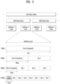
- a radio frame is 10 ms in length, and may be defined by two 5-ms half-frames.
- An HF may include five 1-ms subframes.
- a subframe may be divided into one or more slots, and the number of slots in an SF may be determined according to a subcarrier spacing (SCS).
- SCS subcarrier spacing
- Each slot may include 12 or 14 OFDM(A) symbols according to a cyclic prefix (CP).
- CP cyclic prefix
- each slot may include 14 symbols, whereas in an extended CP (ECP) case, each slot may include 12 symbols.
- a symbol may be an OFDM symbol (or CP-OFDM symbol) or an SC-FDMA symbol (or DFT-s-OFDM symbol).
- Table 1 below lists the number of symbols per slot N slot symb , the number of slots per frame N frame,u slot , and the number of slots per subframe N subframe,u slot according to an SCS configuration ⁇ in the NCP case.
- different OFDM(A) numerologies may be configured for a plurality of cells aggregated for one UE.
- the (absolute) duration of a time resource e.g., SF, slot, or TTI
- a time resource is commonly referred to as a time unit (TU) for convenience of description.
- multiple numerologies or SCSs to support various 5G services may be supported. For example, a wide area in conventional cellular bands may be supported when the SCS is 15 kHz, and a dense urban environment, lower latency, and a wider carrier bandwidth may be supported when the SCS is 30 kHz/60 kHz. When the SCS is 60 kHz or higher, a bandwidth wider than 24.25 GHz may be supported to overcome phase noise.
- the NR frequency band may be defined as two types of frequency ranges.
- the two types of frequency ranges may be FR1 and FR2.
- the numerical values of the frequency ranges may be changed.
- the two types of frequency ranges may be configured as shown in Table 3 below.
- FR1 may represent "sub 6 GHz range”
- FR2 may represent "above 6 GHz range” and may be called millimeter wave (mmW).
- mmW millimeter wave
- FR1 may include a band of 410 MHz to 7125 MHz as shown in Table 4 below. That is, FR1 may include a frequency band of 6 GHz (or 5850 MHz, 5900 MHz, 5925 MHz, etc.) or higher. For example, the frequency band of 6 GHz (or 5850 MHz, 5900 MHz, 5925 MHz, etc.) or higher included in FR1 may include an unlicensed band. The unlicensed band may be used for various purposes, for example, for communication for vehicles (e.g., autonomous driving).
- SCS Corresponding frequency range Subcarrier Spacing
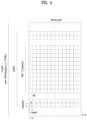
- FIG. 4 illustrates the slot structure of a NR frame to which the present disclosure is applicable.
- one slot includes a plurality of symbols in the time domain.
- one slot may include 14 symbols in a normal CP and 12 symbols in an extended CP.
- one slot may include 7 symbols in the normal CP and 6 symbols in the extended CP.
- a carrier may include a plurality of subcarriers in the frequency domain.
- a resource block (RB) is defined as a plurality of consecutive subcarriers (e.g., 12 subcarriers) in the frequency domain.
- a bandwidth part (BWP) may be defined as a plurality of consecutive (P)RBs in the frequency domain, and the BWP may correspond to one numerology (e.g., SCS, CP length, etc.).
- the carrier may include up to N (e.g., 5) BWPs. Data communication may be conducted in an activated BWP.
- each element may be referred to as a resource element (RE) and may be mapped to one complex symbol.
- RE resource element
- the wireless interface between UEs or the wireless interface between a UE and a network may be composed of an L1 layer, an L2 layer, and an L3 layer.
- the L1 layer may represent a physical layer.
- the L2 layer may represent, for example, at least one of a MAC layer, an RLC layer, a PDCP layer, and an SDAP layer.
- the L3 layer may represent, for example, an RRC layer.
- up to 400 MHz may be supported per component carrier (CC).
- CC component carrier
- a UE operating on a wideband CC always operates with the RF for the entire CCs turned on, the battery consumption of the UE may be increased.
- different numerologies e.g., sub-carrier spacings
- the capability for the maximum bandwidth may differ among the UEs.
- the BS may instruct the UE to operate only in a partial bandwidth, not the entire bandwidth of the wideband CC.
- the partial bandwidth is defined as a bandwidth part (BWP) for simplicity.
- the BWP may be composed of resource blocks (RBs) contiguous on the frequency axis, and may correspond to one numerology (e.g., sub-carrier spacing, CP length, slot/mini-slot duration).
- numerology e.g., sub-carrier spacing, CP length, slot/mini-slot duration
- the BS may configure multiple BWPs in one CC configured for the UE. For example, a BWP occupying a relatively small frequency region may be configured in a PDCCH monitoring slot, and a PDSCH indicated by the PDCCH in a larger BWP may be scheduled. Alternatively, when UEs are concentrated in a specific BWP, some of the UEs may be configured in another BWP for load balancing. Alternatively, a spectrum in the middle of the entire bandwidth may be punctured and two BWPs on both sides may be configured in the same slot in consideration of frequency-domain inter-cell interference cancellation between neighbor cells.
- the BS may configure at least one DL/UL BWP for the UE associated with the wideband CC and activate at least one DL/UL BWP among the configured DL/UL BWP(s) at a specific time (through L1 signaling, MAC CE or RRC signalling, etc.).
- the BS may instruct the UE to switch to another configured DL/UL BWP (through L1 signaling, MAC CE or RRC signalling, etc.).
- the UE may switch to a predetermined DL/UL BWP.
- the activated DL/UL BWP is defined as an active DL/UL BWP.
- the UE may fail to receive DL/UL BWP configuration during an initial access procedure or before an RRC connection is set up.
- a DL/UL BWP assumed by the UE in this situation is defined as an initial active DL/UL BWP.
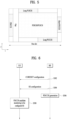
- FIG. 5 illustrates an example of mapping physical channels in a slot.
- a slot may include a DL control channel, DL or UL data, a UL control channel, etc., all of which are included.
- the first N symbols in a slot may be used to transmit a DL control channel (hereinafter, referred to as a DL control region), and the last M symbols in the slot may be used to transmit a UL control channel (hereinafter, referred to as a UL control region).
- N and M are each integers greater than or equal to 0.
- a resource region hereinafter, referred to as a data region
- a time gap for DL-to-UL or UL-to-DL switching may exist between the control region and the data region.
- a PDCCH may be transmitted in the DL control region, and a PDSCH may be transmitted in the DL data region.
- a frame is characterized by a self-contained structure in which all of a DL control channel, DL or UL data, and a UL channel may be included in one slot.
- the first N symbols of a slot may be used to carry a DL channel (e.g., PDCCH) (hereinafter, referred to as a DL control region), and the last M symbols of the slot may be used to carry a UL channel (e.g., PUCCH) (hereinafter, referred to as a UL control region).
- a DL channel e.g., PDCCH
- UL control region e.g., PUCCH
- a resource area (hereinafter, referred to as a data region) between the DL control region and the UL control region may be used to transmit DL data (e.g., PDSCH) or UL data (e.g., PUSCH).
- DL data e.g., PDSCH
- UL data e.g., PUSCH
- a guard period (GP) provides a time gap for switching from a transmission mode to a reception mode or from the reception mode to the transmission mode.
- the PDCCH delivers DCI.
- the PDCCH i.e., DCI
- the PDCCH may carry information about a transport format and resource allocation of a DL shared channel (DL-SCH), resource allocation information of an uplink shared channel (UL-SCH), paging information on a paging channel (PCH), system information on the DL-SCH, information on resource allocation of a higher-layer control message such as an RAR transmitted on a PDSCH, a transmit power control command, information about activation/release of configured scheduling, and so on.
- the DCI includes a cyclic redundancy check (CRC).
- the CRC is masked with various identifiers (IDs) (e.g.
- RNTI radio network temporary identifier
- the CRC is masked by a UE ID (e.g., cell-RNTI (C-RNTI)).
- C-RNTI cell-RNTI
- P-RNTI paging-RNTI
- SIB system information block
- SI-RNTI system information RNTI
- RA-RNTI random access-RNTI
- FIG. 6 illustrates an exemplary PDCCH transmission/reception process.
- a BS may transmit a control resource set (CORESET) configuration to a UE (S502).
- CORESET is defined as a resource element group (REG) set having a given numerology (e.g., a subcarrier spacing (SCS), a cyclic prefix (CP) length, and so on).
- An REG is defined as one OFDM symbol by one (physical) resource block (P)RB.
- a plurality of CORESETs for one UE may overlap with each other in the time/frequency domain.
- a CORESET may be configured by system information (e.g., a master information block (MIB)) or higher-layer signaling (e.g., radio resource control (RRC) signaling).
- MIB master information block
- RRC radio resource control
- configuration information about a specific common CORESET may be transmitted in the MIB.
- a PDSCH carrying system information block 1 (SIB1) may be scheduled by a specific PDCCH, and CORESET #0 may be used to transmit the specific PDCCH.
- System information (SIB1) broadcast in a cell includes cell-specific PDSCH configuration information, PDSCH-ConfigCommon.
- PDSCH-ConfigCommon includes a list (or look-up table) of parameters related to a time-domain resource allocation, pdsch-TimeDomainAllocationList.
- Each pdsch-TimeDomainAllocationList may include up to 16 entries (or rows) each being joint-encoded ⁇ K0, PDSCH mapping type, PDSCH start symbol and length (SLIV) ⁇ .
- pdsch-TimeDomainAllocationList may be provided through a UE-specific PDSCH configuration, PDSCH-Config.
- pdsch-TimeDomainAllocationList configured UE-specifically has the same structure as pdsch-TimeDomainAllocationList provided UE-commonly. For K0 and an SLIV of pdsch-TimeDomainAllocationList, the following description is referred to.
- configuration information about CORESET #N may be transmitted by RRC signaling (e.g., cell-common RRC signaling, UE-specific RRC signaling, or the like).
- RRC signaling e.g., cell-common RRC signaling, UE-specific RRC signaling, or the like.
- the UE-specific RRC signaling carrying CORESET configuration information may include, but not limited to, various types of signaling such as an RRC setup message, an RRC reconfiguration message, and/or BWP configuration information.
- a CORESET configuration may include the following information/fields.
- the BS may transmit a PDCCH search space (SS) configuration to the UE (S504).
- the PDCCH SS configuration may be transmitted by higher-layer signaling (e.g., RRC signaling).
- RRC signaling may include, but not limited to, various types of signaling such as an RRC setup message, an RRC reconfiguration message, and/or BWP configuration information.
- a CORESET configuration and a PDCCH SS configuration are shown as separately signaled in FIG. 5 , for convenience of description, the present disclosure is not limited thereto.
- the CORESET configuration and the PDCCH SS configuration may be transmitted in one message (e.g., by one RRC signaling) or separately in different messages.
- the PDCCH SS configuration may include information about the configuration of a PDCCH SS set.
- the PDCCH SS set may be defined as a set of PDCCH candidates monitored (e.g., blind-detected) by the UE.
- One or more SS sets may be configured for the UE.
- Each SS set may be a UE-specific search space (USS) set or a common search space (CSS) set.
- USS UE-specific search space
- SCS common search space
- PDCCH SS set may be referred to as "SS" or "PDCCH SS".
- a PDCCH SS set includes PDCCH candidates.
- a PDCCH candidate is CCE(s) that the UE monitors to receive/detect a PDCCH. The monitoring includes blind decoding (BD) of PDCCH candidates.
- One PDCCH (candidate) includes 1, 2, 4, 8, or 16 CCEs according to an aggregation level (AL).
- One CCE includes 6 REGs.
- Each CORESET configuration is associated with one or more SSs, and each SS is associated with one CORESET configuration.
- One SS is defined based on one SS configuration, and the SS configuration may include the following information/fields.
- the BS may generate a PDCCH and transmit the PDCCH to the UE (S506), and the UE may monitor PDCCH candidates in one or more SSs to receive/detect the PDCCH (S508).
- An occasion e.g., time/frequency resources
- PDCCH (monitoring) occasion is defined as a PDCCH (monitoring) occasion.
- One or more PDCCH (monitoring) occasions may be configured in a slot.
- Table 5 shows the characteristics of each SS.
- Type Search Space RNTI Use Case Type0-PDCCH Common SI-RNTI on a primary cell SIB Decoding Type0A-PDCCH Common SI-RNTI on a primary cell SIB Decoding Type1-PDCCH Common RA-RNTI or TC-RNTI on a primary cell Msg2, Msg4 decoding in RACH Type2-PDCCH Common P-RNTI on a primary cell Paging Decoding Type3-PDCCH Common INT-RNTI, SFI-RNTI, TPC-PUSCH-RNTI, TPC-PUCCH-RNTI, TPC-SRS-RNTI, C-RNTI, MCS-C-RNTI, or CS-RNTI(s) UE Specific UE Specific C-RNTI, or MCS-C-RNTI, or CS-RNTI(s) User specific PDSCH decoding
- Table 6 shows DCI formats transmitted on the PDCCH.
- DCI format 0_0 may be used to schedule a TB-based (or TB-level) PUSCH
- DCI format 0_1 may be used to schedule a TB-based (or TB-level) PUSCH or a code block group (CBG)-based (or CBG-level) PUSCH
- DCI format 1_0 may be used to schedule a TB-based (or TB-level) PDSCH
- DCI format 1_1 may be used to schedule a TB-based (or TB-level) PDSCH or a CBG-based (or CBG-level) PDSCH (DL grant DCI).
- DCI format 0_0/0_1 may be referred to as UL grant DCI or UL scheduling information
- DCI format 1_0/1_1 may be referred to as DL grant DCI or DL scheduling information
- DCI format 2_0 is used to deliver dynamic slot format information (e.g., a dynamic slot format indicator (SFI)) to a UE
- DCI format 2_1 is used to deliver DL pre-emption information to a UE.
- DCI format 2_0 and/or DCI format 2_1 may be delivered to a corresponding group of UEs on a group common PDCCH which is a PDCCH directed to a group of UEs.
- DCI format 0_0 and DCI format 1_0 may be referred to as fallback DCI formats, whereas DCI format 0_1 and DCI format 1_1 may be referred to as non-fallback DCI formats.
- a DCI size/field configuration is maintained to be the same irrespective of a UE configuration.
- the DCI size/field configuration varies depending on a UE configuration in the non-fallback DCI formats.
- a CCE-to-REG mapping type is configured as one of an interleaved CCE-to-REG type and a non-interleaved CCE-to-REG type.
- TDD-UL-DL-ConfigCommon may be configuration information for determining/configuring a cell-specific UL/DL TDD configuration.
- TDD-UL-DL-ConfigCommon may include parameters defined in Table 7. [Table 7]
- TDD-UL-DL-ConfigCommon field descriptions referenceSubcarrierSpacing Reference SCS used to determine the time domain boundaries in the UL-DL pattern which must be common across all subcarrier specific carriers, i.e., independent of the actual subcarrier spacing using for data transmission. Only the values 15, 30 or 60 kHz (FR1), and 60 or 120 kHz (FR2) are applicable.
- the network configures a not larger than any SCS of configured BWPs for the serving cell.
- the network or SL-PreconfigGeneral configures a not larger than the SCS of (pre-)configured SL BWP. See TS 38.213 [13], clause 11.1.
- TDD-UL-DL-Pattern field descriptions dl-UL-TransmissionPeriodicity Periodicity of the DL-UL pattern, see TS 38.213 [13], clause 11.1. If the dl-UL-TransmissionPeriodicity-v1530 is signalled, UE shall ignore the dl-UL-TransmissionPeriodicity (without suffix).
- nrofDownlinkSlots Number of consecutive full DL slots at the beginning of each DL-UL pattern, see TS 38.213 [13], clause 11.1.
- the maximum value for this field is 80.
- nrofDownlinkSymbols Number of consecutive DL symbols in the beginning of the slot following the last full DL slot (as derived from nrofDownlinkSlots ) .
- the value 0 indicates that there is no partial-downlink slot.
- nrofUplinkSlots Number of consecutive full UL slots at the end of each DL-UL pattern, see TS 38.213 [13], clause 11.1.
- the maximum value for this field is 80.
- nrofUplinkSymbols Number of consecutive UL symbols in the end of the slot preceding the first full UL slot (as derived from nrofUplinkSlots ) .
- the value 0 indicates that there is no partial-uplink slot. (see TS 38.213 [13], clause 11.1).
- BWP-DownlinkCommon is configuration information used to configure common parameters of a DL BWP. That is, BWP-DownlinkCommon may include "cell-specific" parameters. Common parameters of an initial BWP of the PCell may also be provided through system information. For all other serving cells, a network may provide the common parameters through dedicated signaling. Specifically, BWP-DownlinkCommon may include parameters defined in Table 8. [Table 8] BWP-DownlinkCommon field descriptions pdcch-ConfigCommon Cell specific parameters for the PDCCH of this BWP. This field is absent for a dormant BWP. pdsch-ConfigCommon Cell specific parameters for the PDSCH of this BWP.
- PDCCH-ConfigCommon may be used to configure cell-specific PDCCH parameters provided through dedicated signaling as well as through an SIB.
- PDCCH-ConfigCommon may include configuration parameters for a cell-specific PDCCH.
- PDCCH-ConfigCommon field descriptions commonControlResourceSet An additional common control resource set which may be configured and used for any common or UE-specific search space. If the network configures this field, it uses a ControlResourceSetId other than 0 for this ControlResourceSet. The network configures the commonControlResourceSet in SIB1 so that it is contained in the bandwidth of CORESET#0.
- commonSearchSpaceList, commonSearchSpaceListExt A list of additional common search spaces.
- the network uses the SearchSpaceIds other than 0. If the field is included, it replaces any previous list, i.e. all the entries of the list are replaced and each of the SearchSpace entries is considered to be newly created and the conditions and Need codes for setup of the entry apply. If the network includes commonSearchSpaceListExt, it includes the same number of entries, and listed in the same order, as in commonSearchSpaceList controlResourceSetZero Parameters of the common CORESET#0 which can be used in any common or UE-specific search spaces. The values are interpreted like the corresponding bits in MIB pdcch-ConfigSIB1.
- controlResourceSetZero can be used in search spaces configured in other DL BWP(s) than the initial DL BWP if the conditions defined in TS 38.213 [13], clause 10 are satisfied.
- f irstPDCCH-MonitoringOccasionOfPO Indicates the first PDCCH monitoring occasion of each PO of the PF on this BWP, see TS 38.304 [20].
- pagingSearchSpace ID of the Search space for paging see TS 38.213 [13], clause 10.1). If the field is absent, the UE does not receive paging in this BWP (see TS 38.213 [13], clause 10).
- ra-SearchSpace ID of the Search space for random access procedure see TS 38.213 [13], clause 10.1. If the field is absent, the UE does not receive RAR in this BWP. This field is mandatory present in the DL BWP(s) if the conditions described in TS 38.321 [3], subclause 5.15 are met. searchSpaceOtherSystemInformation ID of the Search space for other system information, i.e., SIB2 and beyond (see TS 38.213 [13], clause 10.1) If the field is absent, the UE does not receive other system information in this BWP. searchSpaceSIB1 ID of the search space for SIB1 message.
- searchSpaceZero Parameters of the common SearchSpace#0 are interpreted like the corresponding bits in MIB pdcch-ConfigSIB1. Even though this field is only configured in the initial BWP (BWP#0), searchSpaceZero can be used in search spaces configured in other DL BWP(s) than the initial DL BWP if the conditions described in TS 38.213 [13], clause 10, are satisfied.
- PDSCH-ConfigCommon defined in Table 10 is configuration information used to configure a cell-specific PDSCH.
- ServingCellConfigCommon may be used to configure cell-specific parameters of a serving cell of a UE.
- ServingCellConfigCommon may include parameters that the UE typically obtains from a synchronization signal block (SSB), an MIB or an SIB upon accessing a cell in an IDLE state.
- SSB synchronization signal block
- ServingCellConfigCommonSIB defined in Table 12 may be used to configure cell-specific parameters of a serving cell of a UE in SIB1.
- ServingCellConfigCommonSIB field descriptions channelAccessMode If present, this field indicates which channel access procedures to apply for operation with shared spectrum channel access as defined in TS 37.213 [48]. If the field is configured as "semiStatic", the UE shall apply the channel access procedures for semi-static channel occupancy as described in subclause 4.3 in TS 37.213. If the field is configured as "dynamic”t, the UE shall apply the channel access procedures in TS 37.213, with the exception of subclause 4.3 of TS 37.213.
- discoveryBurstWindowLength Indicates the window length of the discovery burst in ms (see TS 37.213 [48]).
- groupPresence This field is present when maximum number of SS/PBCH blocks per half frame equals to 64 as defined in TS 38.213 [13], clause 4.1.
- the first/leftmost bit corresponds to the SS/PBCH index 0-7, the second bit corresponds to SS/PBCH block 8-15, and so on.
- Value 0 in the bitmap indicates that the SSBs according to inOneGroup are absent.
- Value 1 indicates that the SS/PBCH blocks are transmitted in accordance with inOneGroup.
- the UE applies the value defined for the duplex mode and frequency range of this serving cell. See TS 38.133 [14], table 7.1.2-2. ssb-PositionsinBurst Time domain positions of the transmitted SS-blocks in an SS-burst as defined in TS 38.213 [13], clause 4.1.
- BWP-UplinkCommon defined in Table 13 may be used to configure common parameters of a UL BWP and configures parameters for a cell-specific signal.
- BWP-UplinkCommon field descriptions msgA-ConfigCommon Configuration of the cell specific PRACH and PUSCH resource parameters for transmission of MsgA in 2-step random access type procedure.
- the NW can configure msgA-ConfigCommon only for UL BWPs if the linked DL BWPs (same bwp-Id as UL-BWP) are the initial DL BWPs or DL BWPs containing the SSB associated to the initial BL BWP pucch-ConfigCommon Cell specific parameters for the PUCCH of this BWP. pusch-ConfigCommon Cell specific parameters for the PUSCH of this BWP. rach-ConfigCommon Configuration of cell specific random access parameters which the UE uses for contention based and contention free random access as well as for contention based beam failure recovery in this BWP.
- the NW configures SSB-based RA (and hence RACH-ConfigCommon ) only for UL BWPs if the linked DL BWPs (same bwp-Id as UL-BWP) are the initial DL BWPs or DL BWPs containing the SSB associated to the initial DL BWP.
- the network configures rach-ConfigCommon, whenever it configures contention free random access (for reconfiguration with sync or for beam failure recovery).
- rach-ConfigCommonIAB Configuration of cell specific random access parameters for the IAB-MT.
- the IAB specific IAB RACH configuration is used by IAB-MT, if configured.
- the UE uses uplink frequency domain resource allocation Type 2 for cell-specific PUSCH, e.g., PUSCH scheduled by RAR UL grant (see 38.213 clause 8.3 and 38.214 clause 6.1.2.2) and uses interlaced PUCCH Format 0 and 1 for cell-specific PUCCH (see TS 38.213 [13], clause 9.2.1).
- uplink frequency domain resource allocation Type 2 for cell-specific PUSCH, e.g., PUSCH scheduled by RAR UL grant (see 38.213 clause 8.3 and 38.214 clause 6.1.2.2) and uses interlaced PUCCH Format 0 and 1 for cell-specific PUCCH (see TS 38.213 [13], clause 9.2.1).
- initialDownlinkBWP defined in Table 14 may be used to configure an initial DL BWP.
- DownlinkConfigCommonSIB field descriptions bcch-Config The modification period related configuration.
- initialDownlinkBWP The initial downlink BWP configuration for a PCell.
- the network configures the locationAndBandwidth so that the initial downlink BWP contains the entire CORESET#0 of this serving cell in the frequency domain.
- the UE applies the locationAndBandwidth upon reception of this field (e.g.
- nrofPDCCH-MonitoringOccasionPerSSB-InPO The number of PDCCH monitoring occasions corresponding to an SSB within a Paging Occasion, see TS 38.304 [20], clause 7.1.
- pcch-Config The paging related configuration.
- PUCCH-ConfigCommon defined in Table 15 may be used to configure cell-specific PUCCH parameters.
- pucch-ResourceCommon An entry into a 16-row table where each row configures a set of cell-specific PUCCH resources/parameters. The UE uses those PUCCH resources until it is provided with a dedicated PUCCH-Config (e.g. during initial access) on the initial uplink BWP. Once the network provides a dedicated PUCCH-Config for that bandwidth part the UE applies that one instead of the one provided in this field (see TS 38.213 [13], clause 9.2).
- PUSCH-ConfigCommon defined in Table 16 may be used to configure cell-specific PUSCH parameters.
- the NW may configure group hopping by this cell-specific parameter, see TS 38.211 [16], clause 6.4.1.1.1.2.
- Actual value field value * 2 [dB] (see TS 38.213 [13], clause 7.1) p0-NominalWithGrant P0 value for PUSCH with grant (except msg3). Value in dBm.
- step size 2 Only even values (step size 2) allowed (see TS 38.213 [13], clause 7.1)
- This field is cell specific pusch-TimeDomainAllocationList List of time domain allocations for timing of UL assignment to UL data (see TS 38.214 [19], table 6.1.2.1.1-1).
- RACH-ConfigCommon defined in Table 17 may be used to specify or configure cell-specific random access parameters.
- RACH-ConfigCommon field descriptions messagePowerOffsetGroupB Threshold for preamble selection. Value is in dB. Value minusinfinity corresponds to -infinity. Value dB0 corresponds to 0 dB, dB5 corresponds to 5 dB and so on. (see TS 38.321 [3], clause 5.1.2) msg1-SubcarrierSpacing Subcarrier spacing of PRACH (see TS 38.211 [16], clause 5.3.2). Only the values 15 or 30 kHz (FR1), and 60 or 120 kHz (FR2) are applicable.
- the UE applies the SCS as derived from the prech-ConfigurationIndex in RACH-ConfigGeneric (see tables Table 6.3.3.1-1, Table 6.3.3.1-2, Table 6.3.3.2-2 and Table 6.3.3.2-3, TS 38.211 [16]).
- the value also applies to contention free random access ( RACH-ConfigDedicated ), to SI-request and to contention-based beam failure recovery (CB-BFR). But it does not apply for contention free beam failure recovery (CF-BFR) (see BeamFailureRecoveryConfig ).
- msg3-transformPrecoder Enables the transform precoder for Msg3 transmission according to clause 6.1.3 of TS 38.214 [19].
- ra-ContentionResolutionTimer The initial value for the contention resolution timer (see TS 38.321 [3], clause 5.1.5). Value sf8 corresponds to 8 subframes, value sf16 corresponds to 16 subframes, and so on. ra-Msg3SizeGroupA Transport Blocks size threshold in bits below which the UE shall use a contention-based RA preamble of group A.
- ra-Prioritization Parameters which apply for prioritized random access procedure on any UL BWP of SpCell for specific Access Identities (see TS 38.321 [3], clause 5.1.1a).
- ra-PrioritizationForAI Indicates whether the field ra-Prioritization-r16 applies for Access Identities. The first/leftmost bit corresponds to Access Identity 1, the next bit corresponds to Access Identity 2. Value 1 indicates that the field ra-Prioritization-r16 applies otherwise the field does not apply (see TS 23.501 [32]).
- rach-ConfigGeneric RACH parameters for both regular random access and beam failure recovery.
- restrictedSetConfig Configuration of an unrestricted set or one of two types of restricted sets see TS 38.211 [16] clause 6.3.3.1.
- rsrp-ThresholdSSB UE may select the SS block and corresponding PRACH resource for path-loss estimation and (re)transmission based on SS blocks that satisfy the threshold (see TS 38.213 [13]).
- RRC configuration information such as TDD-UL-DL-ConfigCommon, BWP-DownlinkCommon, PDCCH-ConfigCommon, PDSCH-ConfigCommon, ServingCellConfigCommonSIB, BWP-UplinkCommon, initialDownlinkBWP, PUCCH-ConfigCommon, PUSCH-ConfigCommon, and RACH-ConfigCommon may provide configuration information about transmission parameters for a cell-specific signal or channel and/or transmission resources.
- IAB Integrated Access/Backhaul
- Such integrated access and backhaul links may be formed in a network, where an IAB node or relay node (rTRP) can multiplex access and backhaul links in time, frequency, or space (e.g., beam-based operations).
- rTRP relay node
- the operations of different links may be at the same or different frequencies (also referred to as 'in-band' and 'out-band' relays). Efficient support of an out-band relay is important in some NR deployment scenarios, but it is very important to understand in-band operational requirements, which mean close interaction with an access link operating at the same frequency, to accept duplex constraints and avoid/mitigate interference.
- operating an NR system in the mmWave spectrum may present several unique challenges, including experiencing severe short-term blocking that may not be easily mitigated by current RRC-based handover mechanisms due to the larger time scale required to complete a procedure in comparison to short-term blocking.
- a fast RAN-based mechanism (which does not necessarily require intervention of a core network) for inter-rTRP switching.
- the need to mitigate short-term blocking of an NR operation in mmWave spectrum with the need for easier deployment of a self-backhauled NR cell may lead to the need for the development of an integrated framework that enables fast switching of access and backhaul links.
- OTA Over-The-Air coordination between rTRPs may be considered as mitigating interference and supporting end-to-end route selection and optimization.
- IAB integrated access and wireless backhaul
- Legacy NR new RAT
- half duplex of an IAB scenario is supported and worthy of being targeted.
- a full duplex IAB device may be studied.
- a Donor gNB In the IAB scenario, if each IAB node or Relay Node (RN) does not have scheduling capability, a Donor gNB (DgNB) must schedule the entire links among DgNB-related RNs and UEs. In other words, the DgNB may collect traffic information from all related RNs, make scheduling decisions for all links, and then inform each RN of schedule information.
- DgNB Donor gNB
- FIG. 7 schematically illustrates an example of a parent link and a child link.
- a link between an IAB node and a parent node is called a parent link
- a link between an IAB node and a child node/UE is called a child link. That is, a link between MT and parent DU is called a parent link, and a link between DU and child MT/UE is called a child link.
- a link between an IAB node and a parent node may be called a backhaul link
- a link between an IAB node and a child node/UE may be called an access link
- An IAB node may receive a slot format configuration for communication with a parent node and a slot format configuration for communication with a child node/access UE.
- a TDM operation in which a DU and an MT operate through different time resources has been performed.
- resource multiplexing such as SDM/FDM, FC, etc. between the DU and the MT is required for efficient resource operation.
- a link between the IAB node (IAB MT) and the parent node is referred to as a parent link
- a link between the IAB node (IAB DU) and the child node (child MT) is referred to as a child link.
- the TDM operation between the parent link and the child link has been discussed, and the SDM/FDM and FD operations are being discussed.
- the DU and the MT existing in the same IAB node cannot operate simultaneously due to intra-node interference, slot/symbol boundary misalignment, power sharing, etc., and can operate in TDM.
- multiplexing of SDM/FDM may be used between the DU and the MT. Such multiplexing is applicable to an example case in which, since DU and MT use different panels, there is little interference between the panels.
- DU and MT existing (or co-located) in the same IAB node can transmit or receive data or information simultaneously, but it is impossible for each of the DU and the MT to perform transmission and reception simultaneously or to perform reception and transmission simultaneously.
- FD may be used between the DU and the MT. This is applicable in cases where there is little interference between the DU and the MT, such as when a frequency domain where the DU operates and a frequency domain where the MT operates are far apart.
- the DU and the MT existing in the same IAB node (or co-located) can freely transmit and receive data simultaneously.
- the DU and the MT can transmit or receive data simultaneously, and it is also possible for each of the DU and the MT to perform transmission and reception simultaneously or to perform reception and transmission simultaneously.
- N MT-CCs and M DU-cells may exist in the IAB node.
- MT-CCs existing in the IAB node may operate through the same or different frequency resources, and one MT-CC may be connected to one or more parent DU-cells.
- DU-cells existing in the IAB node may operate through the same or different frequency resources.
- the MT-CC and the DU-cell may be in either TDM relationship or no-TDM relationship for the following four Tx/Rx direction combinations, and TDM or no-TDM may vary for each Tx/Rx combination.
- all of the four Tx/Rx combinations can operate with TDM.
- the corresponding DU-cell and the corresponding MT-CC should always operate with TDM regardless of Tx/Rx directions of the DU-cell and the MT-CC.
- all of the four Tx/Rx combinations can operate with no-TDM.
- the corresponding DU-cell and MT-CC can always operate simultaneously with no-TDM regardless of the Tx/Rx directions of the DU-cell and MT-CC.
- DU-Tx/MT-Tx and DU-Rx/MT-Rx can operate with no-TDM
- DU-Tx/MT-Rx and DU-Rx/MT-Tx can operate with TDM.
- the above-described operation relates to a method (e.g., SDM/FDM) for allowing simultaneous operation when the Tx/Rx directions of the DU-cell and the MT-CC are the same, and this method can operate simultaneously when the Tx/Rx directions of the DU-cell and the MT-CC are the same.
- TDM/no-TDM information for each Tx/Rx combination can be configured/determined differently or independently for each specific MT-CC/DU-cell pair within the IAB node.
- the IAB MT may be connected to two parent DUs using, for example, a dual-connectivity method or a DAPS-HO method.
- NCR Network-controlled repeater
- IAB Integrated Access and Backhaul
- RF repeaters have seen a wide range of deployments in 2G, 3G and 4G to supplement the coverage provided by regular full-stack cells.
- RAN4 specified RF and EMC requirements for such RF repeaters for NR targeting both FR1 and FR2.
- An RF repeater presents a cost effective means of extending network coverage, it has its limitations. An RF repeater simply does an amplify-and-forward operation without being able to take into account various factors that could improve performance. Such factors may include information on semi-static and/or dynamic downlink/uplink configuration, adaptive transmitter/receiver spatial beamforming, ON-OFF status, etc.
- a network-controlled repeater is an enhancement over conventional RF repeaters with the capability to receive and process side control information from the network.
- Side control information could allow a network-controlled repeater to perform its amplify-and-forward operation in a more efficient manner.
- Potential benefits could include mitigation of unnecessary noise amplification, transmissions and receptions with better spatial directivity, and simplified network integration.
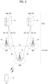
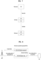
- FIG. 8 is a diagram illustrating an example of topology in which a network-controlled repeater (NCR) performs transmission and reception between the gNB and the UE.
- NCR network-controlled repeater
- the NCR may include a radio unit (RU) and a mobile terminal (MT).
- RU radio unit
- MT mobile terminal
- the gNB may include a central unit (CU) and/or a distributed unit (DU), and the NCR may be connected to the gNB.
- the MT may form a control link with the gNB
- the RU may form a forwarding link for backhaul with the gNB and a forwarding link for access with the UE.
- the RU of the NCR may be composed of only an RF layer.
- the RU may receive a signal transmitted by the gNB through the forwarding link at the RF end and may forward the received signal to the UE.
- the signal received from the UE may be received by the RF end, and the received signal may be forwarded to the gNB.
- the RU may only transmit signals between the gNB and the UE, and may not generate signals/channels by itself and transmit the generated signals/channels to the gNB/UE.
- the RU receives signals/channels from the gNB/UE, but does not detect the received signals/channels.
- the RU may control the directions of the Tx/Rx beams, the DL/UL directions, ON/OFF information, transmission (Tx) power, etc. in the RF end.
- this RU operation cannot be determined by the NCR itself, and can be entirely controlled by the gNB.
- the MT of the above NCR may include an RF layer and L1, L2, and/or L3 layers.
- the MT may include only an RF layer and an L1 layer or may include the L1 and L2 layers.
- the MT may include an RF layer and L1/L2/L3 layers.
- the MT may detect/receive a signal/channel transmitted by the gNB and may generate a signal/channel to be transmitted to the gNB.
- the MT may receive information (e.g., side control information) necessary to control the operation of the RU from the gNB. Meanwhile, the MT may not perform transmission and reception with the UE.
- FIG. 9 is a diagram illustrating the radio frequency (RF) repeater and the NCR.
- the power of a signal that is received regardless of whether the gNB and the UE transmit signals is always amplified and transmitted.
- unnecessary power consumption and interference to the surroundings are unavoidably increased.
- the NCR performs ON/OFF operations, and when there is no signal to be transmitted to the gNB and UE, the operation of the RU is turned off, so that unnecessary signals are not transmitted.
- the existing RF repeater has been operated without recognizing a DL/UL slot boundary.
- the NCR in order for the NCR to adaptively adjust beamforming, ON/OFF, DL/UL directions, transmission power, etc. as described above, the NCR must know transmission/reception (Tx/Rx) boundaries of a downlink (DL).
- Tx/Rx transmission/reception
- DL downlink
- the RU operation can be applied differently for each unit time (e.g., slot/symbol).
- the operation in the NCR will be assumed for convenience of description.
- the content described below can be applied to devices other than the NCR.
- the content described below can be applied for the operation of RIS.
- the NCR mentioned in the present disclosure can be replaced with 'RIS' and expanded/interpreted.
- the RU may serve to forward signals from the gNB to the UE in RIS and to forward signals from the UE to the gNB in RIS
- the MT may serve to receive side control information required for controlling signal transmission of the RU from the gNB.
- the term “network” may hereinafter be interpreted as “gNB” or "CU/DU”.
- the term “gNB” may hereinafter be interpreted as "network", "CU", or "DU”.
- the NCR In order for the NCR to forward the signal received by the RU, it may be considered that the directions of transmission/reception (Tx/Rx) beams, DL/UL directions, ON/OFF states, transmission (Tx) power, etc. are adjusted at the RF end.
- the RU operation cannot be determined by the NCR itself, and may be entirely controlled by the gNB.
- the MT may receive information (i.e., side control information) necessary to control the RU operation from the gNB. This side control information may be transmitted through L1/L2 signaling such as MAC-CE and DCI.
- the above-described side control information may include all or part of the following information.
- the NCR may be composed of two parts: an NCR-mobile termination (NCR-MT), which is an entity that receives side control information from the gNB and performs reporting to the gNB, and an NCR-forwarding (NCR-Fwd) which receives a Tx signal of the gNB and forwards the Tx signal to the UE or receives a Tx of the UE and forwards the Tx signal to the gNB.
- NCR-MT NCR-mobile termination
- NCR-Fwd NCR-forwarding
- the NCR assumes an amplify and forward (AF) relay rather than a decode and forward (DF) relay. Therefore, since a signal that the NCR-Fwd receives from the UE and transmits to the gNB is simply amplified and forwarded without performing decoding, there may be a limitation in transmitting a Tx signal of the NCR-MT together on such a Tx resource.
- AF amplify and forward
- DF decode and forward
- the NCR-Fwd in order to multiplex an Rx signal received from the UE and a Tx signal of the NCR-MT, the NCR-Fwd should be previously aware of in which time/frequency domain or on which resource the Rx signal received from the UE exists, and the Rx signal and the Tx signal should also be perfectly synchronized.
- recognition of the time/frequency resource of the Rx signal and synchronization matching between the Tx signal and the Rx signal may not be possible in the AF relay.
- side control information which is expected to be received by the NCR in relation to UL TDM of the NCR-MT and the NCR-Fwd or is related to UL TDM, or a prior agreement, which is to be defined in relation to the side control information, may be related to an ON/OFF operation of the NCR. Therefore, an ON/OFF rule of the NCR or UL TDM operations of the NCR-MT and the NCR-Fwd according to the side control information will be described in detail later.
- the UL operation of the NCR may be an operation unrelated to a slot format of the NCR.
- a description will be given based on the UL TDM operations of the NCR-MT and the NCR-Fwd. For example, it is assumed that the NCR-Fwd does not perform UL Tx on a time resource on which the NCR-MT performs UL Tx and that the NCR-MT does not perform UL Tx on a time resource on which the NCR-Fwd performs UL Tx. In addition, it is assumed that the ON/OFF operation of the NCR-Fwd is supported by the NCR.
- the NCR may receive information about a time interval in which the NCR-Fwd is set to ON through the above-described side control information and assume that the NCR-Fwd is indicated as OFF other than the time interval in which the NCR-Fwd is set to ON.
- the ON operation of the NCR-Fwd means that a forwarding operation through a forwarding link may be performed
- the OFF operation of the NCR-Fwd means that the forwarding operation through the forwarding link is not possible.
- the NCR-MT may receive an explicit indication of a time interval or a time resource related to the ON/OFF operation of the NCR-Fwd from the gNB (or BS).
- the NCR may receive, through RRC and/or operations and management (OAM), a semi-static indication of time resource information about ON/OFF of the NCR-Fwd through side control information.
- the NCR may receive a dynamic indication of the time resource information through a medium access control-control element (MAC-CE)/downlink control information (DCI).
- MAC-CE medium access control-control element
- DCI downlink control information
- the NCR may receive not only a semi-static indication of the time resource information through RRC and/or OAM but also a dynamic indication of the time resource information through the MAC-CE/DCI.
- Scenario 1 describes in detail a method of determining whether to transmit a signal of the NCR-MT (UL signal) based on the time resource information about ON/OFF of the NCR-Fwd.
- the time resource information about ON/OFF of the NCR-Fwd by the gNB or the BS is explained by categorizing the time resource information into Case 1 to Case 4.
- time resources may be divided into a time resource for which the NCR-Fwd is indicated as ON (Case 1), a time resource for which the NCR-Fwd is indicated as ON but is overridden by a later indication as OFF (Case 2), a time resource for which the NCR-Fwd is indicated as OFF (Case 3), and a time resource for which the NCR-Fwd is indicated as OFF but is overridden by a later indication as ON (Case 4).
- Cases 1 to 4 above may be applied to a method in which UL Tx of the NCR-MT and UL Tx of the NCR-Fwd are configured not to simultaneously occur.
- Cases 1 to 4 above may be applied to a method for resolving overlap between UL Tx of the NCR-MT and UL Tx of the NCR-Fwd when UL Tx collision between the NCR-MT and the NCR-Fwd occurs (i.e., when the NCR-MT and the NCR-Fwd performs UL Tx on the same time resource or on an overlapping time resource) (although UL Tx of the NCR-MT and UL Tx of the NCR-Fwd are configured not to simultaneously occur or are expected not to simultaneously occur).
- the NCR-MT may always determine that UL Tx of the NCR-MT is impossible on a time resource for which the NCR-Fwd is indicated as ON by the gNB. Specifically, in order to guarantee the TDM operations of the NCR-MT and the NCR-Fwd, the NCR-MT may determine that the NCR-MT is incapable of performing UL Tx on a time resource for which the NCR-Fwd is explicitly indicated as ON by the gNB or may assume that a time resource for DL Rx has been configured. This indication method may be related to the operation of the NCR that expects that UL TDM of the NCR-MT and the NCR-Fwd will be perfectly indicated by a scheduler.
- a UL Tx switching operation between the NCR-MT and the NCR-Fwd may be considered at a symbol level and a slot level. If the UL Tx switching operation between the NCR-MT and the NCR-Fwd is possible at the symbol level, UL Tx of the NCR-MT is not performed on a symbol resource for which the NCR-Fwd is set to ON. If the UL Tx switching operation between the NCR-MT and the NCR-Fwd is possible at the slot level, UL Tx of the NCR-MT may not be performed on a slot resource including the symbol resource for which the NCR-Fwd is set to ON.
- the NCR may determine that all UL Tx of the NCR-MT overlapping with a slot corresponding to the indicated time resource is always impossible. Therefore, UL Tx of the NCR-MT may not be performed in the slot corresponding to the indicated time resource. If the time resource for which the NCR-Fwd is indicated as ON by the gNB is at the symbol level, the NCR may determine that all UL Tx of the NCR-MT overlapping with all slots including the symbol corresponding to the indicated time resource is impossible.
- the NCR-MT may assume that the NCR-Fwd is set to OFF during the scheduled time interval.
- the NCR-MT may perform UL Tx regardless of whether a time interval for ON/OFF of the NCR-Fwd is indicated by the BS. That is, even when the NCR-Fwd is set to ON during a time interval, if the time interval is scheduled as a time resource for UL Tx, the NCR-MT may determine that the NCR-Fwd is indicated as OFF (through control information for scheduling UL Tx of the NCR-MT) during the time interval. In this case, UL Tx of the NCR-Fwd is not performed during the time interval, and UL Tx of the NCR-MT may be performed.
- This method is intended to prioritize UL Tx of the NCR-MT over UL Tx of the NCR-Fwd in consideration of the fact that UL Tx of the NCR-MT corresponding to an entity transmitting and receiving side control information is relatively important compared to UL Tx of the NCR-Fwd and that the time interval of UL Tx of the NCR-MT is scheduled by the gNB.
- a UL Tx switching operation between the NCR-MT and the NCR-Fwd may be considered at a symbol level and a slot level. If the UL Tx switching operation between the NCR-MT and the NCR-Fwd is possible at the symbol level, the NCR-MT may perform UL Tx by determining that the NCR-Fwd is indicated as OFF for an overlapping symbol resource for which the NCR-Fwd is set to ON through UL Tx scheduling of the NCR-MT.
- the NCR-MT may perform UL Tx of the NCR-MT by determining that the NCR-Fwd is indicated as OFF for a slot including the overlapping symbol resource for which the NCR-Fwd is set to ON through UL Tx scheduling of the NCR-MT.
- the NCR-MT is incapable of performing UL Tx except for Tx of a specific signal/channel of the NCR-MT on a time resource for which the NCR-Fwd is set to ON. That is, the NCR-MT may perform Tx of the specific signal/channel by determining that the NCR-Fwd is exceptionally set to and/or indicated as OFF (through scheduling information for scheduling the specific signal/channel) for the time resource for which the NCR-Fwd is set to ON.
- Alt. 3 is a method of prioritizing only UL Tx of the specific signal/channel of the NCR-MT over UL Tx of the NCR-Fwd.
- the NCR-MT may perform UL Tx of the NCR-MT by determining that the NCR-Fwd is set to OFF for Tx of all or part of signals/channels below. That is, the NCR-MT may exceptionally perform UL Tx of all or part of the signals/channels below on an overlapping time resource with a time resource for which the NCR-Fwd is set to ON.
- the NCR may perform only Tx of the NCR-Fwd on a time resource for which the NCR-Fwd is indicated as ON by the gNB for all UL of the NCR-MT except for the above specific signals/channels of the NCR-MT and may drop or cancel Tx of the NCR-MT.
- a UL Tx switching operation between the NCR-MT and the NCR-Fwd may be considered at a symbol level and a slot level. If the UL Tx switching operation between the NCR-MT and the NCR-Fwd is possible at the symbol level, the NCR-MT may perform UL Tx of the NCR-MT by determining that the NCR-Fwd is indicated as OFF for an overlapping symbol resource for which the NCR-Fwd is set to ON through UL Tx scheduling of the NCR-MT based on UL of the NCR-MT being the specific signal/channel.
- the NCR-MT may perform UL Tx of the NCR-MT by determining that the NCR-Fwd is indicated as OFF for a slot including the overlapping symbol resource for which the NCR-Fwd is set to ON through UL Tx scheduling of the NCR-MT based on UL of the NCR-MT being the specific signal/channel.
- the NCR may assume that the NCR-Fwd is set to OFF for the time resource on which the NCR-Fwd is set to ON.
- the NCR may determine that the NCR-Fwd is indicated as OFF for the overlapping time resource.
- This method is intended to prioritize UL Tx of the NCR-MT over UL Tx of the NCR-Fwd in consideration of the fact that UL Tx of the NCR-MT corresponding to an entity transmitting and receiving the side control information is relatively important compared to UL Tx of the NCR-Fwd and that the time interval of UL Tx of the NCR-MT is scheduled by the gNB.
- UL Tx of the NCR-MT is prioritized over UL Tx of the NCR-Fwd only for a signal/channel for which actual UL Tx occurs.
- UL Tx of the NCR-Fwd is not prioritized over potential UL Tx of the NCR-MT even for a UL Tx resource for which the NCR-MT is expected to perform Tx even if the NCR-MT does not actually perform Tx.
- the NCR may not perform UL Tx of the NCR-Fwd by determining that the NCR-Fwd is indicated as OFF even if the NCR-Fwd is set to ON.
- RO RACH occasion
- a UL Tx switching operation between the NCR-MT and the NCR-Fwd may be considered at a symbol level and a slot level. If the UL Tx switching operation between the NCR-MT and the NCR-Fwd is possible at the symbol level, the NCR-MT may determine that the NCR-Fwd is indicated as OFF for an overlapping symbol for which the NCR-Fwd is set to ON with a time resource for which UL Tx of the NCR-MT is expected. In this case, the NCR-MT may perform UL Tx on the overlapping time resource.
- the NCR-MT may perform UL Tx by determining that the NCR-Fwd is indicated as OFF for (all) slots including the overlapping symbol for which the NCR-Fwd is set to ON with the time resource for which UL Tx of the NCR-MT is expected.
- Case 2 is related to handling a time resource for which the NCR-MT receives an indication or configuration indicating that the NCR-Fwd has been set to ON from the gNB but for which the NCR-Fwd is later indicated as or set to OFF by the gNB.
- the time resource may mean a time resource for which the NCR-Fwd has been semi-statically indicated as or set to ON through a signal such as a MAC-CE but is later indicated as OFF through a dynamic signal such as DCI (i.e., a resource for which an indication is overridden).
- the indication for the NCR-MT received from the gNB means an explicit indication through signaling such as RRC/MAC-CE/DCI.
- the NCR-MT receives an indication or configuration indicating that the NCR-Fwd is set to ON for a specific time resource through RRC/OAC from the gNB
- the NCR-Fwd is overlappingly indicated as OFF for the time resource for which the NCR-Fwd is indicated as or set to ON by the gNB through a MAC-CE/DCI.
- the operation of the NCR-MT in a situation in which the NCR-Fwd is newly indicated as OFF by the gNB for a time resource for which the NCR-Fwd is indicated as ON will be described.
- the NCR-MT may operate identically for a resource for which the NCR-Fwd is set to OFF, regardless of whether the time resource is overridden. In other words, if the NCR-Fwd is indicated as or set to OFF by the gNB after a first time resource which is a time resource for which the NCR-Fwd is indicated as or set to ON by the gNB, the NCR-MT may consider that the first time resource is a time resource for which the NCR-Fwd is indicated as OFF even if there is an overlapping indication or configuration with the first time resource.
- Alt. 1 of Case 2 may perform the same operation as the operation of the NCR-MT in Alt. 1, Alt. 2, and Alt. 3 of Case 3 described below.
- the operation of the NCR-MT on a time resource for which the NCR-Fwd is set to OFF after being set to ON is the same as the operation of the NCR-MT on a time resource for which the NCR-Fwd is set to OFF. That is, even if the NCR-Fwd is indicated as OFF from ON for a resource, the NCR may expect that the scheduler will notify such an operation (or only an operation for an indication of OFF) according to requirements for the operation.
- the NCR-MT may operate in consideration of whether a time resource is overridden. For example, a UL Tx operation of the NCR-MT on a time resource for which the NCR-Fwd is set to OFF may be different from a UL Tx operation of the NCR-MT on a time resource for which the NCR-Fwd has been set to ON but is later overridden to OFF.
- the NCR-MT may perform different operations on a time resource for which the NCR-Fwd is set to OFF after being set to ON and on a time resource for which NCR-Fwd is set to OFF.
- the NCR-MT may consider operations thereof based on one of Alt. 1, Alt. 2, and Alt. 3 of Case 3 described later for a time resource for which the NCR-Fwd is set to OFF after being set to ON and for a time resource for which the NCR-Fwd is set to OFF.
- the operation of the NCR-MT may differ depending on time line requirements of the NCR.
- a time line requirement of the NCR-MT and a time line requirement of the NCR-Fwd may be considered separately or together.
- the time line requirement of the NCR-MT may be related to a preparation time required for Tx (e.g., Tx time line requirement).
- Tx time line requirement e.g., Tx time line requirement
- an existing time line requirement such as a PUSCH preparation time of the NCR-MT may be applied to a resource for which the NCR-Fwd is set to OFF by the gNB.
- the time line requirement such as the PUSCH preparation time of the NCR-MT may not be applied to a resource for which the NCR-Fwd has been set to ON by the gNB but is later set back to OFF according to an indication by the gNB.
- the time line requirement of the NCR-MT is not satisfied for the resource for which the NCR-Fwd has been set to ON by gNB but is later set to OFF according to the indication by the gNB, the NCR-MT may not perform UL Tx even though the NCR-Fwd is set to OFF.
- a first time line requirement for a time resource for which NCR-Fwd is set to OFF from the beginning and a second time line requirement for a time resource for which the NCR-Fwd has been set to ON but is later set to OFF according to the indication by the gNB may be different from each other.
- the first time line requirement may be set to a shorter time than the second time line requirement.
- a UL Tx operation of the NCR-MT may differ depending on a time line requirement for ON/OFF of the NCR-Fwd. For example, a transition time may be required to switch UL TX of the NCR-Fwd from ON to OFF, or a time required for the NCR-Fwd may be required to deactivate RF.
- the NCR-MT may previously report information about a time line requirement related to such an ON/OFF operation of the NCR-Fwd to the gNB through RRC/MAC-CE/UCI, etc. Therefore, the gNB may expect that UL Tx of the NCR-MT may be performed on a time resource for which the NCR-Fwd is set to OFF.
- the gNB may predict that the NCR-Fwd may not be set to OFF for a reason such as the time line requirement of the NCR-Fwd for a time resource for which the NCR-Fwd is indicated back as OFF after being set to ON or predict that UL Tx of the NCR-MT may not be performed even if the NCR-Fwd is set to OFF.
- Case 3 relates to a UL Tx operation of the NCR-MT on a time resource for which the NCR-Fwd is indicated as OFF by the gNB.
- the NCR-MT may always perform UL Tx on a time resource for which the NCR-Fwd is indicated as or set to OFF by the gNB. That is, in order to guarantee the TDM operations of the NCR-MT and the NCR-Fwd, the NCR-MT may determine that UL Tx of the NCR-MT may always be performed on a time resource for which the NCR-Fwd is explicitly indicated as OFF by the gNB.
- a UL Tx switching operation between the NCR-MT and the NCR-Fwd may be considered at a symbol level and a slot level. If the UL Tx switching operation between the NCR-MT and the NCR-Fwd is possible at the symbol level, the NCR-MT may always perform UL Tx of the NCR-MT on an overlapping symbol resource for which the NCR-Fwd is set to OFF through UL Tx scheduling of the NCR-MT.
- the NCR-MT may always perform UL Tx of the NCR-MT for slots including the overlapping symbol resource for which the NCR-Fwd is set to OFF through UL Tx scheduling of the NCR-MT.
- the NCR-MT may perform UL Tx only on the time resource only if there is an additional or separate indication.
- the NCR-MT may receive an indication of a periodicity and/or an offset of a time interval in which Tx is expected to be possible from the gNB at a symbol level or a slot level through RRC/MAC-CE/DCI. It may be considered that UL Tx of the NCR-MT is performed only on a time resource for which the NCR-Fwd is set to OFF in the time interval in which Tx of the NCR-MT is expected to be possible according to such an indication by the gNB.
- the NCR-MT performs UL Tx only for a specific signal/channel. For example, even if the NCR-Fwd is set to OFF, the NCR-MT may perform UL Tx of the NCR-MT for Tx of all or part of the following signals/channels. In other words, even if there is a time resource for which the NCR-Fwd is set to OFF, the NCR-MT may allow UL Tx only for the specific signals/channels described below.
- the NCR-MT may determine that the NCR-Fwd is set to ON for the time resource.
- cell-specific UL may be the UL defined in Tables 7 to 17. In other words, even when the NCR-Fwd is set to OFF for a time resource, if UL forwarding of a cell-specific signal by the NCR-Fwd is expected to be performed on the time resource, the NCR-MT may determine that the NCR-Fwd is exceptionally set to ON for the time resource.
- the NCR-MT is incapable of performing UL Tx in a time interval in which the NCR-Fwd is indicated as or set to ON by the gNB or on a time resource for which cell-specific UL forwarding is expected to be required (a resource on which a cell-specifically configured UE is expected to perform or be capable of performing UL Tx).
- a time resource for which cell-specific UL forwarding is expected to be required may be predicted based on cell-specifically configured ROs and/or time resource information scheduled for cell-specific (or cell common) UL Tx of the UE (see Tables 7 to 17).
- the NCR-MT may consider or determine that the NCR-Fwd has been indicated as ON by the gNB. If the expected time resources (time resources on which cell-specifically, cell-commonly, or UE-group-commonly configured UL Tx is expected or predicted by gNB to be performed by the UE) are indicated at a symbol level, the NCR may determine or consider that the NCR-Fwd is indicated as ON by the gNB for all slots including symbols which are the expected time resources.
- the NCR or the NCR MT may predict time/frequency resources on which cell-specific signals for the UE are to be transmitted through system information or RRC configuration information received from the gNB or the BS and may consider that the NCR-Fwd is set to ON for expected resources, which are the predicted time/frequency resources, or expected time resources even if the NCR-Fwd is not separately indicated as ON (or even if the NCR-Fwd is indicated as OFF) by the gNB for the expected resources or the expected time resources.
- Case 4 relates to a time resource for which the NCR-Fwd has been indicated as OFF by the gNB but is later overridden to ON according to an indication by the gNB.
- the NCR-MT may operate in correspondence to the operation of the NCR-MT for a resource for which the NCR-Fwd is set to ON, regardless of whether the resource is overridden.
- the NCR-MT may perform an operation corresponding to the operation of the NCR-MT in Alt. 1, Alt. 2, Alt. 3, and Alt. 4 of Case 1 described above. That is, the operation of the NCR-MT for a time resource for which the NCR-Fwd is set to ON after being set to OFF may be the same as the operation for a time resource for which the NCR-Fwd is set to ON.
- the NCR-MT may operate differently depending on whether the NCR-Fwd is overridden to ON/OFF. For example, a Tx operation of the NCR-MT on a time resource for which the NCR-Fwd is set to ON may be different from a Tx operation of the NCR-MT on a time resource for which the NCR-Fwd has been set to OFF but is later overridden to ON.
- the operation of the NCR-MT may differ depending on time line requirements of the NCR. Specifically, a time line requirement of the NCR-MT and a time line requirement of the NCR-Fwd may be considered separately or together.
- the time line requirement of the NCR-MT may be about, i.e., a Tx time line requirement. For example, since UL Tx of the NCR-MT is not expected for a resource for which the NCR-Fwd is set to ON by the gNB, the time line requirement of the NCR-MT is not considered.
- a time line requirement for cancellation of UL Tx of the NCR-MT may be additionally considered.
- a UL Tx operation of the NCR-MT may be performed without performing UL Tx of the NCR-Fwd even though the NCR-Fwd is set to ON.
- the UL Tx operation of the NCR-MT may differ depending on a time line requirement for ON/OFF of the NCR-Fwd.
- a transition time may be required to switch from OFF to ON of the NCR-Fwd, or a time may be required to deactivate RF.
- the NCR-MT may previously report information about a time line requirement (e.g., information about the transition time) for an ON/OFF operation of the NCR-Fwd to the gNB through RRC/MAC-CE/UCI, etc.
- the gNB may predict that UL Tx of the NCR-Fwd will not be performed for a time resource for which switch from OFF of the NCR-Fwd to ON of the NCR-Fwd is indicated based on the reported information.
- the gNB may predict that UL Tx of the NCR-MT, rather than the operation of the NCR-Fwd, will be performed on a time resource for which the NCR-Fwd is indicated as or set to ON from OFF based on the reported information.
- the NCR-MT may not receive an explicit indication of a time interval or a time resource for which the ON/OFF operation of the NCR-Fwd is performed from the gNB.
- the time resource/time interval related to the ON/OFF operation of the NCR-Fwd may be implicitly determined or configured based on a combination of side control information of various types (e.g., beamforming information, TDD configuration, power control information, etc.).
- the NCR may implicitly determine the time resource/time interval related to the ON/OFF operation of the NCR-Fwd based on the operation of the NCR-MT such as whether the NCR-MT performs Tx.
- the time resource/time interval related to the ON/OFF operation of the NCR-Fwd may be determined or configured based on a time interval or time resource on which UL Tx of the NCR-MT is performed (or depending on whether or not the NCR-MT performs Tx or operation).
- the following alternatives may be applied to two cases. First, the following alternatives may be applied in order to ensure that simultaneous UL Tx operations of the NCR-MT and the NCR-Fwd do not occur. Second, the following alternatives may be applied when the simultaneous UL Tx operations of the NCR-MT and the NCR-Fwd are configured not to occur or in order to resolve collision when collision occurs between the UL Tx operations of the NCR-MT and the NCR-Fwd (i.e., when the NCR-MT and the NCR-Fwd attempt to perform UL Tx on the same time resource or on an overlapping time resource).
- the NCR may determine that the NCR-Fwd is indicated as OFF for resources on which UL Tx of the NCR-MT is actually performed and that the NCR-Fwd is indicated as ON for the remaining resources (time resources on which UL Tx of the NCR-MT is not actually performed).
- the NCR may determine that the NCR-Fwd is set to ON for all time resources by default for whether the NCR-Fwd is set to ON/OFF. That is, if the NCR fails to receive a separate indication regarding whether the NCR-Fwd is set to ON/OFF, the NCR may determine that the NCR-Fwd is set to ON for all time resources but determine that the NCR-Fwd is set to OFF (or is indicated as OFF) only for a time interval in which UL Tx of the NCR-MT is performed.
- the NCR may consider setting the NCR-Fwd to OFF only for symbols in which UL Tx of the NCR-MT is performed. Alternatively, the NCR may determine that the NCR-Fwd is set to OFF for time resources including a time interval for symbols in which UL Tx of the NCR-MT is performed and a time interval for switching an ON/OFF operation of the NCR-Fwd.
- the NCR may determine that the NCR-Fwd is set to OFF for the 1st, 2nd, 3rd, 4th, 5th, 6th, and 7th symbols of the slot (while performing UL Tx of the NCR-MT for the 3rd, 4th, 5th, 6th, and 7th symbols of the slot).
- the NCR may determine that the NCR-Fwd is set to OFF for all slots containing symbols in which UL Tx of the NCR-MT is performed.
- the NCR may determine that the NCR-Fwd is set to OFF for time resources including a time interval for all slots containing symbols in which UL Tx of the NCR-MT is performed and a time interval required for switching the ON/OFF operation of the NCR-Fwd.
- the NCR-MT may perform UL Tx in the 3rd, 4th, 5th, 6th, and 7th symbols of the i-th slot but the NCR-Fwd may be set to OFF in the last two symbols of the (i-1)-th slot, the entirety of the i-th slot, and the first symbol of the (i+1)-th slot.
- the NCR may determine that the NCR-Fwd is set to OFF even for time resources on which UL Tx of the NCR-MT will be expected to be performed or UL Tx of the NCR-MT is predicted and that the NCR-Fwd is always set to ON for all of the remaining time resources except for the expected/predicted time resources.
- the NCR may determine that the NCR-Fwd is set to ON for all time resources by default for whether the NCR-Fwd is set to ON/OFF. In addition, the NCR may determine that the NCR-Fwd is indicated as OFF even for time resources for which the NCR-MT is indicated to be capable of performing UL Tx or the NCR-MT is expected to perform UL Tx, regardless of whether the NCR-MT actually performs UL Tx.
- This method is intended to prioritize UL Tx of the NCR-MT over UL Tx of the NCR-Fwd in consideration of the fact that UL Tx of the NCR-MT corresponding to an entity transmitting and receiving the side control information is relatively important compared to UL Tx of the NCR-Fwd and that a time interval of UL Tx of the NCR-MT is scheduled by the gNB.
- UL Tx of the NCR-MT has priority over UL Tx of the NCR-Fwd only for a signal/channel for which UL Tx is actually performed, whereas, in Alt.
- UL Tx of the NCR-MT even for a time resource on which UL Tx of the NCR-MT is predicted or expected to be performed may be prioritized over UL Tx of the NCR-Fwd.
- the NCR may determine or consider that the NCR-Fwd is indicated as OFF for a time resource on which UL Tx of the NCR-MT is expected, such as a time resource configured as an RO, which is an RACH Tx resource of the NCR-MT configured by gNB or a periodicity and an offset configured for a CG PUSCH, and/or a time resource explicitly allowing UL Tx of the NCR-MT.
- a time resource configured as an RO which is an RACH Tx resource of the NCR-MT configured by gNB or a periodicity and an offset configured for a CG PUSCH
- the NCR may determine that the NCR-Fwd is set to OFF for a slot including some symbols that overlap with a time interval in which UL Tx of the NCR-MT may occur among slots of the time resource.
- the NCR may determine that the NCR-Fwd is set to OFF for symbols that overlap with a time interval in which UL Tx of the NCR-MT may occur or a slot that includes the symbols among symbols indicated as the time resource.
- FIG. 10 is a diagram illustrating a method for a device to perform a forwarding operation on a forwarding link and a UL Tx operation on a C-link.
- the device may correspond to an NCR including an NCR-MT that receives control information or transmits a UL signal through a C-link formed with a BS or a gNB, and an NCR-Fwd that relays or amplifies an Rx signal (or, an Rx UL signal) received from a UE and forwards the Rx signal to the BS through a forwarding link.
- the device may perform a forwarding operation on the forwarding link or a Tx operation of the UL signal on the C-link based on TDM. For example, the device may not simultaneously perform the forwarding operation and the Tx operation of the UL signal.
- UL Tx of the NCR-MT is defined as Tx of the UL signal or a Tx operation of the UL signal on the C-link
- ON/OFF of the NCR-Fwd is defined as ON/OFF of the forwarding operation on the forwarding link.
- ON of the forwarding operation includes not only an operation of actually performing forwarding of a received Rx signal, but also a standby case so that forwarding of the Rx signal is capable of being performed.
- the device may configure a first time resource on which the forwarding operation on the forwarding link is performed is configured (S101).
- the first time resource may be configured or determined, as described above, based on side control information about the forwarding link received from the BS through the C-link or separate time resource allocation information about an ON period of the forwarding operation.
- the device may be configured with the first time resource through RRC signaling or may be dynamically configured with the first time resource through DCI or a MAC CE.
- the device may receive scheduling information or resource allocation information (or control information including the scheduling information or the resource allocation information) about a UL signal to be transmitted on the C-link (S103).
- the resource allocation information may include information about a second time resource (or second time resources) for transmitting the UL signal to the BS on the C-link.
- the device may receive the resource allocation information through DCI, etc. transmitted by the BS.
- the device expects that the first time resource on which the forwarding operation is performed and the second time resource for transmitting the UL signal will be subjected to TDM.
- the device may determine whether to perform Tx of the UL signal on the second time resource overlapping the first time resource based on the type of the UL signal scheduled by the resource allocation information or on a payload included in the UL signal (S105).
- the device may drop or cancel Tx of the UL signal by prioritizing the forwarding operation.
- the device may drop or cancel Tx of the UL signal by prioritizing the forwarding operation.
- the specific type of the UL signal may be (or may be preset to) at least one of a UL signal related to performing an RACH procedure (MsgA (a MsgA PRACH or a PUSCH), Msg1, or Msg3), a UL signal scheduled based on a DG (e.g., a DG PUSCH), a UL signal scheduled based on a CG (e.g., a CG PUSCH), or a configured SRS of the NCR-MT for beam management purposes.
- the specific payload may be UCI including an SR or CSI information or may be A/N feedback information for a received PDSCH.
- the device may transmit the UL signal with priority over the forwarding operation even on the second time resource overlapping with the first time resource. That is, the device may determine or assume that the forwarding operation for the first time resource overlapping with the second time resource is indicated as or set to OFF through the control information including the resource allocation information for scheduling the UL signal including the UCI. In this case, the device may perform Tx of the UL signal with priority without performing the forwarding operation on the second time resource. In contrast, if the UL signal to be transmitted on the C-link does not include the UCI, the device may perform the forwarding operation with priority and drop or cancel the Tx of the UL signal.
- the performance of the forwarding operation includes not only the operation of actually performing forwarding of a received Rx signal, but also a standby state for forwarding of the Rx signal. That is, if the UL signal to be transmitted on the C-link does not include the UCI, the device may maintain an ON state of the NCR-Fwd associated with the forwarding link so as to enable forwarding on the forwarding link without performing Tx of the UL signal.
- the device may transmit the UL signal with priority over the forwarding operation even on the second time resource overlapping with the first time resource. That is, the device may set the NCR-Fwd (or wireless unit) related to the forwarding operation to OFF and perform Tx of the UL signal.
- the device may cancel or drop Tx of the UL signal and maintain the NCR-Fwd in an ON state.
- the device performs the forwarding operation with priority over the Tx operation of the UL signal in a time interval configured or indicated by the BS but may exceptionally prioritize the Tx operation of the UL signal over the forwarding operation for Tx of a specific UL signal or a UL signal including a specific payload.
- the forwarding operation in a time interval predictable by the BS is guaranteed, deterioration in service requirements and service quality caused by Tx delay of the UL signal is minimized by exceptionally allowing Tx of the specific UL signal in a time interval overlapping with the above time interval.
- FIG. 11 illustrates a communication system applied to the present disclosure.
- a communication system 1 applied to the present disclosure includes wireless devices, Base Stations (BSs), and a network.
- the wireless devices represent devices performing communication using Radio Access Technology (RAT) (e.g., 5G New RAT (NR)) or Long-Term Evolution (LTE)) and may be referred to as communication/radio/5G devices.
- RAT Radio Access Technology
- the wireless devices may include, without being limited to, a robot 100a, vehicles 100b-1 and 100b-2, an eXtended Reality (XR) device 100c, a hand-held device 100d, a home appliance 100e, an Internet of Things (IoT) device 100f, and an Artificial Intelligence (AI) device/server 400.
- RAT Radio Access Technology
- NR 5G New RAT
- LTE Long-Term Evolution
- the wireless devices may include, without being limited to, a robot 100a, vehicles 100b-1 and 100b-2, an eXtended Reality (XR) device 100c, a hand-held device 100d, a home appliance 100
- the vehicles may include a vehicle having a wireless communication function, an autonomous driving vehicle, and a vehicle capable of performing communication between vehicles.
- the vehicles may include an Unmanned Aerial Vehicle (UAV) (e.g., a drone).
- UAV Unmanned Aerial Vehicle
- the XR device may include an Augmented Reality (AR)/Virtual Reality (VR)/Mixed Reality (MR) device and may be implemented in the form of a Head-Mounted Device (HMD), a Head-Up Display (HUD) mounted in a vehicle, a television, a smartphone, a computer, a wearable device, a home appliance device, a digital signage, a vehicle, a robot, etc.
- the hand-held device may include a smartphone, a smartpad, a wearable device (e.g., a smartwatch or a smartglasses), and a computer (e.g., a notebook).
- the home appliance may include a TV, a refrigerator, and a washing machine.
- the IoT device may include a sensor and a smartmeter.
- the BSs and the network may be implemented as wireless devices and a specific wireless device 200a may operate as a BS/network node with respect to other wireless devices.
- the wireless devices 100a to 100f may be connected to the network 300 via the BSs 200.
- An AI technology may be applied to the wireless devices 100a to 100f and the wireless devices 100a to 100f may be connected to the AI server 400 via the network 300.
- the network 300 may be configured using a 3G network, a 4G (e.g., LTE) network, or a 5G (e.g., NR) network.
- the wireless devices 100a to 100f may communicate with each other through the BSs 200/network 300, the wireless devices 100a to 100f may perform direct communication (e.g., sidelink communication) with each other without passing through the BSs/network.
- the vehicles 100b-1 and 100b-2 may perform direct communication (e.g.
- V2V Vehicle-to-Vehicle
- V2X Vehicle-to-everything
- Wireless communication/connections 150a, 150b, or 150c may be established between the wireless devices 100a to 100f/BS 200, or BS 200/BS 200.
- the wireless communication/connections may be established through various RATs (e.g., 5G NR) such as uplink/downlink communication 150a, sidelink communication 150b (or, D2D communication), or inter BS communication (e.g. relay, Integrated Access Backhaul(IAB)).
- the wireless devices and the BSs/the wireless devices may transmit/receive radio signals to/from each other through the wireless communication/connections 150a and 150b.
- the wireless communication/connections 150a and 150b may transmit/receive signals through various physical channels.
- various configuration information configuring processes various signal processing processes (e.g., channel encoding/decoding, modulation/demodulation, and resource mapping/demapping), and resource allocating processes, for transmitting/receiving radio signals, may be performed based on the various proposals of the present disclosure.
- various signal processing processes e.g., channel encoding/decoding, modulation/demodulation, and resource mapping/demapping
- resource allocating processes for transmitting/receiving radio signals
- FIG. 12 illustrates a wireless device applicable to the present disclosure.
- a first wireless device 100 and a second wireless device 200 may transmit radio signals through a variety of RATs (e.g., LTE and NR).
- ⁇ the first wireless device 100 and the second wireless device 200 ⁇ may correspond to ⁇ the wireless device 100x and the BS 200 ⁇ and/or ⁇ the wireless device 100x and the wireless device 100x ⁇ of FIG. 11 .
- the first wireless device 100 may include one or more processors 102 and one or more memories 104 and additionally further include one or more transceivers 106 and/or one or more antennas 108.
- the processor(s) 102 may control the memory(s) 104 and/or the transceiver(s) 106 and may be configured to implement the descriptions, functions, procedures, proposals, methods, and/or operational flowcharts disclosed in this document.
- the processor(s) 102 may process information within the memory(s) 104 to generate first information/signals and then transmit radio signals including the first information/signals through the transceiver(s) 106.
- the processor(s) 102 may receive radio signals including second information/signals through the transceiver 106 and then store information acquired by processing the second information/signals in the memory(s) 104.
- the memory(s) 104 may be connected to the processor(s) 102 and may store a variety of information related to operations of the processor(s) 102.
- the memory(s) 104 may store software code including commands for performing a part or the entirety of processes controlled by the processor(s) 102 or for performing the descriptions, functions, procedures, proposals, methods, and/or operational flowcharts disclosed in this document.
- the processor(s) 102 and the memory(s) 104 may be a part of a communication modem/circuit/chip designed to implement RAT (e.g., LTE or NR).
- the transceiver(s) 106 may be connected to the processor(s) 102 and transmit and/or receive radio signals through one or more antennas 108.
- Each of the transceiver(s) 106 may include a transmitter and/or a receiver.
- the transceiver(s) 106 may be interchangeably used with Radio Frequency (RF) unit(s).
- the wireless device may represent a communication modem/circuit/chip.
- the first wireless device 100 or the device may include the processor(s) 102 connected to the RF transceiver(s) 106 and include the memory(s) 104.
- the memory(s) 104 may include at least one program capable of performing operations related to the embodiments described with reference to FIGS. 9 and 10 .
- the processor(s) may report capability information related to beam configuration of a backhaul link to the BS through a control link, configures, through the control link, a first time resource on which a forwarding operation on the forwarding link is performed, receives resource allocation information about a second time resource on which transmission of an uplink signal on the control link is performed, and determines whether to perform transmission of the uplink signal with priority over the forwarding operation on the second time resource overlapping with the first time resource based on a type or payload of the uplink signal.
- the second wireless device 200 may include one or more processors 202 and one or more memories 204 and additionally further include one or more transceivers 206 and/or one or more antennas 208.
- the processor(s) 202 may control the memory(s) 204 and/or the transceiver(s) 206 and may be configured to implement the descriptions, functions, procedures, proposals, methods, and/or operational flowcharts disclosed in this document.
- the processor(s) 202 may process information within the memory(s) 204 to generate third information/signals and then transmit radio signals including the third information/signals through the transceiver(s) 206.
- the processor(s) 202 may receive radio signals including fourth information/signals through the transceiver(s) 106 and then store information acquired by processing the fourth information/signals in the memory(s) 204.
- the memory(s) 204 may be connected to the processor(s) 202 and may store a variety of information related to operations of the processor(s) 202.
- the memory(s) 204 may store software code including commands for performing a part or the entirety of processes controlled by the processor(s) 202 or for performing the descriptions, functions, procedures, proposals, methods, and/or operational flowcharts disclosed in this document.
- the processor(s) 202 and the memory(s) 204 may be a part of a communication modem/circuit/chip designed to implement RAT (e.g., LTE or NR).
- the transceiver(s) 206 may be connected to the processor(s) 202 and transmit and/or receive radio signals through one or more antennas 208.
- Each of the transceiver(s) 206 may include a transmitter and/or a receiver.
- the transceiver(s) 206 may be interchangeably used with RF unit(s).
- the wireless device may represent a communication modem/circuit/chip.
- One or more protocol layers may be implemented by, without being limited to, one or more processors 102 and 202.
- the one or more processors 102 and 202 may implement one or more layers (e.g., functional layers such as PHY, MAC, RLC, PDCP, RRC, and SDAP).
- the one or more processors 102 and 202 may generate one or more Protocol Data Units (PDUs) and/or one or more Service Data Unit (SDUs) according to the descriptions, functions, procedures, proposals, methods, and/or operational flowcharts disclosed in this document.
- PDUs Protocol Data Units
- SDUs Service Data Unit
- the one or more processors 102 and 202 may generate messages, control information, data, or information according to the descriptions, functions, procedures, proposals, methods, and/or operational flowcharts disclosed in this document.
- the one or more processors 102 and 202 may generate signals (e.g., baseband signals) including PDUs, SDUs, messages, control information, data, or information according to the descriptions, functions, procedures, proposals, methods, and/or operational flowcharts disclosed in this document and provide the generated signals to the one or more transceivers 106 and 206.
- the one or more processors 102 and 202 may receive the signals (e.g., baseband signals) from the one or more transceivers 106 and 206 and acquire the PDUs, SDUs, messages, control information, data, or information according to the descriptions, functions, procedures, proposals, methods, and/or operational flowcharts disclosed in this document.
- signals e.g., baseband signals
- the one or more processors 102 and 202 may be referred to as controllers, microcontrollers, microprocessors, or microcomputers.
- the one or more processors 102 and 202 may be implemented by hardware, firmware, software, or a combination thereof.
- ASICs Application Specific Integrated Circuits
- DSPs Digital Signal Processors
- DSPDs Digital Signal Processing Devices
- PLDs Programmable Logic Devices
- FPGAs Field Programmable Gate Arrays
- the descriptions, functions, procedures, proposals, methods, and/or operational flowcharts disclosed in this document may be implemented using firmware or software and the firmware or software may be configured to include the modules, procedures, or functions.
- Firmware or software configured to perform the descriptions, functions, procedures, proposals, methods, and/or operational flowcharts disclosed in this document may be included in the one or more processors 102 and 202 or stored in the one or more memories 104 and 204 so as to be driven by the one or more processors 102 and 202.
- the descriptions, functions, procedures, proposals, methods, and/or operational flowcharts disclosed in this document may be implemented using firmware or software in the form of code, commands, and/or a set of commands.
- the one or more memories 104 and 204 may be connected to the one or more processors 102 and 202 and store various types of data, signals, messages, information, programs, code, instructions, and/or commands.
- the one or more memories 104 and 204 may be configured by Read-Only Memories (ROMs), Random Access Memories (RAMs), Electrically Erasable Programmable Read-Only Memories (EPROMs), flash memories, hard drives, registers, cash memories, computer-readable storage media, and/or combinations thereof.
- the one or more memories 104 and 204 may be located at the interior and/or exterior of the one or more processors 102 and 202.
- the one or more memories 104 and 204 may be connected to the one or more processors 102 and 202 through various technologies such as wired or wireless connection.
- the one or more transceivers 106 and 206 may transmit user data, control information, and/or radio signals/channels, mentioned in the methods and/or operational flowcharts of this document, to one or more other devices.
- the one or more transceivers 106 and 206 may receive user data, control information, and/or radio signals/channels, mentioned in the descriptions, functions, procedures, proposals, methods, and/or operational flowcharts disclosed in this document, from one or more other devices.
- the one or more transceivers 106 and 206 may be connected to the one or more processors 102 and 202 and transmit and receive radio signals.
- the one or more processors 102 and 202 may perform control so that the one or more transceivers 106 and 206 may transmit user data, control information, or radio signals to one or more other devices.
- the one or more processors 102 and 202 may perform control so that the one or more transceivers 106 and 206 may receive user data, control information, or radio signals from one or more other devices.
- the one or more transceivers 106 and 206 may be connected to the one or more antennas 108 and 208 and the one or more transceivers 106 and 206 may be configured to transmit and receive user data, control information, and/or radio signals/channels, mentioned in the descriptions, functions, procedures, proposals, methods, and/or operational flowcharts disclosed in this document, through the one or more antennas 108 and 208.
- the one or more antennas may be a plurality of physical antennas or a plurality of logical antennas (e.g., antenna ports).
- the one or more transceivers 106 and 206 may convert received radio signals/channels etc.
- the one or more transceivers 106 and 206 may convert the user data, control information, radio signals/channels, etc. processed using the one or more processors 102 and 202 from the base band signals into the RF band signals.
- the one or more transceivers 106 and 206 may include (analog) oscillators and/or filters.
- FIG. 13 illustrates another example of a wireless device applied to the present disclosure.
- wireless devices 100 and 200 may correspond to the wireless devices 100 and 200 of FIG. 12 and may be configured by various elements, components, units/portions, and/or modules.
- each of the wireless devices 100 and 200 may include a communication unit 110, a control unit 120, a memory unit 130, and additional components 140.
- the communication unit may include a communication circuit 112 and transceiver(s) 114.
- the communication circuit 112 may include the one or more processors 102 and 202 and/or the one or more memories 104 and 204 of FIG. 12 .
- the transceiver(s) 114 may include the one or more transceivers 106 and 206 and/or the one or more antennas 108 and 208 of FIG. 12 .
- the control unit 120 is electrically connected to the communication unit 110, the memory 130, and the additional components 140 and controls overall operation of the wireless devices. For example, the control unit 120 may control an electric/mechanical operation of the wireless device based on programs/code/commands/information stored in the memory unit 130.
- the control unit 120 may transmit the information stored in the memory unit 130 to the exterior (e.g., other communication devices) via the communication unit 110 through a wireless/wired interface or store, in the memory unit 130, information received through the wireless/wired interface from the exterior (e.g., other communication devices) via the communication unit 110.
- the additional components 140 may be variously configured according to types of wireless devices.
- the additional components 140 may include at least one of a power unit/battery, input/output (I/O) unit, a driving unit, and a computing unit.
- the wireless device may be implemented in the form of, without being limited to, the robot (100a of FIG. 11 ), the vehicles (100b-1 and 100b-2 of FIG. 11 ), the XR device (100c of FIG. 11 ), the hand-held device (100d of FIG. 11 ), the home appliance (100e of FIG. 11 ), the IoT device (100f of FIG.
- the wireless device may be used in a mobile or fixed place according to a use-example/service.
- the entirety of the various elements, components, units/portions, and/or modules in the wireless devices 100 and 200 may be connected to each other through a wired interface or at least a part thereof may be wirelessly connected through the communication unit 110.
- the control unit 120 and the communication unit 110 may be connected by wire and the control unit 120 and first units (e.g., 130 and 140) may be wirelessly connected through the communication unit 110.
- Each element, component, unit/portion, and/or module within the wireless devices 100 and 200 may further include one or more elements.
- the control unit 120 may be configured by a set of one or more processors.
- control unit 120 may be configured by a set of a communication control processor, an application processor, an Electronic Control Unit (ECU), a graphical processing unit, and a memory control processor.
- memory 130 may be configured by a Random Access Memory (RAM), a Dynamic RAM (DRAM), a Read Only Memory (ROM)), a flash memory, a volatile memory, a non-volatile memory, and/or a combination thereof.
- RAM Random Access Memory
- DRAM Dynamic RAM
- ROM Read Only Memory
- flash memory a volatile memory
- non-volatile memory and/or a combination thereof.
- wireless communication technologies implemented in the wireless devices (XXX, YYY) of the present specification may include LTE, NR, and 6G, as well as Narrowband Internet of Things for low power communication.
- the NB-IoT technology may be an example of a Low Power Wide Area Network (LPWAN) technology, and may be implemented in standards such as LTE Cat NB1 and/or LTE Cat NB2, and is not limited to the above-described names.
- LPWAN Low Power Wide Area Network
- the wireless communication technology implemented in the wireless devices (XXX, YYY) of the present specification may perform communication based on LTE-M technology.
- the LTE-M technology may be an example of LPWAN technology, and may be referred to by various names such as eMTC (enhanced machine type communication).
- LTE-M technology may be implemented in at least one of a variety of standards, such as 1) LTE CAT 0, 2) LTE Cat M1, 3) LTE Cat M2, 4) LTE non-BL (non-Bandwidth Limited), 5) LTE-MTC, 6) LTE Machine Type Communication, and/or 7) LTE M, and is not limited to the above-described names.
- the wireless communication technology implemented in the wireless devices (XXX, YYY) of the present specification is at least one of ZigBee, Bluetooth, and Low Power Wide Area Network (LPWAN) considering low power communication, and is not limited to the above-described names.
- ZigBee technology can generate personal area networks (PANs) related to small/low-power digital communication based on various standards such as IEEE 802.15.4, and may be called various names.
- embodiments of the present disclosure have been mainly described based on a signal transmission/reception relationship between a terminal and a base station. Such a transmission/reception relationship is extended in the same/similar manner to signal transmission/reception between a terminal and a relay or a base station and a relay.
- a specific operation described as being performed by a base station in this document may be performed by its upper node in some cases. That is, it is obvious that various operations performed for communication with a terminal in a network comprising a plurality of network nodes including a base station may be performed by the base station or network nodes other than the base station.
- the base station may be replaced by terms such as a fixed station, a Node B, an eNode B (eNB), an access point, and the like.
- the terminal may be replaced with terms such as User Equipment (UE), Mobile Station (MS), Mobile Subscriber Station (MSS).
- UE User Equipment
- MS Mobile Station
- MSS Mobile Subscriber Station
- the embodiments of the present disclosure may be achieved by one or more application specific integrated circuits (ASICs), digital signal processors (DSPs), digital signal processing devices (DSPDs), programmable logic devices (PLDs), field programmable gate arrays (FPGAs), processors, controllers, microcontrollers, microprocessors, etc.
- ASICs application specific integrated circuits
- DSPs digital signal processors
- DSPDs digital signal processing devices
- PLDs programmable logic devices
- FPGAs field programmable gate arrays
- processors controllers, microcontrollers, microprocessors, etc.
- a method according to embodiments of the present disclosure may be implemented in the form of a module, a procedure, a function, etc.
- Software code may be stored in a memory unit and executed by a processor.
- the memory unit is located at the interior or exterior of the processor and may transmit and receive data to and from the processor via various known means.
Landscapes
- Engineering & Computer Science (AREA)
- Signal Processing (AREA)
- Computer Networks & Wireless Communication (AREA)
- Mobile Radio Communication Systems (AREA)
Applications Claiming Priority (2)
| Application Number | Priority Date | Filing Date | Title |
|---|---|---|---|
| KR20220098883 | 2022-08-08 | ||
| PCT/KR2023/011195 WO2024034961A1 (ko) | 2022-08-08 | 2023-08-01 | 무선 통신 시스템에서 장치가 통신을 수행하는 방법 및 이를 위한 장치 |
Publications (1)
| Publication Number | Publication Date |
|---|---|
| EP4572219A1 true EP4572219A1 (de) | 2025-06-18 |
Family
ID=89852076
Family Applications (1)
| Application Number | Title | Priority Date | Filing Date |
|---|---|---|---|
| EP23852842.6A Pending EP4572219A1 (de) | 2022-08-08 | 2023-08-01 | Verfahren zur durchführung einer kommunikation in einem drahtloskommunikationssystem und vorrichtung dafür |
Country Status (5)
| Country | Link |
|---|---|
| US (1) | US20260046846A1 (de) |
| EP (1) | EP4572219A1 (de) |
| KR (1) | KR20250044295A (de) |
| CN (1) | CN119654829A (de) |
| WO (1) | WO2024034961A1 (de) |
Family Cites Families (3)
| Publication number | Priority date | Publication date | Assignee | Title |
|---|---|---|---|---|
| CN110958707B (zh) * | 2018-09-27 | 2023-07-18 | 北京三星通信技术研究有限公司 | 资源控制方法、电子设备及计算机可读存储介质 |
| US20210051702A1 (en) * | 2019-08-13 | 2021-02-18 | Qualcomm Incorporated | Configured grant uplink control information (uci) multiplexing for new radio-unlicensed (nr-u) |
| US12058727B2 (en) * | 2020-10-22 | 2024-08-06 | Apple Inc. | Systems and methods for overriding grants for CSI-feedback |
-
2023
- 2023-08-01 WO PCT/KR2023/011195 patent/WO2024034961A1/ko not_active Ceased
- 2023-08-01 CN CN202380058019.9A patent/CN119654829A/zh active Pending
- 2023-08-01 KR KR1020257004603A patent/KR20250044295A/ko active Pending
- 2023-08-01 US US19/100,834 patent/US20260046846A1/en active Pending
- 2023-08-01 EP EP23852842.6A patent/EP4572219A1/de active Pending
Also Published As
| Publication number | Publication date |
|---|---|
| CN119654829A (zh) | 2025-03-18 |
| WO2024034961A1 (ko) | 2024-02-15 |
| KR20250044295A (ko) | 2025-03-31 |
| US20260046846A1 (en) | 2026-02-12 |
Similar Documents
| Publication | Publication Date | Title |
|---|---|---|
| US11457415B2 (en) | Method and apparatus for controlling transmission power of uplink data channel | |
| KR102875583B1 (ko) | 랜덤 액세스 프로시저들을 위한 lbt(listen-before-talk) 모드들 | |
| US20190223222A1 (en) | Random access response (rar) monitoring for multiple preamble transmissions in multi-beam operation | |
| US20220132622A1 (en) | Method and device for operating in wireless communication system | |
| US12452812B2 (en) | Communication method and device of IAB node having plurality of timings settherein | |
| EP4099789A1 (de) | Verfahren zum konfigurieren einer ressource eines iab-knotens und vorrichtung mit dem verfahren | |
| US20260052489A1 (en) | Method, user equipment, processing device, and storage medium for receiving downlink signal, and method and base station for transmitting downlink signal | |
| EP4513940A1 (de) | Verfahren zur durchführung von kommunikation durch eine vorrichtung in einem drahtloskommunikationssystem und vorrichtung dafür | |
| EP4598217A1 (de) | Verfahren zur durchführung von kommunikation in einem drahtloskommunikationssystem und vorrichtung dafür | |
| US20250266953A1 (en) | Method by which apparatus performs communication in wireless communication system, and apparatus therefor | |
| EP4572213A1 (de) | Verfahren zur kommunikation und vorrichtung dafür in einem drahtloskommunikationssystem | |
| US20260059576A1 (en) | Method and device for performing random access procedure in wireless communication system | |
| US20250338236A1 (en) | Synchronization signal forwarding timing and ssb transmission positions for network controlled repeaters (ncr) | |
| EP4572219A1 (de) | Verfahren zur durchführung einer kommunikation in einem drahtloskommunikationssystem und vorrichtung dafür | |
| EP4604415A1 (de) | Signalübertragungs-/empfangsverfahren für drahtlose kommunikation und vorrichtung dafür | |
| EP4669001A1 (de) | Signalübertragungs- und empfangsverfahren für drahtlose kommunikation und vorrichtung dafür | |
| EP4568368A1 (de) | Verfahren zur durchführung einer kommunikation in einem drahtloskommunikationssystem und vorrichtung dafür | |
| EP4614857A1 (de) | Verfahren zum senden und empfangen eines signals zur drahtlosen kommunikation und vorrichtung dafür | |
| EP4668982A1 (de) | Signalübertragungs- und empfangsverfahren für drahtlose kommunikation und vorrichtung dafür | |
| EP4598188A1 (de) | Verfahren zur durchführung von kommunikation in einem drahtloskommunikationssystem und vorrichtung dafür | |
| EP4615141A1 (de) | Signalübertragungs-/empfangsverfahren für drahtlose kommunikation und vorrichtung dafür | |
| KR20230151897A (ko) | 무선 망에서 무선 신호를 릴레이하는 방법 및 장치 | |
| KR20250120918A (ko) | 저전력 통신을 위한 온 디맨드 시스템 정보의 송수신 방법 및 장치 | |
| KR20260062847A (ko) | 통신 시스템에서 dtx 동작에 기초한 신호 전송의 방법 및 장치 | |
| KR20240018376A (ko) | 스마트 중계기를 이용하여 무선 통신을 수행하는 방법및 장치 |
Legal Events
| Date | Code | Title | Description |
|---|---|---|---|
| STAA | Information on the status of an ep patent application or granted ep patent |
Free format text: STATUS: THE INTERNATIONAL PUBLICATION HAS BEEN MADE |
|
| PUAI | Public reference made under article 153(3) epc to a published international application that has entered the european phase |
Free format text: ORIGINAL CODE: 0009012 |
|
| STAA | Information on the status of an ep patent application or granted ep patent |
Free format text: STATUS: REQUEST FOR EXAMINATION WAS MADE |
|
| 17P | Request for examination filed |
Effective date: 20250210 |
|
| AK | Designated contracting states |
Kind code of ref document: A1 Designated state(s): AL AT BE BG CH CY CZ DE DK EE ES FI FR GB GR HR HU IE IS IT LI LT LU LV MC ME MK MT NL NO PL PT RO RS SE SI SK SM TR |
|
| DAV | Request for validation of the european patent (deleted) | ||
| DAX | Request for extension of the european patent (deleted) |