EP4573864A1 - Véhicule de travail - Google Patents
Véhicule de travail Download PDFInfo
- Publication number
- EP4573864A1 EP4573864A1 EP24216430.9A EP24216430A EP4573864A1 EP 4573864 A1 EP4573864 A1 EP 4573864A1 EP 24216430 A EP24216430 A EP 24216430A EP 4573864 A1 EP4573864 A1 EP 4573864A1
- Authority
- EP
- European Patent Office
- Prior art keywords
- machine body
- work
- traveling
- traveling machine
- work mode
- Prior art date
- Legal status (The legal status is an assumption and is not a legal conclusion. Google has not performed a legal analysis and makes no representation as to the accuracy of the status listed.)
- Pending
Links
Images


Classifications
-
- E—FIXED CONSTRUCTIONS
- E02—HYDRAULIC ENGINEERING; FOUNDATIONS; SOIL SHIFTING
- E02F—DREDGING; SOIL-SHIFTING
- E02F5/00—Dredgers or soil-shifting machines for special purposes
- E02F5/30—Auxiliary apparatus, e.g. for thawing, cracking, blowing-up, or other preparatory treatment of the soil
-
- A—HUMAN NECESSITIES
- A01—AGRICULTURE; FORESTRY; ANIMAL HUSBANDRY; HUNTING; TRAPPING; FISHING
- A01B—SOIL WORKING IN AGRICULTURE OR FORESTRY; PARTS, DETAILS, OR ACCESSORIES OF AGRICULTURAL MACHINES OR IMPLEMENTS, IN GENERAL
- A01B69/00—Steering of agricultural machines or implements; Guiding agricultural machines or implements on a desired track
- A01B69/007—Steering or guiding of agricultural vehicles, e.g. steering of the tractor to keep the plough in the furrow
- A01B69/008—Steering or guiding of agricultural vehicles, e.g. steering of the tractor to keep the plough in the furrow automatic
-
- A—HUMAN NECESSITIES
- A01—AGRICULTURE; FORESTRY; ANIMAL HUSBANDRY; HUNTING; TRAPPING; FISHING
- A01B—SOIL WORKING IN AGRICULTURE OR FORESTRY; PARTS, DETAILS, OR ACCESSORIES OF AGRICULTURAL MACHINES OR IMPLEMENTS, IN GENERAL
- A01B69/00—Steering of agricultural machines or implements; Guiding agricultural machines or implements on a desired track
- A01B69/007—Steering or guiding of agricultural vehicles, e.g. steering of the tractor to keep the plough in the furrow
-
- G—PHYSICS
- G05—CONTROLLING; REGULATING
- G05D—SYSTEMS FOR CONTROLLING OR REGULATING NON-ELECTRIC VARIABLES
- G05D1/00—Control of position, course, altitude or attitude of land, water, air or space vehicles, e.g. using automatic pilots
- G05D1/20—Control system inputs
- G05D1/22—Command input arrangements
- G05D1/221—Remote-control arrangements
-
- A—HUMAN NECESSITIES
- A01—AGRICULTURE; FORESTRY; ANIMAL HUSBANDRY; HUNTING; TRAPPING; FISHING
- A01B—SOIL WORKING IN AGRICULTURE OR FORESTRY; PARTS, DETAILS, OR ACCESSORIES OF AGRICULTURAL MACHINES OR IMPLEMENTS, IN GENERAL
- A01B51/00—Undercarriages specially adapted for mounting on various kinds of agricultural tools or apparatus
-
- A—HUMAN NECESSITIES
- A01—AGRICULTURE; FORESTRY; ANIMAL HUSBANDRY; HUNTING; TRAPPING; FISHING
- A01B—SOIL WORKING IN AGRICULTURE OR FORESTRY; PARTS, DETAILS, OR ACCESSORIES OF AGRICULTURAL MACHINES OR IMPLEMENTS, IN GENERAL
- A01B69/00—Steering of agricultural machines or implements; Guiding agricultural machines or implements on a desired track
-
- B—PERFORMING OPERATIONS; TRANSPORTING
- B60—VEHICLES IN GENERAL
- B60Q—ARRANGEMENT OF SIGNALLING OR LIGHTING DEVICES, THE MOUNTING OR SUPPORTING THEREOF OR CIRCUITS THEREFOR, FOR VEHICLES IN GENERAL
- B60Q9/00—Arrangement or adaptation of signal devices not provided for in one of main groups B60Q1/00 - B60Q7/00, e.g. haptic signalling
-
- E—FIXED CONSTRUCTIONS
- E02—HYDRAULIC ENGINEERING; FOUNDATIONS; SOIL SHIFTING
- E02F—DREDGING; SOIL-SHIFTING
- E02F3/00—Dredgers; Soil-shifting machines
- E02F3/04—Dredgers; Soil-shifting machines mechanically-driven
- E02F3/96—Dredgers; Soil-shifting machines mechanically-driven with arrangements for alternate or simultaneous use of different digging elements
-
- E—FIXED CONSTRUCTIONS
- E02—HYDRAULIC ENGINEERING; FOUNDATIONS; SOIL SHIFTING
- E02F—DREDGING; SOIL-SHIFTING
- E02F5/00—Dredgers or soil-shifting machines for special purposes
-
- E—FIXED CONSTRUCTIONS
- E02—HYDRAULIC ENGINEERING; FOUNDATIONS; SOIL SHIFTING
- E02F—DREDGING; SOIL-SHIFTING
- E02F9/00—Component parts of dredgers or soil-shifting machines, not restricted to one of the kinds covered by groups E02F3/00 - E02F7/00
- E02F9/20—Drives; Control devices
- E02F9/2025—Particular purposes of control systems not otherwise provided for
- E02F9/2037—Coordinating the movements of the implement and of the frame
-
- E—FIXED CONSTRUCTIONS
- E02—HYDRAULIC ENGINEERING; FOUNDATIONS; SOIL SHIFTING
- E02F—DREDGING; SOIL-SHIFTING
- E02F9/00—Component parts of dredgers or soil-shifting machines, not restricted to one of the kinds covered by groups E02F3/00 - E02F7/00
- E02F9/20—Drives; Control devices
- E02F9/2025—Particular purposes of control systems not otherwise provided for
- E02F9/205—Remotely operated machines, e.g. unmanned vehicles
-
- E—FIXED CONSTRUCTIONS
- E02—HYDRAULIC ENGINEERING; FOUNDATIONS; SOIL SHIFTING
- E02F—DREDGING; SOIL-SHIFTING
- E02F9/00—Component parts of dredgers or soil-shifting machines, not restricted to one of the kinds covered by groups E02F3/00 - E02F7/00
- E02F9/20—Drives; Control devices
- E02F9/2058—Electric or electro-mechanical or mechanical control devices of vehicle sub-units
- E02F9/2062—Control of propulsion units
- E02F9/207—Control of propulsion units of the type electric propulsion units, e.g. electric motors or generators
-
- E—FIXED CONSTRUCTIONS
- E02—HYDRAULIC ENGINEERING; FOUNDATIONS; SOIL SHIFTING
- E02F—DREDGING; SOIL-SHIFTING
- E02F9/00—Component parts of dredgers or soil-shifting machines, not restricted to one of the kinds covered by groups E02F3/00 - E02F7/00
- E02F9/26—Indicating devices
- E02F9/264—Sensors and their calibration for indicating the position of the work tool
- E02F9/265—Sensors and their calibration for indicating the position of the work tool with follow-up actions (e.g. control signals sent to actuate the work tool)
-
- G—PHYSICS
- G05—CONTROLLING; REGULATING
- G05D—SYSTEMS FOR CONTROLLING OR REGULATING NON-ELECTRIC VARIABLES
- G05D1/00—Control of position, course, altitude or attitude of land, water, air or space vehicles, e.g. using automatic pilots
- G05D1/80—Arrangements for reacting to or preventing system or operator failure
- G05D1/86—Monitoring the performance of the system, e.g. alarm or diagnosis modules
-
- G—PHYSICS
- G05—CONTROLLING; REGULATING
- G05D—SYSTEMS FOR CONTROLLING OR REGULATING NON-ELECTRIC VARIABLES
- G05D1/00—Control of position, course, altitude or attitude of land, water, air or space vehicles, e.g. using automatic pilots
- G05D1/20—Control system inputs
- G05D1/22—Command input arrangements
- G05D1/221—Remote-control arrangements
- G05D1/222—Remote-control arrangements operated by humans
- G05D1/223—Command input arrangements on the remote controller, e.g. joysticks or touch screens
-
- G—PHYSICS
- G05—CONTROLLING; REGULATING
- G05D—SYSTEMS FOR CONTROLLING OR REGULATING NON-ELECTRIC VARIABLES
- G05D1/00—Control of position, course, altitude or attitude of land, water, air or space vehicles, e.g. using automatic pilots
- G05D1/20—Control system inputs
- G05D1/22—Command input arrangements
- G05D1/221—Remote-control arrangements
- G05D1/222—Remote-control arrangements operated by humans
- G05D1/224—Output arrangements on the remote controller, e.g. displays, haptics or speakers
- G05D1/2244—Optic
-
- G—PHYSICS
- G05—CONTROLLING; REGULATING
- G05D—SYSTEMS FOR CONTROLLING OR REGULATING NON-ELECTRIC VARIABLES
- G05D2101/00—Details of software or hardware architectures used for the control of position
- G05D2101/10—Details of software or hardware architectures used for the control of position using artificial intelligence [AI] techniques
- G05D2101/15—Details of software or hardware architectures used for the control of position using artificial intelligence [AI] techniques using machine learning, e.g. neural networks
Definitions
- the positional relationship between the traveling machine body and the work device with respect to a traveling direction of work may vary depending on the type of the work device. For example, there are a case where the work device is positioned closer to the traveling direction of work than the traveling machine body and a case where the work device is positioned farther from the traveling direction of work than the traveling machine body. If the attachment position between the traveling machine body and the work device is the same in both cases, in one of the cases, the work has to be performed while the traveling machine body is moved backward. In backward work, a direction of a backward operation in the remote operation device is the traveling direction of work.
- the present invention has been made to solve the above problems, and an object of the present invention is to provide a technique capable of lessening a feeling of fatigue and reducing erroneous operations in remote operations.
- a work vehicle includes: a traveling machine body; a work machine connected to the traveling machine body; a remote operation device that operates the traveling machine body; and an operation portion capable of setting a direction of a forward operation of the remote operation device to either a first direction from the work machine toward the traveling machine body or a second direction from the traveling machine body toward the work machine.
- a feeling of fatigue can be lessened, and erroneous operations can be reduced in remote operations.
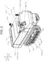
- FIG. 1 is a diagram illustrating a schematic configuration of a work vehicle 1 according to an embodiment of the present invention.
- the work vehicle 1 is used to perform work such as agricultural work and construction work.
- the work vehicle 1 includes a vehicle body 10 and a remote operation device 200 provided separately from the vehicle body 10.
- the remote operation device 200 (also referred to as a remote control device) enables an operator at a position away from the vehicle body 10 to operate the vehicle body 10. That is, the vehicle body 10 is remotely operated by the remote operation device 200.
- the configuration of the remote operation device 200 will be described below.
- the work vehicle 1 is configured to be capable of traveling even in automatic traveling. That is, the work vehicle 1 is configured to be switchable between traveling by a remote operation (also referred to as manual traveling) and automatic traveling.
- the automatic traveling means that, in the work vehicle 1, at least steering is autonomously (automatically) performed along a predetermined route (also referred to as a travel route).
- the automatic traveling may have a configuration in which, in addition to steering, for example, at least one of adjustment of the traveling speed and work by a work machine 12 to be described below is autonomously performed.
- the configuration of the work vehicle 1 is not limited to the above.
- the work vehicle 1 may be configured to be capable of traveling by a remote operation while excluding automatic traveling.
- the vehicle body 10 includes a traveling machine body 11 that travels on the ground, the work machine 12 that performs various types of work, and a hitch portion 13 that enables the work machine 12 to be connected to the traveling machine body 11. That is, the work vehicle 1 includes the traveling machine body 11, the work machine 12, and the hitch portion 13.
- directions used in the explanation are defined as follows.
- One side in one direction when the traveling machine body 11 travels straight along the one direction is referred to as “front,” and the other side is referred to as “back.”
- a side on which the hitch portion 13 is not arranged is referred to as "front”
- an opposite side is referred to as "back.”
- a left side and a right side from the back side toward the front side are defined as “left” and "right,” respectively.
- a gravity direction perpendicular to the front-back direction and the left-right direction is defined as an up-down direction
- an upstream side and a downstream side in the gravity direction are defined as "up” and “down,” respectively.
- the front side, the back side, the right side, the left side, the upside, and the downside are denoted by the symbols "F,” “B,” “R,” “L,” “U,” and “D,” respectively, as necessary.
- These directions are names merely used for the explanation and are not intended to limit the actual positional relationships and directions.
- the hitch portion 13 is configured to include a work machine drive device 111c to be described below.
- the work machine 12 is arranged behind the hitch portion 13. Therefore, the work machine 12 is arranged side by side in the front-back direction with respect to the traveling machine body 11. Moreover, the work machine 12 is attached to the traveling machine body 11 via the hitch portion 13 so as to be able to be lifted and lowered. That is, the work machine 12 is connected to the traveling machine body 11 by the hitch portion 13.
- the work machine 12 is attached to the hitch portion 13 so as to be replaceable. That is, various types of the work machines 12 can be attached.
- the work machine 12 is, for example, a tiller, a plow, a ridging device, a fertilizing device, an agricultural chemical spraying device, a harvesting device, a mowing device (also referred to as a cutting device), a snow removing device, or an earth removing device.
- a traveling direction of work may be a first direction DR1 or a second direction DR2 depending on the type of the work machine 12.
- the first direction DR1 is a direction from the work machine 12 toward the traveling machine body 11
- the second direction DR2 is a direction from the traveling machine body 11 toward the work machine 12 (refer to the dashed arrow in FIG. 1 ).
- the first direction DR1 corresponds to the front side of the traveling machine body 11
- the second direction DR2 corresponds to the back side of the traveling machine body 11.
- the work machine 12 is a snow removing device, that is, when a snow removing device is connected to the back side of the traveling machine body 11, work is performed while the work machine 12 is moved in the second direction DR2.
- the traveling machine body 11 moves backward
- the work performed while the work machine 12 is moved in the second direction DR2 is referred to as backward work.
- the work machine 12 is positioned closer to the traveling direction of the work (that is, the second direction DR2) than the traveling machine body 11. Therefore, the positional relationship between the traveling machine body 11 and the work machine 12 during work differs between the forward work and the backward work.
- the positional relationship between the traveling machine body 11 and the work machine 12 during work may vary depending on the type of the work machine 12.
- the type of the work machine 12 in which the backward work is performed is, for example, a mowing device or an earth removing device, in addition to a snow removing device.
- the traveling drive device 111b includes a drive source and a power transmission mechanism that transmits power from the drive source to the traveling portion 112.
- the drive source included in the traveling drive device 111b is an electric motor.
- the drive source included in the traveling drive device 111b may be other than the electric motor, and may be, for example, an engine.
- the state indication light 111f is arranged on the left front side of the upper surface of the machine body portion 111.
- the state indication light 111f is configured by stacking a plurality of indication lights.
- the state indication light 111f gives notice of the state of the work vehicle 1.
- the state indication light 111f gives notice of the state of communication between the traveling machine body 11 and the remote operation device 200.
- the first notification portion 111g1 is configured by a lamp using an incandescent lamp as a light source, but is not limited thereto.
- the first notification portion 111g1 may be configured by a lamp using an LED as a light source.
- the first notification portion 111g1 may be configured by a liquid crystal display device, an organic EL display device, or the like, and may give notice by various displays (for example, a graphic, a symbol, a character, or a combination thereof).
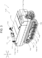
- the first notification portions 111g1 are provided on the front side and the back side of the machine body portion 111. More specifically, in particular, as illustrated in FIG. 2 , the first notification portions 111g1 are arranged on the left side and the right side on the front side of the machine body portion 111. In particular, as illustrated in FIG. 3 , the first notification portions 111g1 are arranged side by side in the left-right direction near the center in the left-right direction on the back side of the machine body portion 111.
- the arrangement positions of the first notification portions 111g1 are not limited to the above, and the first notification portions 111g1 may be arranged at positions easily visually recognized by the operator who is positioned away from the vehicle body 10.
- the first notification portions 111g1 may be arranged on the upper surface of the machine body portion 111.
- the number of the first notification portions 111g1 is not limited to the above.
- one first notification portion 111g1 may be provided on the front side of the machine body portion 111, and another first notification portion 111g1 may be provided on the back side of the machine body portion 111.
- the in-vehicle operation device 111h (refer to FIG. 2 ) is arranged on the inner front side covered by the outer cover 111a.
- the in-vehicle operation device 111h is configured to include an operation portion 300 that enables the setting related to the remote operation device 200. That is, the operation portion 300 is provided in the traveling machine body 11, and in particular, is provided at a position opposite to the side to which the work machine 12 is attached (back side). A setting to be performed using the operation portion 300 will be described below.
- the in-vehicle operation device 111h includes a key cylinder and a plurality of buttons (both not illustrated) in addition to the operation portion 300.
- a key not illustrated
- the power of the traveling machine body 11 can be turned on and off.
- the buttons are operated, the traveling machine body 11 travels without depending on the operation of the remote operation device 200. Accordingly, even when the wireless communication between the traveling machine body 11 and the remote operation device 200 is interrupted, the traveling machine body 11 can move (leave).
- the traveling portion 112 supports the machine body portion 111 such that the machine body portion 111 can travel.
- the traveling portion 112 includes a pair of left and right crawlers 112a.
- Each of the left and right crawlers 112a includes a track frame 112b extending in the front-back direction.
- Each track frame 112b is attached to the lower surface of the machine body portion 111.
- a driving sprocket 112c is arranged as a driving wheel at the front end of the track frame 112b. The power from the electric motor is transmitted to the driving sprocket 112c via the power transmission mechanism included in the traveling drive device 111b.
- the left and right crawlers 112a are driven by separate electric motors included in the traveling drive device 111b.
- the traveling portion 112 travels straight forward or backward. Whether the traveling portion 112 travels straight forward or backward depends on the rotation direction of the electric motors. For example, when the pair of left and right crawlers 112a are independently driven, the traveling portion 112 turns left or turns right.
- the crawler 112a has a configuration in which one driving wheel (driving sprocket 112c) and one driven wheel (driven sprocket 112d) are arranged side by side in the front-back direction and the crawler belt 112f is wound around the driving wheel and the driven wheel.
- the crawler may be of a type in which a crawler belt is wound around one driving wheel and two driven wheels in a triangular shape.
- the traveling portion 112 is of a crawler type, but may be of a type other than the crawler type, for example, a wheel type.
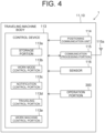
- FIG. 4 is a block diagram schematically illustrating the configuration related to the control of the work vehicle 1.
- components required to describe the features of the present embodiment are illustrated, and common components are not illustrated.
- the arithmetic device reads out the various types of programs from the storage portion 113a and executes arithmetic processing in accordance with the programs.
- the programs stored in the storage portion 113a may be provided by, for example, a computer-readable non-volatile recording medium.
- the programs may be provided from a program providing server via a communication line such as the Internet.
- control device 113 to act as a work mode control portion 113b, a notification control portion 113c, a traveling control portion 113d, and a work machine control portion 113e.
- the control device 113 may be configured by a single piece of hardware, or may be configured by a plurality of pieces of hardware that can communicate with each other.
- the functional portions 113b to 113e included in the control device 113 may be realized by causing the arithmetic device to execute arithmetic processing in accordance with the programs, that is, by software, but may be realized by another method.
- At least one of the functional portions 113b to 113e may be realized by using, for example, an application specific integrated circuit (ASIC), a field programmable gate array (FPGA), or the like. That is, at least one of the functional portions 113b to 113e may be realized by hardware using a dedicated IC or the like.
- at least one of the functional portions 113b to 113e may be realized by using both software and hardware.
- each of the functional portions 113b to 113e has a conceptual configuration. Therefore, a function executed by one component may be distributed to a plurality of components, or functions of a plurality of components may be integrated into one component.
- the work mode control portion 113b sets a work mode (forward work mode, backward work mode) on the basis of an instruction from the operation portion 300 (refer to FIG. 2 ). A setting of the work mode will be described below.
- the notification control portion 113c controls the notification portion 111g (first notification portion 111g1, second notification portion 111g2) on the basis of the setting of the work mode set by the work mode control portion 113b.
- the work machine control portion 113e adjusts a lifting-lowering position (a height from the ground) of the work machine 12 on the basis of a lifting-lowering instruction from the remote operation device 200. Moreover, the work machine control portion 113e controls the PTO power transmission portion to control switching of power transmission to the work machine 12 on the basis of a switching instruction from the remote operation device 200.
- the positioning communication unit 114 acquires the position of the vehicle body 10 as, for example, information of latitude and longitude by using a positioning signal received by the positioning antenna 111e (refer to FIG. 1 ) from a positioning satellite. For example, the positioning communication unit 114 receives a positioning signal from a reference station (not illustrated) by an appropriate method, and then performs positioning by using a known real time kinematic GNSS (RTK-GNSS) method. The positioning communication unit 114 outputs the positional information of the vehicle body 10 to the control device 113. The positioning communication unit 114 may perform positioning by using another method, for example, a differential GNSS (DGNSS) method.
- the work vehicle 1 may be configured to include, for example, a quantum compass capable of positioning, instead of or in addition to the positioning communication unit 114.
- the communication processing portion 115 performs communication with the remote operation device 200 via a communication antenna 115a.
- the communication antenna 115a is an antenna for performing wireless communication with the remote operation device 200.
- the wireless communication may be performed using a wireless local area network (LAN) such as Wi-Fi (registered mark).
- LAN wireless local area network
- the sensor 116 detects information related to the vehicle body 10 and outputs the detected information to the control device 113.
- the sensor 116 includes a plurality of types of sensors. Each of the plurality of types of sensors is connected to the control device 113 so as to be able to input a signal.
- the plurality of types of sensors include, for example, an inertial measurement unit, an obstacle sensor, a speed sensor, and a lifting-lowering position sensor.
- the inertial measurement unit is a device that includes a tri-axial angular velocity sensor and a tri-directional acceleration sensor and can measure the attitude of the traveling machine body 11.
- the obstacle sensor is a sensor that detects an obstacle existing around the vehicle body 10, and may be, for example, an ultrasonic sensor, a camera, a radar, or light detection and ranging (LiDAR).
- the speed sensor is a sensor that detects the traveling speed of the traveling machine body 11.
- the lifting-lowering position sensor is a sensor that detects the lifting-lowering position of the work machine 12.
- the work vehicle 1 may have a configuration in which automatic traveling is not performed.
- the positioning communication unit 114 and some of the sensors 116 may be removed. That is, the positioning communication unit 114 and some of the sensors 116 are not essential for the work vehicle 1 (vehicle body 10) to travel by a remote operation.
- the operation portion 300 is also connected to the control device 113. More specifically, the control device 113 provided in the traveling machine body 11 and the operation portion 300 are connected to each other using, for example, a connection cable (not illustrated). That is, the operation portion 300 is connected by wire to the control device 113. In a configuration in which the operation portion 300 is connected by wire to the control device 113, for example, a connection failure that occurs between the operation portion 300 and the control device 113 is reduced compared to a configuration in which the operation portion 300 is connected wirelessly to the control device 113.
- the operation portion 300 is connected wirelessly to the control device 113. Even in this configuration, as long as the operation portion 300 is provided in the traveling machine body 11, the distance of wireless communication is shortened, and the connection failure is reduced compared to, for example, a configuration in which the operation portion 300 is provided in the remote operation device 200, which will be described below.
- the following configuration is preferable from the viewpoint of reducing the connection failure between the operation portion 300 and a device provided in the traveling machine body 11 (for example, the control device 113) and reliably performing the setting related to the remote operation device 200. That is, as in the present embodiment, the operation portion 300 is preferably provided in the traveling machine body 11. In addition, when the operation portion 300 is provided in the traveling machine body 11, the operation portion 300 does not need to be provided in the remote operation device 200 that is a separate body from the traveling machine body 11, and the remote operation device 200 is configured to be small. Hereinafter, the configuration of the remote operation device 200 will be described.
- FIG. 5 is a plan view illustrating the configuration of the remote operation device 200.
- the remote operation device 200 includes a housing 201, a power switch 202, an antenna 203, an operation lever 204, a first operation switch 205, a second operation switch 206, an operation knob 207, and a display portion 208.
- the housing 201 configures a body portion of the remote operation device 200.
- the power switch 202, the antenna 203, the operation lever 204, the first operation switch 205, the second operation switch 206, the operation knob 207, and the display portion 208 described above are attached to appropriate positions of the housing 201.
- the arrangement illustrated in FIG. 5 is merely an example, and may be changed as appropriate.
- the power switch 202 is provided at the center of the front surface of the housing 201, and can turn on and off the power of the remote operation device 200.
- the power switch 202 is, for example, a seesaw switch.
- the power of the remote operation device 200 is, for example, a battery, a dry cell, or the like arranged in the housing 201.
- the antenna 203 is provided so as to protrude from a side surface (an upper side surface in FIG. 5 ) of the housing 201, and enables wireless communication with the traveling machine body 11.
- the remote operation device 200 can perform wireless communication with the traveling machine body 11.
- the power of the remote operation device 200 is turned off by the power switch 202, the remote operation device 200 cannot communicate with the traveling machine body 11.
- the traveling machine body 11 automatically stops traveling. That is, the power switch 202 has a function as an emergency stop switch of the traveling machine body 11.
- the emergency stop switch may be provided separately from the power switch 202.
- the operation lever 204 enables a traveling operation of the traveling machine body 11 and an operation of the work machine 12.
- the operation lever 204 has a first operation lever 204a and a second operation lever 204b arranged side by side with the power switch 202 interposed therebetween.
- the first operation lever 204a (the left lever illustrated in FIG. 5 ) can be tilted in at least two directions orthogonal to each other, which are indicated by the dashed arrows in FIG. 5 (an F204-B204 direction and an L204-R204 direction).
- the first operation lever 204a can also be tilted toward one side in the L204-R204 direction.
- the F204 direction is the upward direction
- the B204 direction is the downward direction
- the L204 direction is the leftward direction
- the R204 direction is the rightward direction.
- the second operation lever 204b (the right lever illustrated in FIG. 5 ) can also be tilted in the same directions as the first operation lever 204a.
- the first operation lever 204a and the second operation lever 204b fulfill different functions depending on whether the work mode is the forward work mode or the backward work mode.
- the functions of the first operation lever 204a and the second operation lever 204b will be described below.
- the first operation switch 205 is arranged on a side surface (an upper right side surface in FIG. 5 ) of the housing 201, and enables a plurality of types of settings related to automatic traveling.
- the plurality of types of settings include, for example, a start setting and an end setting of the automatic traveling.
- the first operation switch 205 is, for example, a momentary switch that can be pressed down.
- the second operation switch 206 is arranged on a side surface (an upper left side surface in FIG. 5 ) of the housing 201, and is switchable between a state where power transmission to the work machine 12 using the above-described PTO power transmission portion is enabled and a state where the power transmission to the work machine 12 is disabled.
- the second operation switch 206 is, for example, a toggle switch.
- the switching of the power transmission to the work machine 12 is performed by the work machine control portion 113e (refer to FIG. 4 ) controlling the PTO power transmission portion on the basis of the operation of the second operation switch 206 (switching instruction).
- the operation knob 207 is arranged on the front surface (an upper side of the front surface in FIG. 5 ) of the housing 201, and enables adjustment of the maximum speed of the traveling machine body 11. More specifically, two operation knobs 207 are provided. One of the two operation knobs 207 enables adjustment of the maximum speed of the traveling machine body 11 during straight traveling. The other of the two operation knobs 207 enables adjustment of the maximum speed of the traveling machine body 11 during turning traveling.
- the display portion 208 is arranged on the front surface (a lower side of the front surface in FIG. 5 ) of the housing 201, and displays various types of information to be notified to the operator.
- the various types of information include, for example, a display of a positional relationship between a travel route and the vehicle body 10 during automatic traveling.
- the display portion 208 is, for example, a liquid crystal display device, an organic EL display device, or the like.
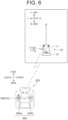
- FIG. 6 is an explanatory diagram for describing the forward work mode.
- tilting the first operation lever 204a of the remote operation device 200 in the F204 direction is referred to as a forward operation FO.
- the F204 direction is referred to as a forward operation direction DRf.
- Tilting the first operation lever 204a in the B204 direction is referred to as a backward operation.
- tilting the first operation lever 204a in the L204 direction is referred to as a left turning operation
- tilting the first operation lever 204a in the R204 direction is referred to as a right turning operation.
- the traveling machine body 11 When the forward operation FO is performed in the forward work mode, the traveling machine body 11 can be moved forward. That is, when the first operation lever 204a is tilted in the forward operation direction DRf, the traveling machine body 11 can travel in the first direction DR1. Therefore, in the forward work mode, the forward operation direction DRf corresponds to the first direction DR1, of the first direction DR1 and the second direction DR2.
- the traveling machine body 11 When the backward operation is performed in the forward work mode, the traveling machine body 11 can be moved backward. When the left turning operation is performed in the forward work mode, the traveling machine body 11 can be turned left. When the right turning operation is performed in the forward work mode, the traveling machine body 11 can be turned right.
- the work machine 12 can be lifted.
- the work machine 12 can be lowered.
- the traveling machine body 11 can be turned left.
- the traveling machine body 11 can be turned right.
- the turning radius when the operation is performed with the same operation amount differs between the turning (left turning, right turning) by the first operation lever 204a and the turning (left turning, right turning) by the second operation lever 204b. More specifically, when the first operation lever 204a and the second operation lever 204b are tilted by the same amount from the neutral position, the traveling machine body 11 can be turned with a larger turning radius when being operated by the second operation lever 204b than when being operated by the first operation lever 204a. In other words, the traveling machine body 11 can be gently turned by the second operation lever 204b.
- the first notification portions 111g1 on the front side are turned on (or blinked). Accordingly, the operator is notified that the traveling machine body 11 moves forward by the forward operation FO.
- the switching between turning on and off of the first notification portions 111g1 is performed by the notification control portion 113c (refer to FIG. 4 ).
- FIG. 7 is an explanatory diagram for describing the backward work mode.
- the definition of each operation of the forward operation FO, the backward operation, the left turning operation, and the right turning operation described above is the same.
- tilting the first operation lever 204a in the F204 direction is referred to as the forward operation FO, and the F204 direction is referred to as the forward operation direction DRf.
- the traveling machine body 11 When the forward operation FO is performed in the backward work mode, the traveling machine body 11 can be moved backward. That is, when the first operation lever 204a is tilted in the forward operation direction DRf, the traveling machine body 11 can travel in the second direction DR2. Therefore, in the backward work mode, the forward operation direction DRf corresponds to the second direction DR2, of the first direction DR1 and the second direction DR2.
- the traveling machine body 11 When the backward operation is performed in the backward work mode, the traveling machine body 11 can be moved forward. When the left turning operation is performed in the backward work mode, the traveling machine body 11 can be turned right. When the right turning operation is performed in the backward work mode, the traveling machine body 11 can be turned left. Therefore, when the first operation lever 204a is tilted in the same direction, the traveling direction of the traveling machine body 11 is reversed in the forward work mode and the backward work mode. In other words, the first operation lever 204a fulfills different functions in the forward work mode and the backward work mode.
- the work machine 12 can be lifted.
- the second operation lever 204b is tilted in the B204 direction in the backward work mode, the work machine 12 can be lowered. Therefore, for the operation of the second operation lever 204b in the F204 direction or the B204 direction, the same function is fulfilled in both the forward work mode and the backward work mode.
- the traveling machine body 11 When the second operation lever 204b is tilted in the L204 direction in the backward work mode, the traveling machine body 11 can be turned right. When the second operation lever 204b is tilted in the R204 direction in the backward work mode, the traveling machine body 11 can be turned left. Therefore, for the operation of the second operation lever 204b in the L204 direction or the R204 direction, the traveling direction of the traveling machine body 11 is reversed in the forward work mode and the backward work mode. In other words, different functions are fulfilled.
- the backward work mode is also the same in that the second operation lever 204b turns the traveling machine body 11 more gently than the first operation lever 204a.
- the first notification portions 111g1 on the back side are turned on (or blinked). Accordingly, the operator is notified that the traveling machine body 11 moves backward by the forward operation FO. Therefore, the first notification portions 111g1 give notice of the traveling direction of the traveling machine body 11 by the forward operation FO depending on whether the work mode is set to the forward work mode or the backward work mode.
- the traveling machine body 11 When the operator who is positioned away from the traveling machine body 11 views the first notification portions 111g1, the operator can easily confirm the traveling direction of the traveling machine body 11 by the forward operation FO. For example, the operator does not need to approach the traveling machine body 11 and confirm the information displayed on the operation portion 300 (touch panel). From this viewpoint, as in the present embodiment, the traveling machine body 11 preferably has the first notification portions 111g1 that give notice of the traveling direction of the traveling machine body 11 by the forward operation FO.
- the following configuration is preferable from the viewpoint of reliably realizing the configuration that gives notice of the traveling direction of the traveling machine body 11 by the forward operation FO when the traveling machine body 11 and the work machine 12 are arranged side by side in the front-back direction. That is, the first notification portions 111g1 are preferably provided on the front side and the back side of the traveling machine body 11.
- FIG. 8 is an explanatory diagram for describing the setting operation of the forward work mode.
- the setting of the forward work mode is performed by operating the operation portion 300. More details are as follows. As described above, the operation portion 300 is configured by a touch panel.
- the screen includes a work mode setting screen 301.
- the work mode setting screen 301 includes a forward work mode setting portion 302 and a backward work mode setting portion 303.
- the work mode When the operator operates (touches) the forward work mode setting portion 302 with a finger or the like, the work mode is set to the forward work mode.
- the setting of the work mode is performed by the work mode control portion 113b (refer to FIG. 4 ).
- a forward work mode display portion 304 included in the forward work mode setting portion 302 is turned on (or blinked).
- the forward work mode display portion 304 is turned off when the work mode is not the forward work mode, that is, when the work mode is the backward work mode.
- the backward work mode setting portion 303 and a backward work mode display portion 305 included in the backward work mode setting portion 303 will be described below.
- FIG. 9 is an explanatory diagram for describing the setting operation of the backward work mode.
- the setting of the backward work mode is performed by operating the operation portion 300. More specifically, when the operator operates (touches) the backward work mode setting portion 303 with a finger or the like, the work mode is set to the backward work mode. The setting of the work mode is performed by the work mode control portion 113b. When the work mode is set to the backward work mode, the backward work mode display portion 305 is turned on (or blinked). The backward work mode display portion 305 is turned off when the work mode is not the backward work mode, that is, when the work mode is the forward work mode. Accordingly, the work mode is set to either the forward work mode or the backward work mode by operating the operation portion 300. That is, the operation portion 300 is capable of setting the forward operation direction DRf to either the first direction DR1 or the second direction DR2.
- the operator can select which of the first direction DR1 and the second direction DR2 the forward operation direction DRf of the remote operation device 200 is set to. That is, regardless of the type of the work machine 12, the forward operation direction DRf can be made to correspond to the traveling direction of the work. Accordingly, the operator can perform operations without confusion, and erroneous operations can be reduced.
- the forward operation direction DRf corresponds to the traveling direction of the work, matters that require attention during operations are reduced, and a feeling of fatigue is lessened. Accordingly, a feeling of fatigue can be lessened, and erroneous operations can be reduced in remote operations.
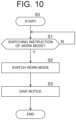
- FIG. 10 is a flowchart illustrating a flow of a switching setting of the work mode.
- step S0 it is assumed that the work mode is set to the forward work mode.
- step S1 the work mode control portion 113b (refer to FIG. 4 ) determines whether there is a switching instruction of the work mode.
- the switching instruction is realized by the operator operating (touching) the backward work mode setting portion 303 of the work mode setting screen 301 with a finger or the like (refer to FIG. 9 ).
- the processing proceeds to next step S2.
- the work mode control portion 113b continues the determination of a switching instruction.
- step S2 the work mode control portion 113b switches the work mode from the forward work mode to the backward work mode. Accordingly, the work mode is set to the backward work mode.
- the notification control portion 113c controls at least one of the first notification portion 111g1 and the second notification portion 111g2 (refer to FIG. 1 ) to give notice. That is, at least one of the first notification portion 111g1 and the second notification portion 111g2 gives notice when the setting of the work mode (the setting of the forward operation direction DRf) is switched.
- the notification control portion 113c rings only the second notification portion 111g2 (a speaker as auditory notifying means). However, instead of the second notification portion 111g2, the notification control portion 113c may blink (or turn on) the first notification portion 111g1 (a lamp as visual notifying means). In addition, the notification control portion 113c may blink (or turn on) the first notification portion 111g1 while ringing the second notification portion 111g2.
- step S0 the work mode may be set to the backward work mode.
- the work mode is switched from the backward work mode to the forward work mode by the switching setting.
- the switching instruction in this case is realized by operating the forward work mode setting portion 302 of the work mode setting screen 301 (refer to FIG. 8 ).
- notification is performed when the setting of the work mode, that is, the setting of the forward operation direction DRf is switched, and the operator reliably recognizes that the switching setting has been performed.
- appropriate notifying means is preferably used depending on the positional relationship between the work vehicle 1 and the operator, the work environment in which the work vehicle 1 is used, or the like.
- the traveling machine body 11 preferably has the second notification portion 111g2 that gives notice by means different from the first notification portion 111g1. At least one of the first notification portion 111g1 and the second notification portion 111g2 preferably gives notice when the setting of the forward operation direction DRf is switched.
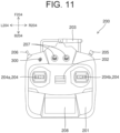
- FIG. 11 is a plan view illustrating the modification of the configuration of the remote operation device 200.
- the remote operation device 200 illustrated in FIG. 11 has the same configuration as that of the remote operation device 200 illustrated in FIG. 5 except that the operation portion 300 is included.
- the operation portion 300 is arranged on the front surface (an upper left side of the front surface in FIG. 11 ) of the housing 201.
- the operation portion 300 is configured by a momentary toggle switch, and can be tilted in the F204 direction or the B204 direction.
- the operation portion 300 is not limited to the above configuration, and may be configured by, for example, an alternate toggle switch, a dial, a lever, or the like.
- the display portion 208 may be configured to include a touch panel, and the display portion 208 may be used as the operation portion 300.
- the setting of the work mode is performed by operating the operation portion 300.
- the work mode is set to the forward work mode.
- the setting of the work mode is performed by the work mode control portion 113b (refer to FIG. 4 ). Accordingly, the forward operation direction DRf is set to the first direction DR1 (refer to FIG. 6 ).
- the forward operation direction DRf is set to the second direction DR2 (refer to FIG. 7 ).
- the forward operation direction DRf is set to either the first direction DR1 or the second direction DR2 by operating the operation portion 300. Therefore, from the viewpoint of setting the forward operation direction DRf even by the operator who is positioned away from the traveling machine body 11, as in the present modification, the operation portion 300 is preferably provided in the remote operation device 200. A configuration in which the operation portions 300 are provided in both the traveling machine body 11 and the remote operation device 200 may be adopted.
- the respective parts other than the machine body portion 111, that is, the traveling portion 112, the work machine 12, and the remote operation device 200 also have the same configurations as those of the respective parts illustrated in FIG. 1 and the like.
- the positioning antenna 111e, the state indication light 111f, the remote operation device 200, and the like are not illustrated.
- the driving portion 400 is provided in the upper part of the machine body portion 111.
- the driving portion 400 includes a driver's seat 401 and a steering portion 402.
- the driver's seat 401 is provided for the operator to sit on when the operator gets in the traveling machine body 11 and operates the traveling machine body 11.
- the driver's seat 401 is attached to the machine body portion 111 via a seat mount 401a.
- the seat mount 401a is fixed to the upper part of the machine body portion 111 and supports the driver's seat 401 from below.
- the seat mount 401a is configured by, for example, a box-shaped metallic member.
- the steering portion 402 is provided in front of the driver's seat 401 and enables a steering operation of the traveling machine body 11.
- a lever, a pedal, and the like to be operated by the operator are provided in the driving portion 400.
- the lever may include a plurality of types of levers, and may include, for example, a main speed change lever and an auxiliary speed change lever that enable adjustment of the maximum speed of the traveling machine body 11, a work machine operation lever that enables an operation of the work machine 12, and the like.
- the pedal may include a plurality of types of pedals, and may include, for example, an accelerator pedal and a brake pedal that enable acceleration and deceleration of the traveling machine body 11.
- the steering portion 402 is configured to include a steering wheel 403, a travel lever 404, an instrument panel 405, and a steering column 406.
- the steering wheel 403 is rotatably attached to the upper end portion of the steering column 406.
- the steering wheel 403 enables a steering operation of the traveling machine body 11.
- the configuration of the steering wheel 403 will be described below.
- a steering sensor (not illustrated) that detects the operation amount of the steering wheel 403 is provided inside the steering column 406.
- the steering sensor is configured by, for example, a potentiometer.
- the steering sensor is connected to the control device 113 (refer to FIG. 4 ), and outputs the detected operation amount of the steering wheel 403 to the control device 113.
- the arrangement position of the steering sensor is not limited to inside the steering column 406, and may be, for example, inside the machine body portion 111.
- the travel lever 404 is provided so as to protrude from the left side of the steering column 406.
- the travel lever 404 enables a traveling operation (forward operation, backward operation) of the traveling machine body 11.
- the instrument panel 405 is attached to the upper part of the steering column 406 via an attachment member (not illustrated).
- the instrument panel 405 is configured to include, for example, a liquid crystal display device, an organic EL display device, or the like, and displays a meter indicating the speed of the traveling machine body 11, or the like.
- the instrument panel 405 may be provided with a button for changing the type of information to be displayed, or the like.
- a base end portion (a portion on the side opposite to the side on which the steering wheel 403 is attached) of the steering column 406 is supported on the front portion of the machine body portion 111 so as to be rotatable about a rotation axis extending in the left-right direction.
- the steering column 406 rotates, the steering wheel 403, the travel lever 404, and the instrument panel 405 attached to the steering column 406 also rotate together with the steering column 406.
- the steering portion 402 is rotatably attached to the machine body portion 111.
- the position of the steering portion 402 can be changed between a getting-in operation position 402a (indicated by the solid line in FIG. 12 ) and a getting-out operation position 402b (indicated by the dashed line in FIG. 12 ).
- the steering portion 402 at the getting-in operation position 402a is positioned to protrude upward with respect to the machine body portion 111.
- the operator sits on the driver's seat 401 and operates the steering wheel 403 and the travel lever 404 included in the steering portion 402.
- the steering portion 402 at the getting-out operation position 402b is positioned to protrude forward with respect to the machine body portion 111.
- the operator gets out of the traveling machine body 11 and operates the steering wheel 403 and the travel lever 404. More specifically, the operator operates the steering wheel 403 and the travel lever 404 while facing backward on the front side of the traveling machine body 11 with respect to the steering portion 402 arranged at the getting-out operation position 402b.
- the position of the steering portion 402 may be changed to another position in addition to the getting-in operation position 402a and the getting-out operation position 402b.
- the position of the steering portion 402 may be changed to any position between the getting-in operation position 402a and the getting-out operation position 402b.
- the position of the steering portion 402 may be changed to a position below the getting-out operation position 402b.
- the turning direction of the traveling machine body 11 for the operation of the steering wheel 403 is different between when the steering portion 402 is arranged at the getting-in operation position 402a and when the steering portion 402 is arranged at the getting-out operation position 402b. Moreover, the direction of the meter or the like that the instrument panel 405 displays is also different. More details are as follows. First, a case where the steering portion 402 is arranged at the getting-in operation position 402a will be described with reference to FIG. 13.
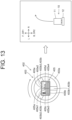
- FIG. 13 is an explanatory diagram for describing the steering operation when the steering portion 402 is arranged at the getting-in operation position 402a.
- FIG. 13 illustrates the steering wheel 403 and the instrument panel 405 as viewed from the operator who sits on the driver's seat 401, and the traveling state of the traveling machine body 11.
- a screen 405e of the instrument panel 405 illustrated in FIG. 13 is merely an example, and may be changed as appropriate.
- the steering wheel 403 is formed of, for example, a resin.
- the steering wheel 403 integrally has an annular wheel portion 403a and a spoke portion 403b extending from the wheel portion 403a toward the center side of the wheel portion 403a.
- the spoke portion 403b includes a first spoke portion 403b1, a second spoke portion 403b2, and a third spoke portion 403b3.
- the first spoke portion 403b1 extends from a lower side toward the center side of the wheel portion 403a.
- the second spoke portion 403b2 extends from an obliquely upper left side toward the center side of the wheel portion 403a.
- the third spoke portion 403b3 extends from an obliquely upper right side toward the center side of the wheel portion 403a.
- the above-described position is referred to as a neutral position.
- the traveling machine body 11 can travel straight without being turned.
- the spoke portion 403b is integrally formed with the wheel portion 403a, for example, when the operator holds and turns the wheel portion 403a, the spoke portion 403b is also rotationally moved.
- the configuration of the steering wheel 403 is not limited to the above.
- the steering wheel 403 may be configured to have an elliptical wheel portion.
- the number of the spoke portions 403b of the steering wheel 403 may be one, two, or four or more.
- the instrument panel 405 is arranged substantially at the center of the steering wheel 403.
- the instrument panel 405 has a rectangular shape, and is positioned with its longitudinal direction along the lateral direction. More specifically, in the instrument panel 405, an upper edge portion 405a is positioned on the upper side and a lower edge portion 405b is positioned on the lower side as viewed from the operator who sits on the driver's seat 401. Moreover, a left edge portion 405c is positioned on the left side, and a right edge portion 405d is positioned on the right side.
- the arrangement of the instrument panel 405 is not limited to the above.
- the instrument panel 405 may be positioned with its longitudinal direction along the vertical direction.
- the instrument panel 405 may be arranged so as to be shifted from the center of the steering wheel 403.
- the instrument panel 405 displays the screen (image) 405e in the following directions. That is, the instrument panel 405 displays the upper part of the screen 405e (upper left part 405e1, upper right part 405e2) on the upper side, and displays the lower part of the screen 405e (lower left part 405e3, lower right part 405e4) on the lower side as viewed from the operator. Moreover, the instrument panel 405 displays the left part of the screen 405e (upper left part 405e1, lower left part 405e3) on the left side, and displays the right part of the screen 405e (upper right part 405e2, lower right part 405e4) on the right side as viewed from the operator.
- the traveling machine body 11 can be moved forward by tilting the travel lever 404 (refer to FIG. 12 ) toward the front of the traveling machine body 11 (in the F direction in FIG. 12 ).
- the traveling machine body 11 can be moved backward by tilting the travel lever 404 toward the back of the traveling machine body 11 (in the B direction in FIG. 12 ).
- FIG. 14 is an explanatory diagram for describing the steering operation when the steering portion 402 is arranged at the getting-out operation position 402b.
- FIG. 14 illustrates the steering wheel 403 and the instrument panel 405 as viewed from the operator who faces backward on the front side of the traveling machine body 11 with respect to the steering portion 402 arranged at the getting-out operation position 402b.
- FIG. 14 also illustrates the traveling state of the traveling machine body 11.
- the screen 405e of the instrument panel 405 illustrated in FIG. 14 is also merely an example, and may be changed as appropriate.
- the instrument panel 405 also appears to be horizontally and vertically flipped compared to when the operator sits on the driver's seat 401 in the state where the steering portion 402 is arranged at the getting-in operation position 402a. That is, in the instrument panel 405, the upper edge portion 405a is positioned on the lower side and the lower edge portion 405b is positioned on the upper side as viewed from the operator who is positioned in front of the traveling machine body 11 with respect to the steering portion 402. Moreover, the left edge portion 405c is positioned on the right side, and the right edge portion 405d is positioned on the left side.
- the screen (image) 405e of the instrument panel 405 is displayed in the same direction as when the operator sits on the driver's seat 401 in the state where the steering portion 402 is arranged at the getting-in operation position 402a. That is, the instrument panel 405 displays the upper part of the screen 405e (upper left part 405e1, upper right part 405e2) on the upper side, and displays the lower part of the screen 405e (lower left part 405e3, lower right part 405e4) on the lower side as viewed from the operator.
- the instrument panel 405 displays the screen 405e with the screen 405e horizontally and vertically flipped compared to when the steering portion 402 is arranged at the getting-in operation position 402a. Accordingly, regardless of whether the steering portion 402 is arranged at the getting-in operation position 402a or the getting-out operation position 402b, the operator who operates the traveling machine body 11 with the steering wheel 403 can easily read the information (for example, the speed) on the screen 405e.
- the traveling machine body 11 can be turned left by turning the steering wheel 403 clockwise from the neutral position. More specifically, the traveling control portion 113d of the control device 113 controls the traveling drive device 111b on the basis of the steering amount of the steering wheel 403 detected by the steering sensor, so that the traveling machine body 11 is turned left.
- the traveling machine body 11 can be turned right by turning the steering wheel 403 counterclockwise from the neutral position.
- the traveling machine body 11 is turned right by turning the steering wheel 403 clockwise from the neutral position, and the traveling machine body 11 is turned left by turning the steering wheel 403 counterclockwise from the neutral position. Therefore, when the steering portion 402 is arranged at the getting-out operation position 402b, the turning direction of the traveling machine body 11 for the operation of the steering wheel 403 is inverted compared to when the steering portion 402 is arranged at the getting-in operation position 402a. More specifically, in the traveling control portion 113d, a setting of inverting the turning direction of the traveling machine body 11 is performed depending on whether the steering portion 402 is arranged at the getting-out operation position 402b.
- the operator who operates the traveling machine body 11 with the steering portion 402 can perform the same steering operation. That is, when the steering wheel 403 is turned clockwise, the traveling machine body 11 can be turned right as viewed from the operator. Moreover, when the steering wheel 403 is turned counterclockwise, the traveling machine body 11 can be turned left as viewed from the operator. Therefore, the operator can perform operations without confusion, and erroneous operations are reduced.
- the traveling machine body 11 can be moved forward by tilting the travel lever 404 (refer to FIG. 12 ) toward the front of the traveling machine body 11 (in the F direction in FIG. 12 ).
- the traveling machine body 11 can be moved backward by tilting the travel lever 404 toward the back of the traveling machine body 11 (in the B direction in FIG. 12 ). Accordingly, regardless of whether the steering portion 402 is arranged at the getting-in operation position 402a or the getting-out operation position 402b, the operator who operates the traveling machine body 11 with the steering portion 402 can perform the same traveling operation.
- the traveling machine body 11 can travel forward from the operator. Moreover, when the travel lever 404 is tilted to the front side as viewed from the operator, the traveling machine body 11 can travel backward from the operator.
- the work vehicle 1 described in the present embodiment can also be expressed as a work vehicle described in the following supplementary notes.
- a work vehicle of supplementary note (1) includes:
- a work vehicle of supplementary note (2) is characterized in that, in the work vehicle according to supplementary note (1), the traveling machine body has a first notification portion that gives notice of a traveling direction of the traveling machine body by the forward operation.
- a work vehicle of supplementary note (3) is characterized in that, in the work vehicle according to supplementary note (2),
- a work vehicle of supplementary note (4) is characterized in that, in the work vehicle according to supplementary note (2) or (3),
- a work vehicle of supplementary note (5) is characterized in that, in the work vehicle according to any one of supplementary notes (1) to (4), the operation portion is provided in the traveling machine body.
- a work vehicle of supplementary note (6) is characterized in that, in the work vehicle according to any one of supplementary notes (1) to (4), the operation portion is provided in the remote operation device.
- the present invention is applicable to a work vehicle such as an agricultural machine and a construction machine.
Landscapes
- Engineering & Computer Science (AREA)
- Life Sciences & Earth Sciences (AREA)
- Mechanical Engineering (AREA)
- General Engineering & Computer Science (AREA)
- Structural Engineering (AREA)
- Mining & Mineral Resources (AREA)
- Civil Engineering (AREA)
- Environmental Sciences (AREA)
- Soil Sciences (AREA)
- Aviation & Aerospace Engineering (AREA)
- Radar, Positioning & Navigation (AREA)
- Remote Sensing (AREA)
- Physics & Mathematics (AREA)
- General Physics & Mathematics (AREA)
- Automation & Control Theory (AREA)
- Human Computer Interaction (AREA)
- Guiding Agricultural Machines (AREA)
Applications Claiming Priority (1)
| Application Number | Priority Date | Filing Date | Title |
|---|---|---|---|
| JP2023211024A JP2025095181A (ja) | 2023-12-14 | 2023-12-14 | 作業車両 |
Publications (1)
| Publication Number | Publication Date |
|---|---|
| EP4573864A1 true EP4573864A1 (fr) | 2025-06-25 |
Family
ID=93742682
Family Applications (1)
| Application Number | Title | Priority Date | Filing Date |
|---|---|---|---|
| EP24216430.9A Pending EP4573864A1 (fr) | 2023-12-14 | 2024-11-29 | Véhicule de travail |
Country Status (5)
| Country | Link |
|---|---|
| US (1) | US20250194452A1 (fr) |
| EP (1) | EP4573864A1 (fr) |
| JP (1) | JP2025095181A (fr) |
| KR (1) | KR20250092086A (fr) |
| CN (1) | CN120153795A (fr) |
Cited By (1)
| Publication number | Priority date | Publication date | Assignee | Title |
|---|---|---|---|---|
| EP4699432A1 (fr) * | 2024-03-08 | 2026-02-25 | Yanmar Holdings Co., Ltd. | Véhicule de travail |
Citations (6)
| Publication number | Priority date | Publication date | Assignee | Title |
|---|---|---|---|---|
| US5092422A (en) * | 1989-12-12 | 1992-03-03 | Clemson University | Multipurpose agricultural tractor |
| EP2846209A2 (fr) * | 2013-09-04 | 2015-03-11 | CLAAS Tractor S.A.S. | Procédé de commande externe d'un véhicule utilitaire agricole |
| JP2015168395A (ja) | 2014-03-10 | 2015-09-28 | 株式会社クボタ | 作業機 |
| US10802496B2 (en) * | 2018-08-28 | 2020-10-13 | Deere & Company | Remote tractor control system |
| US20220001942A1 (en) * | 2018-10-29 | 2022-01-06 | Yanmar Power Technology Co., Ltd. | Traveling Vehicle |
| WO2023199581A1 (fr) * | 2022-04-13 | 2023-10-19 | 株式会社やまびこ | Système de machine de travail mobile sans pilote |
Family Cites Families (2)
| Publication number | Priority date | Publication date | Assignee | Title |
|---|---|---|---|---|
| US9050890B2 (en) * | 2013-08-15 | 2015-06-09 | Deere & Company | Vehicle positioning system |
| TW201900459A (zh) * | 2017-05-17 | 2019-01-01 | 大陸商上海蔚蘭動力科技有限公司 | 駕駛意圖指示裝置及方法 |
-
2023
- 2023-12-14 JP JP2023211024A patent/JP2025095181A/ja active Pending
-
2024
- 2024-11-29 EP EP24216430.9A patent/EP4573864A1/fr active Pending
- 2024-12-05 CN CN202411777533.0A patent/CN120153795A/zh active Pending
- 2024-12-09 KR KR1020240181715A patent/KR20250092086A/ko active Pending
- 2024-12-13 US US18/980,994 patent/US20250194452A1/en active Pending
Patent Citations (7)
| Publication number | Priority date | Publication date | Assignee | Title |
|---|---|---|---|---|
| US5092422A (en) * | 1989-12-12 | 1992-03-03 | Clemson University | Multipurpose agricultural tractor |
| EP2846209A2 (fr) * | 2013-09-04 | 2015-03-11 | CLAAS Tractor S.A.S. | Procédé de commande externe d'un véhicule utilitaire agricole |
| JP2015168395A (ja) | 2014-03-10 | 2015-09-28 | 株式会社クボタ | 作業機 |
| US10802496B2 (en) * | 2018-08-28 | 2020-10-13 | Deere & Company | Remote tractor control system |
| US20220001942A1 (en) * | 2018-10-29 | 2022-01-06 | Yanmar Power Technology Co., Ltd. | Traveling Vehicle |
| WO2023199581A1 (fr) * | 2022-04-13 | 2023-10-19 | 株式会社やまびこ | Système de machine de travail mobile sans pilote |
| EP4505855A1 (fr) * | 2022-04-13 | 2025-02-12 | Yamabiko Corporation | Système de machine de travail mobile sans pilote |
Cited By (1)
| Publication number | Priority date | Publication date | Assignee | Title |
|---|---|---|---|---|
| EP4699432A1 (fr) * | 2024-03-08 | 2026-02-25 | Yanmar Holdings Co., Ltd. | Véhicule de travail |
Also Published As
| Publication number | Publication date |
|---|---|
| JP2025095181A (ja) | 2025-06-26 |
| CN120153795A (zh) | 2025-06-17 |
| KR20250092086A (ko) | 2025-06-23 |
| US20250194452A1 (en) | 2025-06-19 |
Similar Documents
| Publication | Publication Date | Title |
|---|---|---|
| US11231708B2 (en) | Display control apparatus, display control method, and storage medium | |
| EP3970462A1 (fr) | Système de déplacement autonome | |
| EP4573864A1 (fr) | Véhicule de travail | |
| JP7714714B2 (ja) | 自動走行システム及び自動走行方法 | |
| JP2024054304A (ja) | 作業車両の支援システム及び作業車両の支援方法 | |
| JP2022097701A (ja) | 作業車両 | |
| CN112040762A (zh) | 田地作业车 | |
| WO2020174839A1 (fr) | Système de déplacement autonome | |
| JP4650247B2 (ja) | カーナビゲーションシステム | |
| JP2020000023A (ja) | 作業車両 | |
| CN111988982B (zh) | 作业车 | |
| JP2025133862A (ja) | 走行制御方法、走行制御システム、作業車両、及び走行制御プログラム | |
| US20250282218A1 (en) | Work vehicle | |
| JP2020054316A (ja) | 作業車両 | |
| US20250284277A1 (en) | Work vehicle, automated traveling method, and program | |
| US20250194460A1 (en) | Work vehicle | |
| JP2025095180A (ja) | 操作装置及び作業車両 | |
| JP7809578B2 (ja) | 自動走行システム | |
| JP2025095178A (ja) | 操作装置及び作業車両 | |
| JP7849257B2 (ja) | 走行制御方法、走行制御システム、及び走行制御プログラム | |
| JP2025096143A (ja) | 自動走行方法、自動走行システム、および、プログラム | |
| JP2024004952A (ja) | 自動走行作業方法、自動走行作業システム、および、プログラム | |
| KR20250092072A (ko) | 자동 주행 방법, 자동 주행 시스템, 및 프로그램 | |
| JP2025095186A (ja) | 操作支援方法、操作支援システム、および、プログラム | |
| JP2025160591A (ja) | 作業車両の自動走行方法、自動走行システム、および自動走行プログラム |
Legal Events
| Date | Code | Title | Description |
|---|---|---|---|
| PUAI | Public reference made under article 153(3) epc to a published international application that has entered the european phase |
Free format text: ORIGINAL CODE: 0009012 |
|
| STAA | Information on the status of an ep patent application or granted ep patent |
Free format text: STATUS: THE APPLICATION HAS BEEN PUBLISHED |
|
| AK | Designated contracting states |
Kind code of ref document: A1 Designated state(s): AL AT BE BG CH CY CZ DE DK EE ES FI FR GB GR HR HU IE IS IT LI LT LU LV MC ME MK MT NL NO PL PT RO RS SE SI SK SM TR |
|
| STAA | Information on the status of an ep patent application or granted ep patent |
Free format text: STATUS: REQUEST FOR EXAMINATION WAS MADE |
|
| 17P | Request for examination filed |
Effective date: 20251217 |