EP4573970A2 - Canapé modulaire - Google Patents
Canapé modulaire Download PDFInfo
- Publication number
- EP4573970A2 EP4573970A2 EP24209932.3A EP24209932A EP4573970A2 EP 4573970 A2 EP4573970 A2 EP 4573970A2 EP 24209932 A EP24209932 A EP 24209932A EP 4573970 A2 EP4573970 A2 EP 4573970A2
- Authority
- EP
- European Patent Office
- Prior art keywords
- seat
- seat part
- feet
- parts
- underside
- Prior art date
- Legal status (The legal status is an assumption and is not a legal conclusion. Google has not performed a legal analysis and makes no representation as to the accuracy of the status listed.)
- Pending
Links
Images


Classifications
-
- A—HUMAN NECESSITIES
- A47—FURNITURE; DOMESTIC ARTICLES OR APPLIANCES; COFFEE MILLS; SPICE MILLS; SUCTION CLEANERS IN GENERAL
- A47C—CHAIRS; SOFAS; BEDS
- A47C13/00—Convertible chairs, stools or benches
- A47C13/005—Modular seating
-
- A—HUMAN NECESSITIES
- A47—FURNITURE; DOMESTIC ARTICLES OR APPLIANCES; COFFEE MILLS; SPICE MILLS; SUCTION CLEANERS IN GENERAL
- A47C—CHAIRS; SOFAS; BEDS
- A47C31/00—Details or accessories for chairs, beds, or the like, not provided for in other groups of this subclass, e.g. upholstery fasteners, mattress protectors, stretching devices for mattress nets
- A47C31/10—Loose or removable furniture covers
-
- A—HUMAN NECESSITIES
- A47—FURNITURE; DOMESTIC ARTICLES OR APPLIANCES; COFFEE MILLS; SPICE MILLS; SUCTION CLEANERS IN GENERAL
- A47C—CHAIRS; SOFAS; BEDS
- A47C4/00—Foldable, collapsible or dismountable chairs
- A47C4/02—Dismountable chairs
- A47C4/028—Upholstered chairs, e.g. metal, plastic or wooden chairs
Definitions
- the invention relates to a modular sofa having the features of the preamble of claim 1.
- the patent EP 1 893 053 B1 discloses a modular sofa with detachably connected seat parts and back and side parts detachably connected to the seat parts.
- the seat parts, back parts, and side parts have box-shaped base parts with cushions over which slip covers are pulled.
- the box-shaped base parts of the seat parts have intermediate shelves at a mid-height of the base parts, which are framed on all sides by upright walls such that the base parts have open cavities at the top and bottom.
- Cushions are placed in the open cavities of the base parts of the seat parts of the known modular sofa, onto which another cushion is placed, over which the slip covers are pulled up to a lower edge of the box-shaped base parts, which hold the upper cushions on the base parts.
- the object of the invention is to provide a simple way of fastening a cover to a seat part, back part and/or side part of a modular sofa of the above type
- the cover should be able to be attached and removed from the seat, back, and/or side panels by hand without the need for tools.
- the sofa according to the invention has a modular design, comprising a seat and a backrest, and in some embodiments of the invention, an additional side section. Multiple seat sections, backrests, and/or side sections can also be combined and connected to form a sofa.
- a slipcover-like, for example padded, cover can be pulled over the seat part, the back part and/or the side part.
- Spatial directions such as “down” and “up” refer to the intended placement of the seating section or sofa with its feet resting on the floor or another, particularly horizontal, surface.
- the floor, or the surface in general, is located at the bottom of the sofa.
- the cover can be removed from the seat, back and/or side parts and pulled upwards.
- the cover does not have to extend all the way down on all sides; it is sufficient if the cover extends down on, for example, only three sides or two opposite sides of the seat part, back part and/or side part.
- the cover does not have to extend all the way down on the back of the back part or on sides of the seat part, back part and/or side part facing another seat part, back part or side part.
- the cover preferably extends down on all sides of the seat part, back part and/or side part, is preferably folded over on all sides into the hollow space in the seat part, back part and/or side part that is open at the bottom, and is preferably removably secured in the hollow space on all sides - preferably by hand without tools.
- the cover can be manually attached and removed without tools in the open-bottomed cavity on the underside of the seat, back, and/or side panels.
- the cover is releasably attached to an inner side of a border of the open-bottomed cavity on the underside of the seat, back, and/or side panels using hook-and-loop fasteners, or is hung on hooks or the like.
- One advantage of the invention is the possibility of producing its individual components, such as covers, upholstery, bases, etc., in a single, single-material manner. After disassembling the sofa, the individual parts can be easily recycled or disposed of.
- the back and side panels can be identical in embodiments of the invention, resulting in a modular sofa according to the invention with fewer different components.
- the back panel can also be used as a side panel.
- different back and side panels are also possible.
- the side panels are lower than the back panels.
- the cover has a loop on a lower edge, which is folded over at the bottom of the seat part, back part and/or side part of the modular sofa from the outside inwards into the hollow space of the seat part, back part and/or side part, which is open at the bottom, and then upwards into the hollow space.
- a threading rod is or is pulled through the loop on the folded-over lower edge of the cover and is secured to an inner side of a border of the hollow space open at the bottom on the underside of the seat part, back part and/or side part, for example, hooked onto pins or hooks.
- the threading rod can be a metal rod, a plastic rod, also made of fiber-reinforced plastic, a wooden rod, or a rod made of another material.
- the loop consists in particular of a flexible, two-dimensional sheet material and preferably extends along the lower edge of the cover and is only interrupted at the pins or hooks into which the threading rod is or will be hooked.
- the cover has a loop or loops between the pins or hooks interrupted at the pins or hooks on opposite sides or on all sides of the seat part and on opposite sides of the back part and/or the side part.
- a threading rod is inserted through the loop(s) of the cover and hooked onto the pins, hooks or the like on the inside of the enclosure of the hollow space.
- thread rods can be arranged one behind the other in the loops of the cover, whereby the ends of the thread rods can overlap, butt against each other or be spaced apart from each other.
- a preferred embodiment of the invention provides that the seat part, the back part, and/or the side part has a box-shaped base part that provides stability to the seat part, back part, and/or side part.
- the base part has an intermediate floor and upright walls that support the intermediate floor in the manner of a frame or socket. enclose.
- standing is meant that the walls of the base part are vertical or approximately vertical when the sofa is placed on the floor or the support surface as intended, with its underside facing the floor or, in general, the support surface, or that the walls are perpendicular or approximately perpendicular to the intermediate floor of the base part.
- the walls of the base part project upwards and/or downwards over the intermediate floor in such a way that a hollow space open at the top and bottom is formed on and below the intermediate floor.
- the hollow space open at the bottom under the intermediate floor of the base part forms the hollow space open at the bottom of the seat part of the modular sofa according to the invention.
- the box-shaped base part of the back part and/or the side part of the modular sofa according to the invention in embodiments of the invention, has similar hollow spaces open at the bottom on their undersides.
- the walls of the base section, which protrude downwards above the intermediate floor, form the enclosure of the hollow space open at the bottom.
- the covers are removably secured to their inner sides, for example, by threading rods inserted through the loops at the lower edge of the cover.
- the base section is unpainted to facilitate separate disposal; no staples, screws, or nails are used; and the cover-like upholstery covers and the covers do not have zippers, snap fasteners, eyelets, or the like that would have to be removed prior to separate disposal or recycling.
- box-shaped base part is in particular cuboid-shaped, other shapes, such as round, are also possible.
- the walls of the box-shaped base part protrude in particular at right angles upwards and/or downwards from the intermediate floor.
- Angular, polygonal walls are not essential for the invention; the base part can, for example, also have a circumferential, cylindrical or otherwise round wall that protrudes at a right angle or another angle downwards and/or upwards from the intermediate floor.
- the wall can, for example, also be in the shape of a single-shell hyperboloid, and in principle the wall or the box-shaped base part can have any desired shape, provided that the downwardly open cavity for folding the cover from the outside into the cavity in which the cover is fixed exists on the underside.
- the box-shaped base part has a cuboid shape as described above.
- the seat part has a seat at the top and feet on the underside, with which the seat part can be placed on a surface such as a floor.
- the "underside” faces the floor or other surface, and a “top side” faces away from the floor or other surface when the seat part or sofa is positioned as intended with its feet resting on the floor or other surface.
- a “seat” here refers to an element or upper surface of the seat part that is designed and intended for a person to sit on.
- the top side of the seat part has a seating surface for the person to sit on. If the seat part has the box-shaped base part, the feet of the seat part are arranged, in particular, on the underside of the intermediate floor, projecting downwards from the intermediate floor.
- the underside of the intermediate floor faces the floor or generally the surface, and the top side of the intermediate floor faces away from the floor or generally the surface when the sofa or seat part is positioned as intended with its feet resting on the floor or generally the surface.
- the back part of the modular sofa according to the invention is or is arranged on a rear side of the seat part, whereby the "rear side” here refers to the side of the seat part on which the back part is or is arranged.
- the back part has a backrest on a front side, whereby the “front side” here refers to the side of the back part facing the seat part.
- the backrest is a surface intended for leaning the back of the person sitting on the sofa or on the seat part of the sofa, which surface is usually vertical or at an acute angle to a vertical on the rear of the seat part upwards from the top of the seat part.
- seat sections and back sections can also be connected to form the modular sofa according to the invention by means of a detachable and rigid connection of their feet, thus enabling, for example, a wider sofa and/or a corner sofa or a U-shaped sofa.
- the seat surface can also be extended by arranging an additional seat section at a front side opposite the back of one seat section and away from the back section.
- One embodiment of the invention has a side part that is or will be arranged on a side of the seat part that is adjacent to the back of the seat part, which is referred to here as the side edge.
- the side part projects upwards beyond the top of the seat part that forms the seat surface, and the side part has feet on its underside that are or will be rigidly and detachably connected to feet of the seat part and/or the back part such that the side part is connected to the seat part and/or the back part via the interconnected feet.
- the seat parts are not rigidly connected to one another at their feet, but rather the seat parts are connected with connectors that are only attached or connected to a seat part after the seat parts have been set up.
- the back parts and side parts can be attached to the seat parts and individual seat parts can be set up with the back parts and side parts attached to them, i.e. placed with their feet on the floor or the surface in general. It is therefore not necessary to set up the sofa as a whole.
- the set-up seat parts are pushed together on the floor or the surface in general as they are intended to be a sofa and connected with the connectors. A tensile-resistant connection of the seat parts is sufficient to prevent the seat parts from shifting against one another.
- the slipcover covers or spans and secures the upholstery to the seat, back, and/or side panels.
- the slipcover allows for easy attachment of the upholstery to the seat, back, and/or side panels. Furthermore, the slipcover determines the look and color of the sofa.
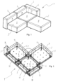
- Figure 3 shows box-shaped base parts 5, 16 with feet 12 of a seat part 1, a back part 3 and a side part 4 of the modular sofa 1 diagonally from below.
- the box-shaped base part 5 of the seat parts 2 is in Figure 4 Shown in an exploded view: it has a square or rectangular plate as an intermediate floor 6, which has walls 7 on all four sides that enclose the intermediate floor 6 in the manner of a square or rectangular frame.
- the walls 7 are arranged perpendicular to one another and perpendicular to the intermediate floor 6 and protrude from the intermediate floor 6 on both sides, i.e., upwards and downwards.
- the box-shaped base part 5 of the seat parts 2 of the sofa 1 according to the invention has an upper cavity within the walls 7 on an upper side of the intermediate floor 6 and a lower cavity 10 within the walls 7 on a lower side 11 of the intermediate floor 6.
- the upper cavity is open upwards and the lower cavity 10 is open downwards.
- the walls 7 form an enclosure 28 of the cavities 10 above and below the intermediate floor 6 of the box-shaped base part 5.
- feet 12 are arranged, which project downwards over the frame-like walls 7 of the box-shaped base part 5 (compare also Figures 2 and 3 ).
- the seat part 2 or the sofa 1 is placed on a floor (not shown) or generally on a support surface such that its feet 12 rest on the floor or generally on the support surface.
- the feet 12 are arranged close to the sides of the seat part 2, i.e., close to the walls 7 of the box-shaped base part 5, such that the seat part 2 stands stably and securely with its feet 12 on the floor or generally on the support surface.
- the seat part 2 can therefore also be considered freestanding.
- the seat part 2 has four feet 12 arranged at the corners of an imaginary square or rectangle, the sides of which are arranged parallel to the walls 7 of the box-shaped base part 5 of the seat part 2 and slightly offset inward from the walls 7 on the underside 11 of the intermediate floor 6.
- the arrangement of the feet 12 is not mandatory; it is important or at least advantageous to arrange the feet 12 close to the edge so that the seat part 2 stands securely on the feet 12.
- the underside 11 of the intermediate floor 6 and the seat part 2 refers here to the side on which the feet 12 are arranged and which face the floor or generally the support surface when the seat part 2 or the sofa 1 is placed on the floor or generally the support surface, as intended, with its feet 12 resting on the floor or generally on the support surface.
- the top side 8 is accordingly the opposite side, facing away from the floor or generally the support surface.
- the “bottom” refers to the side facing the floor or generally the support surface
- the “top” refers to the side facing away from the floor or generally the support surface when the seat part 2 or the sofa 1 is placed on the floor or generally the support surface, as intended, with its feet 12 resting on the floor or generally on the support surface.
- a cuboid-shaped cushion 13 is arranged, the outer sides of which are flush with the outer sides of the walls 7 of the box-shaped base part 5.
- the outer sides of the cushion 13 have recesses which are as wide as the walls 7 of the box-shaped base part 5 are thick, such that the cushion 13 engages in the upper cavity of the box-shaped base part 5 between the four walls 7 and is thereby held against lateral displacement, i.e. against displacement parallel to the intermediate floor 6 in all directions (see also Figure 5 ).
- the cushion 13 is higher than the upper cavity of the box-shaped base part 5 of the seat part 2 from the upper edges of the walls 7 to the intermediate floor 6 is deep such that the cushion 13 projects upwards over the walls 7 of the box-shaped base part 5 when the cushion 13 lies between the walls 7 on the intermediate floor 6 of the box-shaped base part 5.
- the spring base can, for example, also be a cushion such as the cushion 13, in whose cavity 14 on the underside the spring base 15 is arranged.
- the base spring 15 preferably has a different spring or cushion hardness than the cushion 13.
- the base spring 15 rests on the intermediate floor 6 of the box-shaped base part 5 of the seat part 2 and is as high as the cavity 14 in the underside of the cushion 13 made of foam such that the cushion 13 made of foam rests on the base spring 15.
- standing is meant that the base part 16 of the back part 3 and the side part 4 is higher than it is deep.
- deep is meant a dimension of the back part 3 and the side part 4 perpendicular to a side of the seat part 2 on which the back part 3 or the side part 4 is arranged.
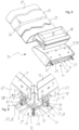
- Figure 6 shows individual parts of the back part 3, with the side part 4 being constructed identically.
- the base part 16 of the back part 3 has a cavity 17 above the upper side 8 of the cushion 13 of the seat part 2, which is open on a front side of the back part 3 facing the seat part 2.
- a back cushion 18 is arranged in the cavity 17 of the back part 3 and protrudes from the back part 3.
- a front side of the back cushion 18 facing the seat part 2 forms a backrest 19 against which a person sitting on the cushion 13 of the seat part 2 can lean.
- the base part 16 of the side part 4 like the base part 16 of the back part 3, has a hollow space 17 above the upper side 8 of the cushion 13 of the seat part 2, which is open on an inner side of the side part 3 facing the seat part 2.
- a cushion of the side part 4 has the same structure as the back part 3, can be considered a side cushion, and is located on the side of the side part 4 facing the seat part 2, which is referred to here as the inner side.
- the base part 16 of the back part 3 and the side part 4 has feet 12, which in the exemplary embodiment are arranged in an imaginary vertical center plane or a plane parallel to the center plane of the base part 16 of the back part 3 and the side part 4. Due to the arrangement of the feet 12 in one plane, the back part 3 and the side part 4 do not stand stably with their feet 12 on the floor or the support surface in general, but are very likely to fall over, i.e. the back part 3 and the side part 4 are not self-supporting on their own.
- the back parts 3 and the side part 4 are identical in construction, i.e. there is no difference between the back part 3 and the side part 4, but a back part 3 is arranged as a side part 4 on the side of a seat part 2 and is connected to this and preferably, as described, also to the back part 3 on the back of the seat part 2.
- FIG. 1 shows the connections of a seat part 2, a back part 3 and a side part 4.
- FIG. 3 shows the connections of a seat part 2, a back part 3 and a side part 4.
- two feet 12 each or for connecting a seat part 2 with a back part 3 and a side part 4 as in Figure 3
- three feet 12 are connected to each other "at an angle" by a strut 20.
- the strut 20 has two rods 21 that are arranged parallel to each other and horizontally, i.e., parallel to the intermediate floor of the seat section between the two feet 12, and are screwed to the feet 12.
- the strut 20 connects the feet 12 rigidly and detachably. With the strut 20, the two feet 12 form a kind of flat ladder frame. Other connections, for example, with a different strut or, for example, a plate-shaped stiffener between the feet 12, are possible. (not shown).
- the feet 12 are detachably connected to one another so that the seat part(s) 2, back part(s) 3, and side part(s) 4 of the modular sofa 1 according to the invention can be detached from one another and connected to one another in basically any desired combination.
- a wrench such as an open-end wrench, ring wrench, or Allen key is required. It is also possible to connect and detach the two feet 12 to the strut 20 or extension without tools, for example, using bayonet locks, hand levers, wing-head nuts, wing-head screws, or star-grip screws.
- Two feet 12 on each side of a seat part 2 are connected to the two feet 12 of a back part 3 or a side part 4, or one foot 12 of a seat part 2 is connected to one foot 12 of a back part 3 or a side part 4, the other foot 12 of which is connected to one foot 12 of another back part 3 or side part 4 or seat part 2.
- the seat parts 2 After connecting the back parts 3 and the side parts 4, the seat parts 2 are set up, i.e. placed on the floor or other surface with the feet 12. The seat parts 2 are then pushed together as they are to form the sofa 1 and connected with clamp-like connectors 29, as shown in the detailed illustration in Figure 8 shows.
- Figure 8 shows an inside corner between three seat sections 2 of a corner sofa, viewed diagonally from below.
- the connectors 19 are Z-shaped.
- One leg of the connector 29 is attached, for example, by screwing, to a foot 12 of a seat section 2 of the sofa 1.
- Another leg 30 of the connector 29 extends upwards to the side of the seat section 2.
- the connector 29 is preferably attached before the seat section 2 is placed on its feet 12.
- an adjacent seat part 2 is placed on the connector 29 such that one of the walls 7 of the box-shaped base part 5 overlaps the upwardly projecting leg 30 of the connector 29, whereby the two seat parts 2 are connected to each other with their sides resting against each other in a tensile-resistant manner.
- Lateral slopes 31 on the upwardly projecting legs 30 of the connectors 29 align the seat parts 2 with each other when connected.
- a slipcover-like upholstery cover 22 and, above this, a slipcover 23 are pulled over the seat parts 2, back parts 3, and side parts 4 of the modular sofa 1 according to the invention.
- the upholstery covers 22 extend down the sides of the box-shaped base parts 5, 16 of the seat parts 2, back parts 3, and side parts 4 to the lower edges of the box-shaped base parts 5, 16 and also cover the upholstery 13.
- the slipcovers 23 are made, for example, of fabric, leather, or plastic, for example of a nonwoven fabric containing microfibers.
- the slipcover-like upholstery covers 22 and the slipcovers 23 can be pulled over the base parts 5, 16 and the cushions 13, 14, 18 of the seat parts 2, back parts 3, and side parts 4, even when the base parts 5, 16 are connected.
- the upholstery covers 22 and the slipcovers 23 can be pulled off the connected seat parts 2, back parts 3, and side parts 5 and pulled back on.
- the threading rods 25 must be unhooked from the pins 26 in the hollow spaces 10 of the box-shaped base parts 10, which are open at the bottom, or the threading rods 25 must be pulled out of the loops 24 of the slipcovers 23.
- the covers 23 are coverings which, like the upholstery covers 22, are pulled from above over the box-shaped base parts 5, 16 of the seat parts 2, back parts 3 and side parts 4, cover the upholstery 13 and are fastened to the lower edges of the box-shaped base parts 5, 16 as in Figure 4 can be seen folded inwards and upwards again.
- the covers 23 have loops 24 on their lower edges, which are folded inwards and upwards again on the insides 27 of the walls 7 of the box-shaped base parts 5, 16 of the seat parts 2, back parts 3 and side parts 4.
- the walls 7 of the box-shaped base parts 5, 16 form enclosures 28 of the lower hollow spaces 10 of the box-shaped base parts 5, 16 of the seat parts 2, back parts 3 and side parts 4 of the modular sofa 1 according to the invention, which are open at the bottom.
- Threading rods 25 are or will be inserted through the loops 24 and are or will be hooked onto pins 26 or hooks inside at the bottom of the walls 7 or enclosures 28 of the lower hollow spaces 10 of the box-shaped base parts 5 of the seat parts 2, back parts 3 and side parts 4 of the modular sofa 1, whereby the covers 23 are detachably attached to the seat parts 2, back parts 3 and side parts 4.
- the loops 24 are flexible flat structures that extend along the folded lower edges of the covers 23 on the inner sides 27 of the surrounds 28 of the lower cavities 10 of the base parts 5, 16 of the seat parts 2, back parts 3, and side parts 4, and are interrupted only in the area of the pins 26 or hooks to which the threading rods 25 are attached.
- the covers 23 can be attached and removed from the seat parts 2, back parts 3, and side parts 4 by hand without tools.
- the threading rods 25 are made of metal. Threading rods 25 made of plastic, including fiber-reinforced plastic, wood, or another material are also possible. Particularly in the case of a wide sofa 1 or generally long sides of the seat part 2, back part 3, or side part 4, several threading rods 25 can be arranged one behind the other in the loops 24 of the cover 23. The ends of the threading rods 25 can overlap, abut, or be spaced apart.
- the upholstery covers 22 and the slipcovers 23 do not have to cover the back parts 3.
- the upholstery covers 22 and the slipcovers 23 can end at the tops 8 of the seat parts 2 on the fronts of the back parts 3 and the insides of the side parts 4 facing the seat parts 2.
- the covers 23 hold the cushions 13, 18 in the cavities 17 of the box-shaped base parts 5, 16 of the seat parts 2, the back parts 3 and the side parts 4.
- the modular sofa 1 according to the invention can be assembled and disassembled using a wrench as the only tool or, in embodiments of the invention, without tools.
Landscapes
- Life Sciences & Earth Sciences (AREA)
- Engineering & Computer Science (AREA)
- Wood Science & Technology (AREA)
- Chair Legs, Seat Parts, And Backrests (AREA)
- Special Chairs (AREA)
Applications Claiming Priority (1)
| Application Number | Priority Date | Filing Date | Title |
|---|---|---|---|
| DE202023107549.5U DE202023107549U1 (de) | 2023-12-20 | 2023-12-20 | Modulares Sofa |
Publications (2)
| Publication Number | Publication Date |
|---|---|
| EP4573970A2 true EP4573970A2 (fr) | 2025-06-25 |
| EP4573970A3 EP4573970A3 (fr) | 2025-07-09 |
Family
ID=93335510
Family Applications (1)
| Application Number | Title | Priority Date | Filing Date |
|---|---|---|---|
| EP24209932.3A Pending EP4573970A3 (fr) | 2023-12-20 | 2024-10-30 | Canapé modulaire |
Country Status (2)
| Country | Link |
|---|---|
| EP (1) | EP4573970A3 (fr) |
| DE (1) | DE202023107549U1 (fr) |
Citations (1)
| Publication number | Priority date | Publication date | Assignee | Title |
|---|---|---|---|---|
| EP1893053B1 (fr) | 2005-06-10 | 2014-09-24 | The Lovesac Corporation | Ensemble de meuble modulaire |
Family Cites Families (10)
| Publication number | Priority date | Publication date | Assignee | Title |
|---|---|---|---|---|
| US2568398A (en) * | 1949-02-12 | 1951-09-18 | Fraser Products Company | Seat cover fastening means |
| US3311408A (en) * | 1961-10-16 | 1967-03-28 | Maynard C Sarvas | Removable upholstery cover for furniture |
| JPS4922224A (fr) * | 1972-05-01 | 1974-02-27 | ||
| US4232899A (en) * | 1979-06-04 | 1980-11-11 | August Incorporated | Seating unit and method of construction |
| US4602817A (en) * | 1983-05-13 | 1986-07-29 | Steelcase Inc. | Modular furniture system |
| CA1237204A (fr) * | 1984-12-14 | 1988-05-24 | Max Magder | Mobilier rembourre |
| WO1994026655A1 (fr) * | 1993-05-12 | 1994-11-24 | Nfa Corp. | Siege, moyens de fixation de capitonnage, et procede de capitonnage |
| US5775778A (en) * | 1996-02-29 | 1998-07-07 | Prescient Partners, Lp | Shape adaptable and renewable furniture system |
| US9277813B2 (en) * | 2010-11-12 | 2016-03-08 | Sac Acquisition Llc | Modular furniture assembly and display kit with magnetic coupling assembly |
| US10869560B2 (en) * | 2018-02-21 | 2020-12-22 | Ashley Furniture Industries, Inc. | Sofa with upholstery cover having attachment means |
-
2023
- 2023-12-20 DE DE202023107549.5U patent/DE202023107549U1/de active Active
-
2024
- 2024-10-30 EP EP24209932.3A patent/EP4573970A3/fr active Pending
Patent Citations (1)
| Publication number | Priority date | Publication date | Assignee | Title |
|---|---|---|---|---|
| EP1893053B1 (fr) | 2005-06-10 | 2014-09-24 | The Lovesac Corporation | Ensemble de meuble modulaire |
Also Published As
| Publication number | Publication date |
|---|---|
| EP4573970A3 (fr) | 2025-07-09 |
| DE202023107549U1 (de) | 2025-03-21 |
Similar Documents
| Publication | Publication Date | Title |
|---|---|---|
| DE3875822T2 (de) | Trennwand, insbesondere fuer bueros. | |
| DE69911907T2 (de) | Bettkasten | |
| DE102016014105B4 (de) | Polstermöbel mit modularer Struktur | |
| WO2005120292A1 (fr) | Siege | |
| DE202023107549U1 (de) | Modulares Sofa | |
| DE202012007570U1 (de) | Sitz und Liegemöbelmodulsystem | |
| DE19632722C2 (de) | Polstermöbel und Verfahren zur Herstellung eines Polstermöbels | |
| DE69718273T2 (de) | Struktur mit modularen Elementen für die technische und funtionsfähige Innenausstattung, insbesondere Regale | |
| DE102005042018A1 (de) | Möbelsystem | |
| DE102017204701A1 (de) | Möbelvorrichtung und Möbelsystem | |
| EP2222203A1 (fr) | Jeu de parties détachées pour un meuble rembourré | |
| DE2203740C3 (de) | Sitzbank | |
| EP0346561B1 (fr) | Meuble avec socle télescopique | |
| DE29601109U1 (de) | Möbel | |
| DE102022123115A1 (de) | Bausatz für ein Sitz- oder Liegemöbel | |
| DE2363502C3 (de) | Zum Zusammenbau von Einrichtungsgegenständen, insbesondere gepolsterten Sitz- und Liegemöbeln, bestimmte Anbauelemente | |
| DE202012003712U1 (de) | Polstermöbel | |
| DE4037974A1 (de) | Polstermoebel | |
| DE202019100612U1 (de) | Stuhl mit Wendesitzplatte | |
| DE1933757U (de) | Zerlegbares polstermoebel. | |
| DE212020000640U1 (de) | Möbelrahmenstruktur | |
| AT1119U1 (de) | Liege- und/oder sitzmöbel | |
| DE6910497U (de) | Hocker oder tisch | |
| DE102019102564A1 (de) | Stuhl mit Wendesitzplatte | |
| DE29721135U1 (de) | Hochbett mit Fallschutz |
Legal Events
| Date | Code | Title | Description |
|---|---|---|---|
| PUAI | Public reference made under article 153(3) epc to a published international application that has entered the european phase |
Free format text: ORIGINAL CODE: 0009012 |
|
| STAA | Information on the status of an ep patent application or granted ep patent |
Free format text: STATUS: THE APPLICATION HAS BEEN PUBLISHED |
|
| PUAL | Search report despatched |
Free format text: ORIGINAL CODE: 0009013 |
|
| AK | Designated contracting states |
Kind code of ref document: A2 Designated state(s): AL AT BE BG CH CY CZ DE DK EE ES FI FR GB GR HR HU IE IS IT LI LT LU LV MC ME MK MT NL NO PL PT RO RS SE SI SK SM TR |
|
| AK | Designated contracting states |
Kind code of ref document: A3 Designated state(s): AL AT BE BG CH CY CZ DE DK EE ES FI FR GB GR HR HU IE IS IT LI LT LU LV MC ME MK MT NL NO PL PT RO RS SE SI SK SM TR |
|
| RIC1 | Information provided on ipc code assigned before grant |
Ipc: A47C 31/10 20060101ALI20250603BHEP Ipc: A47C 17/04 20060101ALI20250603BHEP Ipc: A47C 13/00 20060101AFI20250603BHEP |
|
| STAA | Information on the status of an ep patent application or granted ep patent |
Free format text: STATUS: THE APPLICATION IS DEEMED TO BE WITHDRAWN |