EP4574027A2 - Druckmessungsführungsdrähte, systeme und verfahren für strukturelle herzeingriffe - Google Patents
Druckmessungsführungsdrähte, systeme und verfahren für strukturelle herzeingriffe Download PDFInfo
- Publication number
- EP4574027A2 EP4574027A2 EP25172298.9A EP25172298A EP4574027A2 EP 4574027 A2 EP4574027 A2 EP 4574027A2 EP 25172298 A EP25172298 A EP 25172298A EP 4574027 A2 EP4574027 A2 EP 4574027A2
- Authority
- EP
- European Patent Office
- Prior art keywords
- pressure
- guidewire
- clause
- connector tube
- tube
- Prior art date
- Legal status (The legal status is an assumption and is not a legal conclusion. Google has not performed a legal analysis and makes no representation as to the accuracy of the status listed.)
- Pending
Links
Images


Classifications
-
- A—HUMAN NECESSITIES
- A61—MEDICAL OR VETERINARY SCIENCE; HYGIENE
- A61B—DIAGNOSIS; SURGERY; IDENTIFICATION
- A61B5/00—Measuring for diagnostic purposes; Identification of persons
- A61B5/68—Arrangements of detecting, measuring or recording means, e.g. sensors, in relation to patient
- A61B5/6846—Arrangements of detecting, measuring or recording means, e.g. sensors, in relation to patient specially adapted to be brought in contact with an internal body part, i.e. invasive
- A61B5/6867—Arrangements of detecting, measuring or recording means, e.g. sensors, in relation to patient specially adapted to be brought in contact with an internal body part, i.e. invasive specially adapted to be attached or implanted in a specific body part
- A61B5/6869—Heart
-
- A—HUMAN NECESSITIES
- A61—MEDICAL OR VETERINARY SCIENCE; HYGIENE
- A61B—DIAGNOSIS; SURGERY; IDENTIFICATION
- A61B5/00—Measuring for diagnostic purposes; Identification of persons
- A61B5/02—Detecting, measuring or recording for evaluating the cardiovascular system, e.g. pulse, heart rate, blood pressure or blood flow
- A61B5/021—Measuring pressure in heart or blood vessels
- A61B5/0215—Measuring pressure in heart or blood vessels by means inserted into the body
-
- A—HUMAN NECESSITIES
- A61—MEDICAL OR VETERINARY SCIENCE; HYGIENE
- A61B—DIAGNOSIS; SURGERY; IDENTIFICATION
- A61B5/00—Measuring for diagnostic purposes; Identification of persons
- A61B5/68—Arrangements of detecting, measuring or recording means, e.g. sensors, in relation to patient
- A61B5/6846—Arrangements of detecting, measuring or recording means, e.g. sensors, in relation to patient specially adapted to be brought in contact with an internal body part, i.e. invasive
- A61B5/6847—Arrangements of detecting, measuring or recording means, e.g. sensors, in relation to patient specially adapted to be brought in contact with an internal body part, i.e. invasive mounted on an invasive device
- A61B5/6851—Guide wires
Definitions
- This application is directed to a structural heart guidewire that is configured to sense blood pressure to provide information about blood flow through a heart valve before, during and/or immediately after a structural heart procedure.
- Guidewires are known for delivering catheters to many vascular locations in the body. Access to vascular locations is facilitated by a combination of mechanical properties such as flexibility, pushability and torqueability. It is known for coronary procedures to include a pressure sensor to enable a measure of blood flow through a static occlusion to help a cardiologist determine whether to treat a patient.
- Heart valves have historically been treated by open heart surgery. Presently, however, heart valves are more and more replaced by cardiologists using catheters upon which percutaneous heart valves are mounted and by which such valves are delivered.
- a downstream pressure curve and an upstream pressure curve can be used to determine a condition of a heart valve, a status of blood flow through a heart valve and in some cases to determine how and when to treat a patient.
- the downstream pressure curve can be provided by a guide catheter pressure sensor, a pressure guidewire or another device capable of sensing pressure.
- the upstream pressure curve can be provided by a pressure guidewire or other device capable of sensing pressure upstream to the downstream pressure measurement.
- the upstream pressure curve can be provided by a guide catheter pressure sensor, a pressure guidewire or another device capable of sensing pressure.
- the downstream pressure curve can be provided by a pressure guidewire or other device capable of sensing pressure downstream to the upstream pressure measurement.
- some methods for evaluating a heart valve include accessing a blood flow passage of a patient at an access point.
- the access point may be a femoral artery, radial artery, femoral vein, radial vein, left ventricle apex, or otherwise.
- a pressure guidewire may be advanced through the access point to a location adjacent to a treatment site of the patient, for example the heart valve to be assessed, treated, or replaced.
- a pressure sensing device separate from the pressure guidewire may be advanced to the opposite side of the treatment site, e.g., to the side of a heart valve opposite to the side of the valve where a pressure sensing device located toward a distal tip of the pressure guidewire is located.
- the pressure sensing device may comprise or may be disposed in an aortic pigtail catheter, a guide catheter, a pressure guidewire, or another device capable of sensing pressure. Treatment devices, such as a balloon or replacement heart valve, may be advanced over the pressure guidewire.
- the pressure sensing device may sense pressure on a first side of the heart valve, e.g. in the aorta or atrium, and the pressure guidewire may sense pressure on a second side of the heart valve, e.g. in the left ventricle or the right ventricle.
- the pressure sensing device may sense pressure in a heart chamber and the pressure guidewire may sense pressure in a blood flow passage on an opposite of a heart valve, e.g., in a second heart chamber or in the aorta.
- a specific example includes positioning the pressure sensing device in the left ventricle to sense pressure therein and positioning the pressure guidewire in the aorta to sense pressure therein to evaluate the aortic valve from a transapical heart access approach.
- Another specific example includes positioning the pressure sensing device in the left ventricle to sense pressure therein and positioning the pressure guidewire in the left atrium to sense pressure therein to evaluate the mitral valve from a transapical heart access approach.
- the pressure measurements may be used to measure a valve state condition, such as pressure gradient across the heart valve and/or valve regurgitation.
- the methods described herein may include equalizing pressure measurements between the pressure sensing device and the pressure guidewire. Pressure equalization may take place in any location such as the aorta or the left ventricle. Equalizing pressure measurements may include automatically or manually adjusting a phase delay between the pressure curves generated from the pressure sensing device and the pressure guidewire.
- the method involves treating a structural heart condition.
- the method may include: accessing a blood flow passage of a patient at an access point, advancing an access catheter through the access point to a location in the heart, advancing a pressure guidewire through the access catheter, and/or sensing pressure using the pressure guidewire.
- the method may also include inducing rapid pacing through the pressure guidewire.
- current may be delivered from a proximal segment of the pressure guidewire and through a core wire of the pressure guidewire to a distal segment of the pressure guidewire.
- the access catheter or other delivery catheter may insulate the patient from current in the rapid pacing pressure guidewire.
- the pressure guidewire may include an insulator along at least a portion of the pressure guidewire, for example a polymeric layer such as a PTFE layer can insulate the patient from the rapid pacing pressure guidewire where the current application is not desired.
- a polymeric layer such as a PTFE layer can insulate the patient from the rapid pacing pressure guidewire where the current application is not desired.
- pressure guidewire configurations are suitable for the pressure sensing methods described herein. These pressure guidewires may guide other catheters advanced over the pressure guidewires.
- a distal segment of the catheter may include a curvature to provide an atraumatic tip.
- the pressure guidewire may include a distal tip to enclose a distal end of the pressure guidewire, e.g., to prevent fluid flow or passage of structures through the distal end of the pressure guidewire.
- a guidewire may include a connector tube and a core wire extending distally of a distal end of the connector tube.
- the guidewire may include a sensor assembly having a sensor (e.g., a pressure sensor) and a sensor housing positioned over the sensor.
- An insulator portion may surround at least a portion of the connector tube and extend proximally of the sensor housing.
- the connector tube and/or the core wire may have a uniform diameter or a reduced diameter portion, for example a tapered portion.
- the guidewire may include a distal tip at a distal end of the guidewire.
- a coil portion may at least partially surround the core wire.
- the insulator portion and the coil portion may have the same outer diameter.
- At least one conductive section (e.g., one, two, three, or more) of the connector tube may be exposed from the insulator portion. At least one conductive section may be located outside of the patient during the procedure. The at least one conductive section may include spaced apart first and second conductive sections. For example, the first conductive section may be located at a proximal end of the guidewire and the second conductive section may be located distal of the first conductive section.
- Some of the pressure guidewires described herein may include an outer tube having a lumen extending through the outer tube. At least a portion of the outer tube includes a coil portion and/or connector tube.
- the pressure guide wire may also include a core wire extending through at least a portion of the lumen of the outer tube. In some configurations, the core wire may extend substantially the entire length or the entire length of the lumen of the outer tube.
- the core wire may include a reduced diameter portion, such as a tapered portion.
- the pressure guide wire may also include a pressure sensor assembly having a pressure sensor and one or more pressure wires leads extending from the pressure sensor toward a proximal end of the pressure guidewire.
- the pressure sensor may be an optical sensor, electrical, MEMS, or a membrane-based sensor, and the pressure wire lead(s) may be an optical fiber or an electrical wire.
- the pressure sensor may be positioned radially between the reduced diameter portion of the core wire and the coil portion of the outer tube.
- the pressure sensor may be disposed within a sensor housing or the outer tube itself may provide a sensor housing.
- the pressure sensor may be exposed to or in pressure communication with blood flow outside the pressure guidewire through the spacing in the coil portion and/or through one or more openings in the sensor housing.
- At least a portion of at least one pressure wire lead may not be concentric with the outer tube.
- a first section of the pressure wire lead may be concentric with the outer tube and a second section of the pressure wire lead may be off-axis relative to a longitudinal axis of the outer tube.
- the second section may be positioned radially outward of the core wire.
- the pressure guidewire When the pressure sensor is located in the distal region of the pressure guidewire, the pressure guidewire is capable of measuring pressure at a position more centrally located in the chamber of the heart while the core wire maintains structural integrity in the distal region.
- the outer tube may include an opening configured to permit at least one pressure wire lead to transition from the first section that is concentric with the outer tube to the second section that is not concentric with the outer tube.
- the opening may be a partial thickness cut out or extend through the full thickness of the outer tube. If the opening extends through the full thickness of the outer tube, the opening may be sealed, e.g. using adhesive, to prevent fluid from flowing into the pressure guidewire through the opening.
- current may be delivered through the core wire to a conductive surface on an outside of the guidewire to induce rapid pacing.
- the current generator may deliver current directly to the core wire or to an exposed conductor in contact directly or indirectly with a proximal portion of the core wire.
- the current may be delivered to a conductive tube and/or coil and then directly or indirectly transferred to the core wire, for example through a separate conductive connector.
- the outer tube of the pressure guidewire may include an insulator along at least a portion of the pressure guidewire, for example a polymer layer such as PTFE, to insulate the patient from the core wire.
- Some of the pressure guidewires described herein include connector tube, a core wire, a coil portion, and/or a pressure sensor assembly.
- the connector tube may extend from a proximal end of the pressure guidewire such that a current generator may be connected to the connector tube.
- the core wire may extend distally of a distal end of the connector tube, for example through the distal end of the connector tube or distal of the distal end of the connector tube.
- the core wire may include a reduced diameter portion such as a tapered portion.
- current may be directly or indirectly delivered from the connector tube to the core wire for rapid pacing. For example, current may be delivered from the connector tube to the core wire via a separate connector from the connector for the optical connection when using optical sensing.
- the coil portion may be positioned distal to the distal end of the connector tube and surround at least a portion of the core wire.
- the coil portion may include a sensor housing section, e.g. a tube or weld, that is stiffer than another section or remainder of the coil portion.
- the pressure sensor of the pressure sensor assembly may be disposed within the sensor housing section of the coil portion.
- the sensor housing section of the coil portion may include one or more openings to allow the blood or another fluid in pressure communication with the blood to reach the pressure sensor.
- the pressure sensor assembly may include a pressure sensor and one or more pressure wires leads extending from the pressure sensor toward the proximal end of the pressure guidewire.
- the pressure sensor may be an optical sensor, electrical, MEMS, or a membrane-based sensor.
- the pressure sensor may be positioned radially between the reduced diameter portion of a core wire and a coil portion such that fluid may flow through a space in the coil portion to the pressure sensor.
- the pressure sensor assembly may include a separate pressure housing disposed over the pressure sensor.
- the pressure wire(s) lead(s) may be an optical fiber or an electrical wire.
- a first section of at least one pressure wire lead may be concentric with the connector tube and a second section of the pressure wire lead may be off-axis relative to a longitudinal axis of the connector tube.
- the second section of the pressure wire lead may be positioned radially outward of the core wire.
- the tube wall of the connector tube may include an opening to permit the pressure wire lead to transition from the first section that is concentric with the connector tube to the second section that is off-axis relative to the longitudinal axis of the connector tube.
- the opening may be a partial thickness cut out or extend through the full thickness of the connector tube.
- the opening may be sealed to prevent fluid from flowing into the pressure guidewire through the opening.
- the pressure guidewire may include a separate connector with an opening to permit the pressure wire lead to transition from the first section that is concentric with the connector tube to the second section that is off-axis relative to the longitudinal axis of the connector tube.
- Some of the pressure guidewire discussed herein include an outer tube, connector tube positioned radially inward of the outer tube, a pressure sensor assembly, and/or a distal tip at the distal end of the outer tube.
- the outer tube may have a uniform or substantially uniform diameter.
- a core wire may be positioned distal to the connector tube.
- the core wire may have a reduced diameter portion such as a tapered portion.
- the pressure sensor assembly may include a pressure sensor positioned distal of the connector tube, for example radially between a coil portion of the outer tube and the core wire.
- the pressure sensor assembly may also include one or more pressure wires leads extending from the pressure sensor and through the connector tube lumen.
- the pressure guidewire may also include a sensor housing, for example in the outer tube or over the pressure sensor but within the outer tube.
- the sensor housing may include at least one opening to allow blood or other fluid to flow to the pressure sensor.
- the pressure guidewire may include a second coil portion extending proximally from the sensor housing toward a proximal end of the pressure guidewire.
- the coil portions of the outer tube may extend along a majority of a working length of the pressure guidewire or substantially the entire working length of the pressure guidewire.
- a proximal end of the connector tube may be exposed from a proximal end of the second coil portion to facilitate rapid pacing. For example, less than ten percent, or less than five percent, of a length of the connector tube may be exposed from the proximal end of the second coil portion.
- This application is directed to systems and methods for providing pressure curves during surgical heart procedures, including valvuloplasty procedures, transcatheter aortic valve replacement (TAVR) procedures sometimes also called transcatheter aortic valve implantation (TAVI) procedures, and transcatheter mitral valve replacement (TAMR) procedures.
- the systems and methods can be used to aid a cardiologist in completing critical aspects of a structural heart procedure.
- the embodiments herein can be used to convey by a user interface output, e.g., graphically, the condition of a heart valve before, during and/or immediately after the deployment of structural heart device such as an aortic valve, a mitral valve or another heart valve.
- the embodiments herein can be used to convey the nature of blood flow through a heart valve before, during and/or immediately after the deployment of structural heart device such as an aortic valve, mitral valve or another heart valve.
- Novel displays provide an intuitive and/or immediate sense of a condition of the patient to simplify and to expedite procedures and to increase the success thereof.
- the pressure measurements obtained from the systems and methods described herein may be used to calculate a heart valve or blood flow index, such as a valve regurgitation index or a pressure gradient across a natural heart valve, a previous placed replacement heart valve or a replacement heart valve being currently implanted.
- the valve regurgitation index and pressure gradient enable the cardiologist to properly evaluate the heart valve.
- a higher pressure gradient across the aortic valve or lower pressure in the aorta
- a lower regurgitation index at the end of diastole may be indicative of greater regurgitation.
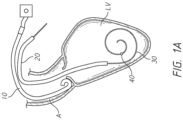
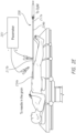
- Figures 1A-1F illustrate various methods of accessing a heart during a structural heart procedure.
- One of the pressure guidewire 30 or the pressure sensing device e.g., a pigtail catheter 10 or access catheter 20
- the other of the pressure guidewire 30 or the pressure sensing device may be used to calculate a downstream pressure curve (with respect to flow).
- a pigtail catheter 10 or access catheter 20 may be used to calculate an upstream pressure curve (with respect to flow) and the other of the pressure guidewire 30 or the pressure sensing device to calculate a downstream pressure curve (with respect to flow).
- Figure 1C illustrates a similar configuration to Figure 1A except the pressure sensor 40 is located proximal of the atraumatic curvature of the pressure guidewire 30.
- the sensing feature of the pigtail catheter 10 e.g., a distal end of a column of fluid in the catheter 10.
- the sensing features of the pigtail catheter 10 and the pressure guidewire 30 can be confirmed to be placed in the aorta A.
- pressure equalization may be performed in the aorta A.
- the pressure guidewire 30 may be advanced into the left ventricle LV to provide the upstream pressure curve while the pigtail catheter 10 remains in the aorta A to provide the downstream pressure curve.
- pigtail catheter 10 may be positioned in the aorta A to provide the downstream pressure curve.
- the pressure guidewire 30 extends through the pigtail catheter 10 in this embodiment to provide the upstream pressure curve.
- pressure equalization may be performed in the aorta A.
- the sensing feature of the pressure guidewire 30 can be advanced to the end of a fluid column in the pigtail catheter 10 or just distal thereto. The signals from the sensing feature of the pressure guidewire 30 and the fluid column can be compared to equalize them.
- the pressure guidewire 30 may be retrieve from the aortic pigtail and insert in the left ventricle via the access catheter like it is usually done while the pigtail catheter 10 remains in the aorta A to provide the downstream pressure curve.
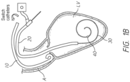
- the access catheter 20 or a separate delivery catheter exchanged with the access catheter 20 may be used to advance a valve dilation balloon, replacement valve, and or other device to the treatment site.
- the pressure guidewire 30 may extend through the access catheter 20 to the left ventricle LV.
- the access catheter 20 may provide pressure signals that can be used to generate an upstream pressure curve, while the pressure guidewire 30 provides pressure signals that can be used to generate a downstream pressure curve.
- any other delivery catheter exchanged with the access catheter may be used to provide the upstream pressure curve.
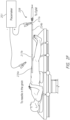
- the access catheter 20 may access the left ventricle LV through the apex P of a heart.
- a separate device (not shown) can be used to open a pathway through the apex P.
- the access catheter 20 can be advanced through such as device.
- the access catheter 20 or a separate delivery catheter exchanged with the access catheter 20 may be used to advance a valve dilation balloon, replacement valve, and or other device to the treatment site.
- the pressure guidewire 30 may extend through the access catheter 20 to the aorta A in an aortic valve procedure.
- the access catheter 20 may provide the pressure signals that can be used to calculate an upstream pressure curve, while the pressure guidewire 30 can provide signals that can be used to calculate a downstream pressure curve.
- any other delivery catheter exchanged with the access catheter may be used to provide the upstream pressure curve.
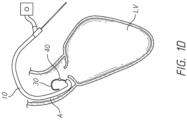
- FIG. 1F shows an aortic valve assessment or procedure via the apex P of the heart
- the pressure guidewire 30 can be advanced through the mitral valve M such that the sensing feature thereof is in the left atrium.
- the pressure guidewire can provide pressure signals that can be used to calculate a left atrial pressure curve (proximal or upstream pressure curve from the perspective of flow).
- the access catheter 20 can generate pressure signals that can be used to calculate a left ventricle pressure curve (distal or downstream pressure curve from the perspective of flow).
- valve dilation procedures sometimes called a valvuloplasty, or a valve implantation procedure
- natural circulation through the heart valve may be blocked by the valvuloplasty balloon, valve replacement delivery system, or other treatment device.
- pressure from the left ventricle LV or compression of the heart muscle may drive the treatment device back into the aorta A making it difficult to properly position the treatment device.
- Rapid pacing or defibrillating the left ventricle LV can reduce the pressure gradient between the aorta A and the left ventricle LV and also heart muscle forces and allow the clinician to complete the procedure.
- Conventional rapid pacing may involve introducing a temporary pace maker to the heart, but this usually requires a separate access point, for example a venous access point.
- the pressure guidewire 30 may be used to perform the rapid pacing.
- the pressure guidewire 30 may be introduced through the same access point as the access catheter 20 or other delivery catheter, which reduces the total number of access points.
- a current may be delivered to a proximal segment pressure guidewire and transmitted to a distal segment of the pressure guidewire via connector tube and/or the core wire, as explained in further detail below.
- the access catheter 20 or other delivery catheter may insulate at least an intermediate segment of the rapid pacing pressure guidewire 30 from the patient to prevent burns.
- the pressure guidewire 30 may include an insulator portion to isolate the pressure guidewire 30.
- the distal segment of the pressure guidewire may include a curvature allowing the current to contact ventricle walls in multiple locations.
- Figure 2A illustrates a diagnostic system 200 that can be used in the vasculature of a patient.
- the diagnostic system 200 is configured to determine whether the extent of valve damage is great enough to indicate that a balloon dilation (e.g., valvuloplasty), valve replacement or other catheter intervention ought to be performed.
- a balloon dilation e.g., valvuloplasty
- the diagnostic system 200 can include a monitor assembly 204 that is configured to be coupled to the pressure guidewire 208.
- the diagnostic system 200 may include a connection (indicated by the dashed line) that facilitates connection to and disconnection of the pressure guidewire 208 from the monitor assembly 204.
- the connection to and disconnection from the monitor assembly 204 is useful in allowing a clinician to use the pressure guidewire 208 initially for assessing the effect of the heart valve damage.
- the pressure guidewire 208 may also be used for delivering a treatment device such as a balloon catheter or valve delivery system.
- a fiber optic interface cable 202 can be used to couple the pressure guidewire 208 with the monitor assembly 204 by way of a handle 207.
- the system 200 receives an input from a tubular catheter body used to access the vasculature.
- the access catheter 20 may be an access catheter.
- a distal tip of the pressure sensing of or in the access catheter 20 can be positioned adjacent the treatment site such that pressure signals corresponding to the pressure on a first side of the treatment site, e.g., in the aorta, can be obtained. This pressure measurement is sometimes referred to herein as Pa.
- the system 200 may include a pressure sensing device, such as a pigtail catheter, delivered separate from the pressure guidewire to obtain Pa.
- the pressure guidewire 208 can take any suitable form.
- the pressure guidewire 208 may include a proximal segment that has a proximal end that is positioned outside the patient and a distal end that may be advanced through the access catheter 20 to the vasculature.
- the pressure guidewire 208 can be configured to have the flexibility to navigate the tortuous vasculature while maintaining structural integrity for pushability and torqueability.
- at least proximal section of the pressure guidewire 208 may be supported by a connector tube and/or core for structural integrity, while a distal section of the pressure guidewire 208 can be formed to include an atraumatic curvature 250, such as the coiled end shown in Figure 2B , to provide more flexibility and prevent puncture.
- a curved distal section may be joined to the pressure guidewire 208 to provide the atraumatic curvature 250.
- an optical sensor can be configured to sense pressure when exposed to blood.
- the optical sensor can be disposed within an interior space of the pressure guidewire 208 in fluid communication with an exterior of the pressure guidewire 208.
- the sensor may be an optical or electrical pressure sensor.
- the sensor can be selectively placed in communication with the monitor assembly 204 by pressure wire lead(s) disposed between the sensor and a proximal end of the pressure guidewire 208.
- the pressure wire lead(s) may be an optical fiber or an electrical wire.
- the pressure sensor may be located anywhere along the distal section of the pressure guidewire 208.
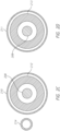
- the pressure sensor may be positioned near the distal-most tip of the guidewire at location 206D, along the curvature 250 of the guidewire at location 206C, at the transition to the curvature 250 of the guidewire at location 206B, or proximal of the curvature 250 of the guidewire at location 206A.
- location 206C may be at about 270 degrees around the curvature 250 from the straight region (around location 206A) of the pressure guidewire and location 206D may be about 540 degrees around the curvature from the straight region of the pressure guidewire.
- the pressure sensor may be located any position in the curved distal region of the pressure guidewire, for example between and including about 0 degrees to about 90 degrees, between and including about 90 degrees to about 180 degrees, between and including about 180 degrees to about 270 degrees, between and including about 270 degrees to about 360 degrees, between and including about 360 degrees to about 450 degrees, or between and including about 450 degrees to about 540 degrees from the straight region of the pressure guidewire.
- the pressure guidewire may include at least a first insulator section 234a and a second insulator section 234b spaced apart from the first insulator section 234a.
- the first insulator section 234a may be positioned at a distal portion of the pressure guidewire or closer to the distal end of the pressure guidewire compared to the proximal end of the pressure guidewire.
- the second insulator section 234b may extend between the first insulator section 234a and the proximal end of the pressure guidewire.
- the multiple, exposed conductive sections 217a, 217b provide a physician with the option of connecting the pacemaker 201 closer to the proximal end of the pressure guidewire 208 ( Figure 2F ) or closer to a distal end of the pressure guidewire ( Figure 2E ).
- One of the exposed conductive sections may be more conveniently located compared to the other exposed conductive sections.
- a clinician may desire to connect the pacemaker to an exposed conductive section closer to the distal end of the pressure guidewire when the pacemaker connection needs to be placed near the groin.
- a clinician may prefer to connect the pacemaker to an exposed conductive section closer to the proximal end of the pressure guidewire to avoid possible interference with the delivery system.
- FIGS 3 and 4 illustrate different pressure guidewires 308, 408 that may be used in any of the above-described methods. Numerals used to identify features of the pressure guidewire 308 are incremented by a factor of one hundred (100) to identify like features of the pressure guidewire 408. This numbering convention generally applies to the remainder of the figures. Any component of the pressure guidewires described herein can be interchanged.
- the pressure guidewires 308, 408 include an outer tube 310, 410 defining a lumen, a core wire 316, 416 extending at least partially through the lumen of the outer tube 310, 410, a pressure sensor assembly 318, 418 disposed within the lumen of the outer tube 310, 410, and/or a distal tip 432.
- the pressure guidewire 308 also can include a distal tip that can be the same as or similar to the tip 432 or any of the other tips disclosed herein.
- An outer diameter of the pressure guidewire 308, 408 may be uniform or substantially uniform along substantially the entire or entire working length of the pressure guidewire 308, 408.
- the outer diameter of the pressure guidewire 308 may be uniform or substantially uniform along the entire working length, excluding distal tip 432 or atraumatic curvature 250.
- the pressure guidewire 308, 408 may include an outer diameter of up to 0.035 inches, for example between 0.018 inches and 0.035 inches.
- the distal portion of the pressure guidewire 308, 408 may be form an atraumatic curvature 250 such as the coiled portion shown in Figure 2B .
- the distal portion of the pressure guidewire 308, 408 may remain straight from at least the pressure sensor of the pressure sensor assembly to the distal tip of the pressure guidewire.
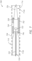
- FIG. 3 is a schematic view of one variation of the pressure sensing guidewire 308.
- the coil portion 312 may be a flat ribbon coil or a round coil.
- the coil portion 312 may extend along a majority of the working length of the pressure guidewire 308, along substantially the entire working length of the pressure guidewire 308, or along the entire working length of the pressure guidewire 308.
- the coil portion 312 provides sufficient flexibility and softness to avoid any trauma during use (e.g. perforation and/or dissection).
- the coil portion 312 also promotes safety in case of distal tip failure. When rapid pacing, the coil portion 312 may also ensure electrical contact with the heart.
- At least a proximal portion 328 of the core wire 316 may be concentric with the outer tube 310 and extend through at least a portion of the lumen of the outer tube 310.
- the core wire 316 may extend along a majority of the working length of the pressure guidewire 308, along substantially the entire working length of the pressure guidewire 308, or along the entire working length of the pressure guidewire 308.
- the core wire 316 provides the pressure guidewire 308 with sufficient rigidity for pushability and to prevent kinking. It also provides sufficient rigidity to support the delivery catheter during valve implementation.
- At least a portion of the core wire 316 may include a reduced diameter portion 326 to provide space in the lumen outer tube 310 for a pressure sensor 322.
- the reduced diameter portion 326 may be tapered toward the distal end of the pressure guidewire 308.
- the transition between the proximal portion 328 and the reduced diameter portion 326 of the core wire 316 may be positioned proximal of at least a portion or the entirety of the atraumatic curvature 250 in the distal section of the pressure guidewire 308 (shown in Figure 2B ) to promote a flexible transition to the atraumatic curvature 250 of the pressure guidewire 308.
- the core wire 316 would continue to extend through at least a portion of the atraumatic curvature 250.
- This flexible transition acts as a force absorber and ensures no kink is formed in the proximal section of the atraumatic curvature 250 of the pressure guidewire 308.
- a kink could complicate a procedure, such as advancing another catheter over the guidewire 308 or removing the guidewire 308 from the patient without trauma.
- the proximal portion 328 of the core wire 316 may include an outer diameter of up to 0.03 inches, for example between 0.015 inches and 0.03 inches.
- a reduced diameter portion 326 of the core wire 316 may include an outer diameter that is less than one-third, or less than one-fourth, of the outer diameter of the proximal portion 328 of the core wire 316.
- the reduced diameter portion 326 of the core wire 316 may include an outer diameter of less than 0.01 inches or less than 0.0075 inches.
- the core wire 316 may include a conductive material such as stainless steel to provide a conductive path for current applied to the guidewire 308 in connection with a rapid pacing technique as described above.
- a proximal end of the core wire 316 may be exposed from the proximal end of the outer tube 310 for connection to the monitor display 204 and/or connection to a current generator. Less than ten percent, or less than five percent, of a length of the core wire 316 may be exposed from the proximal end of the outer tube 310 for connection to a current source for rapid pacing.
- the distal tip 432 is a separate component adhered, welded, and/or otherwise joined to the coil portion 412 and/or the core wire 416.
- the distal tip may be joined to an inner surface of the coil portion 412 and/or the distal most edge of the coil portion 412.
- the core wire 416 may be bent up to 180 degrees within the outer tube 410 to strengthen the adhesive joint to the distal tip 432.
- the distal tip 432 may be an enlarged distal end of the core wire 416 that is distal of the reduced diameter portion 426.
- the distal end of the core wire 416 may be adhered, welded, and/or otherwise joined to the inner surface and/or distal most edge of the coil portion 412.
- Figures 5 to 10C illustrate further variations of pressure guidewires that may be used in any of the above-described methods.
- the pressure guidewires described below may include any of the features of the above-described pressure guidewires 308, 408.
- the pressure guidewires shown in Figures 5 to 10C include an outer tube defining a lumen, connector tube positioned radially inward of the outer tube, a pressure sensor assembly disposed within the lumen of the outer tube, and/or a distal tip.
- An outer diameter of the pressure guidewire may be uniform or substantially uniform along substantially the entire or entire working length of the pressure guidewire.
- the outer diameter of the pressure guidewire may be uniform or substantially uniform along the entire working length, excluding distal tip or grinded down curvature.
- the pressure guidewire may include an outer diameter of up to 0.035 inches, for example between 0.018 inches and 0.035 inches.
- the distal portion of the pressure guidewire may be formed to an atraumatic curvature 250 as shown in Figure 2B . In other configurations, the distal portion of the pressure guidewire may remain straight.
- the connector tube may include an inner diameter that is less than one-third, or less than one-fourth an outer diameter of the connector tube.
- the connector tube may include an outer diameter of up to 0.035 inches, for example between 0.018 inches and 0.035 inches, and an inner diameter of less than 0.01 inches, for example less than 0.007 inches.
- the connector tube may have a uniform outer diameter (see Figure 5 ) or a non-uniform diameter (see Figure 6 ). In the non-uniform configurations, a reduced diameter portion of the connector tube may have an outer diameter of less than or equal to about 0.027 inches.
- the connector tube may extend along a majority of or substantially the entire working length of the pressure guidewire. For example, the connector tube may extend at least eighty percent, or at least ninety percent, of the working length of the pressure guidewire.
- the connector tube may be constructed of a conductive metal.
- the connector tube may be a stainless steel tube.
- a proximal end of the connector tube may be exposed from the proximal end of the outer tube for connection to the monitor display and/or connection to a current generator. Thus, at least the proximal end of the connector tube may be uncoated.
- FIG. 5 is a schematic view another variation of the pressure sensing guidewire 508.
- the coiled portion may be a flat ribbon coil or a round coil.
- the coiled portion may include two coiled sections 512a, 512b separated from each other by a sensor housing 542. Together, the coil portions 512a, 512b may extend along a majority of the working length of the pressure guidewire 508 or along substantially the entire working length of the pressure guidewire 508. For example, together, the coiled portions 512a, 512b may extend at least eighty percent, or at least ninety percent, of the working length of the pressure guidewire 508.
- At least a portion of the pressure guidewire 508 may be covered by a lubricious insulator, for example a polymeric layer such as PTFE.
- a lubricious insulator for example a polymeric layer such as PTFE.
- the insulator may also electrically isolate portions of the pressure guidewire 508.
- the insulator may replace the need for a separate catheter body to electrically isolate the pressure guidewire 508.
- FIG. 6 is a cross-sectional view of another variation of the pressure sensing guidewire 608.
- the pressure sensing guidewire 608 is similar to the pressure sensing guidewire 508 except as described differently below.
- the disclosure in connection with Figure 6 can be seen to supplement that of Figure 5 .
- the pressure sensing guidewire 608 includes a distal tip 632.
- the distal tip 632 is similar to the distal tip 432 except as described differently below.
- the distal tip 632 provide for atraumatic interaction with blood vessels, valves and heart wall chambers.
- the tip 632 also may reduce or prevent ingress of foreign matter, e.g., components or fluid, through a distal end of the pressure guidewire 608.
- the distal tip 632 may have a hemispherical shape.
- the distal tip 632 is a separate component adhered, welded, and/or otherwise joined to the coil portion 612a and/or the core wire 616.
- the distal tip 632 may be joined to an inner surface of the coil portion 612a and/or the distal most edge of the coil portion 612a.
- the core wire 616 may be bent up to 180 degrees within the outer tube 610 to strengthen the adhesive joint to the distal tip 632.
- the distal tip 632 may be an enlarged distal end of the core wire 616 that is distal of the reduced diameter portion 626.
- the distal end of the core wire 616 may be adhered, welded, and/or otherwise joined to an inner surface and/or distal most edge of the coil portion 612a.
- the atraumatic portion of the distal tip 632 may be formed from the core wire 616, such as by melting or otherwise reforming an enlarged segment of the core wire 616 to create the desired shape.
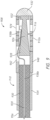
- Figure 7 is a schematic view of another variation of the pressure sensing guidewire 708.
- the pressure sensing guidewire 708 is similar to the pressure sensing guidewire 508 except that sensor housing 742 and pressure sensor 722 may be positioned more distally into the distal curvature 250 of the pressure guidewire 708, for example at locations 206B or 206C shown in Figure 2B .
- sensor housing 742 and the pressure sensor 722 may be positioned in a region in which the connector tube 730 and/or core wire 716 have transitioned to a reduced diameter.
- the connector tube 730 may have a reduced diameter section 746 at the distal end of the connector tube 730.
- the connector tube 730 may be tapered toward the reduced diameter section 746 at tapered portion 754.
- a diameter of the proximal end of the core wire 716 may also be less than an outermost diameter of the connector tube 730, e.g. at a distal end or distal region thereof.
- an outer diameter of the sensor housing 742 may also be reduced compared to the sensor housing 542.
- An outer diameter of a proximal portion of the connector tube 730 may be less than or equal to an inner diameter of the coil portion 712b and/or greater than an inner diameter of the sensor housing 742.
- the proximal portion of the connector tube 730 may be positioned within the coil portion 712b, while the reduced diameter section 746 may be positioned within the sensor housing 742.
- an inner diameter of coil portion 712a and/or coil portion 712b may be different from, e.g., larger than, an inner diameter of the sensor housing 742.
- An outer diameter of the coil portions 712a, 712b may be about the same as the outer diameter of the sensor housing 742.
- an inner diameter of the coil portion 712a and/or coil portion 712b may be the same as the inner diameter of the sensor housing 742 (similar to guidewire 608).
- FIG 8 is a schematic view of another variation of the pressure sensing guidewire 808.
- the pressure sensing guidewire 808 is similar to the pressure sensing guidewire 708 except that sensor housing 842 and pressure sensor 822 may be positioned more distally into the distal curvature 250 of the pressure guidewire 808, for example at location 206D shown in Figure 2B .
- the reduced diameter portion 826 of the core wire 816 may have a sufficiently reduced diameter to permit the positioning of the sensor 822 radially between the distal coil portion 812a and the reduced diameter portion 826 of the core wire 816.
- the sensor 822 may have a separate sensor housing 842 positioned around the sensor 822.
- the pressure guidewire 808 includes a connector 848 extending between the coil portions 812a, 812b.
- the connector 848 may include an opening 852 to permit at least one pressure wire lead 820 to transition from the first section 838a that is concentric with the outer tube 410 and within the connector tube 830 to the second section 838b that is off-axis relative to the longitudinal axis L of the outer tube 810.
- the opening 840 may be a partial thickness cut out or extend through the full thickness of the outer tube 810. If the opening 830 extends through the full thickness of the outer tube 810, the opening 840 may be sealed, for example with adhesive, to prevent fluid from flowing into the pressure guidewire through the opening 840.
- Figure 9 is a cross-sectional view of another variation of the pressure sensing guidewire 908.
- the pressure sensing guidewire 908 is similar to the pressure sensing guidewire 808 except that except that Figure 9 includes distal tip 932.
- the distal tip 932 may include any of the features of the distal tip 632 shown in Figure 6 .
- the outer tube 910 includes an insulator portion 934 and a coil portion 912 joined by the connector 948.
- the coil portion 912 may be a flat ribbon coil or a round coil.
- the insulator portion 934 surrounds at least a portion of the connector tube 930.
- the insulator portion 934 may include a polymeric layer such as PTFE to electrically isolate the connector tube 930 from the patient during rapid pacing.
- a proximal end 956 of the connector tube 930 may be exposed from the proximal end of the insulator portion 934 for connection to the monitor and/or connection to a current generator. Thus, at least the proximal end of the connector tube 930 may be uncoated.
- the connector 948 may be a metal tube joining the insulator portion 934 and the coil portion 912, but in other variations, the connector 948 may be a welded portion joining the insulator portion 934 and the coil portion 912.
- the one or more pressure wires leads 920 may be sealed to the inner lumen of the connector tube 930, for example using adhesive, to prevent fluid from flowing proximally and ensuring concentricity of the optical fiber for signal transmission.
- the pressure sensor 922 may be exposed to blood or other fluid through the spacing or gaps in the coil portion 912.
- the outer tube 910 may also include sensor housing section 924.
- the sensor housing section may be stiffer than the remainder of the coil portion 912.
- the sensor housing section 924 may be a metallic tube splitting the coil portion 912 into two sections.
- the sensor housing section 924 may be mounted to a distal portion of a first coil section of the coil portion 912 and to a proximal portion of a second coil section of the coil portion 912.
- the sensor housing section 924 may include one or more openings to expose the pressure sensor 922 to blood or other fluid.
- the coil portion 912 may include two coils welded together to create a stiffened section that serves as the sensor housing section 924.
- FIGS 10A-10C illustrate cross-sectional views of variations of the pressure sensing guidewire 1008.
- the pressure sensing guidewire 1008 is similar to the pressure sensing guidewire 608 or 708 except that an insulator portion 1034 may surround at least a portion of the conductive connector tube 1030 and/or the pressure wire lead(s) 1020.
- the connector tube 1030 may have a uniform diameter. However, in other configurations (see Figure 10C ), a distal portion of the connector tube 1030 may have a reduced diameter.
- the connector tube 1030 may be tapered toward the distal portion of the connector tube 1030.
- the insulator portion 1034 may form at least a portion of the outer tube 1010.
Landscapes
- Health & Medical Sciences (AREA)
- Life Sciences & Earth Sciences (AREA)
- Molecular Biology (AREA)
- Surgery (AREA)
- Biophysics (AREA)
- Pathology (AREA)
- Engineering & Computer Science (AREA)
- Biomedical Technology (AREA)
- Heart & Thoracic Surgery (AREA)
- Medical Informatics (AREA)
- Cardiology (AREA)
- Physics & Mathematics (AREA)
- Animal Behavior & Ethology (AREA)
- General Health & Medical Sciences (AREA)
- Public Health (AREA)
- Veterinary Medicine (AREA)
- Vascular Medicine (AREA)
- Physiology (AREA)
- Measuring Pulse, Heart Rate, Blood Pressure Or Blood Flow (AREA)
- Media Introduction/Drainage Providing Device (AREA)
- Electrotherapy Devices (AREA)
- Prostheses (AREA)
Applications Claiming Priority (4)
| Application Number | Priority Date | Filing Date | Title |
|---|---|---|---|
| US201962849768P | 2019-05-17 | 2019-05-17 | |
| US201962926737P | 2019-10-28 | 2019-10-28 | |
| PCT/US2020/032742 WO2020236492A1 (en) | 2019-05-17 | 2020-05-13 | Pressure sensing guidewires, systems and methods for structural heart procedures |
| EP20809315.3A EP3969096A4 (de) | 2019-05-17 | 2020-05-13 | Druckempfindliche führungsdrähte, systeme und verfahren für strukturelle herzprozeduren |
Related Parent Applications (1)
| Application Number | Title | Priority Date | Filing Date |
|---|---|---|---|
| EP20809315.3A Division EP3969096A4 (de) | 2019-05-17 | 2020-05-13 | Druckempfindliche führungsdrähte, systeme und verfahren für strukturelle herzprozeduren |
Publications (2)
| Publication Number | Publication Date |
|---|---|
| EP4574027A2 true EP4574027A2 (de) | 2025-06-25 |
| EP4574027A3 EP4574027A3 (de) | 2025-10-01 |
Family
ID=73458850
Family Applications (2)
| Application Number | Title | Priority Date | Filing Date |
|---|---|---|---|
| EP25172298.9A Pending EP4574027A3 (de) | 2019-05-17 | 2020-05-13 | Druckmessungsführungsdrähte, systeme und verfahren für strukturelle herzeingriffe |
| EP20809315.3A Ceased EP3969096A4 (de) | 2019-05-17 | 2020-05-13 | Druckempfindliche führungsdrähte, systeme und verfahren für strukturelle herzprozeduren |
Family Applications After (1)
| Application Number | Title | Priority Date | Filing Date |
|---|---|---|---|
| EP20809315.3A Ceased EP3969096A4 (de) | 2019-05-17 | 2020-05-13 | Druckempfindliche führungsdrähte, systeme und verfahren für strukturelle herzprozeduren |
Country Status (6)
| Country | Link |
|---|---|
| US (1) | US20220192520A1 (de) |
| EP (2) | EP4574027A3 (de) |
| JP (2) | JP7679310B2 (de) |
| CN (1) | CN114096301A (de) |
| CA (1) | CA3140414A1 (de) |
| WO (1) | WO2020236492A1 (de) |
Families Citing this family (7)
| Publication number | Priority date | Publication date | Assignee | Title |
|---|---|---|---|---|
| FR3118865B1 (fr) * | 2021-01-19 | 2023-02-10 | Electroducer | Ensemble de diagnostic coronaire avec guide-fil servant à la fois pour l’assistance de stimulation cardiaque et la mesure de la réserve coronaire. |
| WO2023014531A1 (en) | 2021-08-06 | 2023-02-09 | Solo Pace Inc. | Systems, methods, and apparatus for external cardiac pacing |
| US11872403B2 (en) | 2021-08-06 | 2024-01-16 | Solo Pace Inc. | Systems, methods, and apparatus for external cardiac pacing |
| JP2023115638A (ja) * | 2022-02-08 | 2023-08-21 | 朝日インテック株式会社 | ガイドワイヤ |
| EP4661743A1 (de) * | 2023-02-01 | 2025-12-17 | Stallion Cardio, LLC | System und verfahren zur messung der eigenschaften des koronararteriensystems |
| US12357833B2 (en) | 2023-08-01 | 2025-07-15 | Merit Medical Systems, Inc. | Systems, methods, and apparatus for ambulatory cardiac pacing |
| CN119818239B (zh) * | 2025-03-05 | 2026-02-17 | 西安交通大学 | 一种用于人工瓣膜的输送系统 |
Family Cites Families (24)
| Publication number | Priority date | Publication date | Assignee | Title |
|---|---|---|---|---|
| EP0738495B1 (de) * | 1995-04-18 | 2002-06-26 | Schneider (Europe) GmbH | Druckmessführungsdraht |
| US5938624A (en) * | 1997-09-10 | 1999-08-17 | Radi Medical Systems Ab | Male connector with a continous surface for a guide wire and method therefor |
| US6106486A (en) * | 1997-12-22 | 2000-08-22 | Radi Medical Systems Ab | Guide wire |
| JP4222775B2 (ja) | 2001-06-15 | 2009-02-12 | ラディ・メディカル・システムズ・アクチェボラーグ | 生物の体内に挿入可能な測定装置 |
| US8579825B2 (en) | 2001-06-15 | 2013-11-12 | Radi Medical Systems Ab | Electrically conductive guide wire |
| DE602007006859D1 (de) * | 2006-04-28 | 2010-07-15 | Radi Medical Systems | Sensor und Führungsdrahtanordnung |
| US20080077050A1 (en) * | 2006-09-08 | 2008-03-27 | Radi Medical Systems Ab | Electrical connector for medical device |
| US8174395B2 (en) | 2006-11-20 | 2012-05-08 | St. Jude Medical Systems Ab | Transceiver unit in a measurement system |
| WO2013169492A1 (en) | 2012-05-08 | 2013-11-14 | Angiometrix Corporation | Guidewire assembly methods and apparatus |
| US9655531B2 (en) * | 2012-06-28 | 2017-05-23 | Volcano Corporation | Connection structures for intravascular devices and associated systems and methods |
| JP6041427B2 (ja) | 2012-08-31 | 2016-12-07 | 朝日インテック株式会社 | センサ付きガイドワイヤ |
| US9924903B2 (en) | 2012-12-27 | 2018-03-27 | Volcano Corporation | Pressure-sensing guide wire with sliding pressure sensor |
| US20140187980A1 (en) | 2012-12-28 | 2014-07-03 | Volcano Corporation | Hypotube Sensor Mount for Sensored Guidewire |
| EP2938253B1 (de) | 2012-12-31 | 2021-03-24 | Philips Image Guided Therapy Corporation | Führungsdraht mit wandinterne hyporohrsensorhalterung und das zugehörige herstellungsverfahren |
| WO2014138513A1 (en) * | 2013-03-08 | 2014-09-12 | The Cleveland Clinic Foundation | Exchange guidewire |
| JP6395826B2 (ja) | 2013-10-25 | 2018-09-26 | セント ジュード メディカル コーディネイション センター ベーファウベーアー | センサ・ガイド・ワイヤ装置及びセンサ・ガイド・ワイヤ装置を備えたシステム |
| WO2015077328A1 (en) | 2013-11-22 | 2015-05-28 | Volcano Corporation | Sensor mounting assembly for sensored guidewire and associated devices, systems, and methods |
| CN107072559A (zh) * | 2014-08-28 | 2017-08-18 | 皇家飞利浦有限公司 | 具有填充有粘合剂的柔性元件的血管内设备、系统和方法 |
| WO2016038488A1 (en) | 2014-09-11 | 2016-03-17 | Koninklijke Philips N.V. | Intravascular devices, systems, and methods having a sensing element embedded in adhesive |
| EP3324837B1 (de) | 2015-07-17 | 2020-04-01 | Koninklijke Philips N.V. | Intravaskuläre vorrichtungen, systeme und verfahren mit einem angeklebten formband |
| JP6929854B2 (ja) * | 2015-12-28 | 2021-09-01 | ボストン サイエンティフィック サイムド,インコーポレイテッドBoston Scientific Scimed,Inc. | 抗血栓コーティングを有する医療装置 |
| US11090006B2 (en) * | 2016-02-03 | 2021-08-17 | Cormetrics Llc | Modular sensing guidewire |
| EP3437552A4 (de) | 2016-03-29 | 2020-03-11 | Nipro Corporation | Sensorsteuerschaltung und blutmessungsvorrichtung |
| CA3021877C (en) * | 2017-11-14 | 2019-04-09 | Three Rivers Cardiovascular Systems Inc. | Dual sensor system for continuous blood pressure monitoring during transcatheter heart valve therapies |
-
2020
- 2020-05-13 EP EP25172298.9A patent/EP4574027A3/de active Pending
- 2020-05-13 US US17/595,425 patent/US20220192520A1/en active Pending
- 2020-05-13 JP JP2021568591A patent/JP7679310B2/ja active Active
- 2020-05-13 CA CA3140414A patent/CA3140414A1/en active Pending
- 2020-05-13 CN CN202080050480.6A patent/CN114096301A/zh active Pending
- 2020-05-13 WO PCT/US2020/032742 patent/WO2020236492A1/en not_active Ceased
- 2020-05-13 EP EP20809315.3A patent/EP3969096A4/de not_active Ceased
-
2025
- 2025-03-24 JP JP2025048499A patent/JP2025089439A/ja active Pending
Also Published As
| Publication number | Publication date |
|---|---|
| JP7679310B2 (ja) | 2025-05-19 |
| US20220192520A1 (en) | 2022-06-23 |
| JP2022532668A (ja) | 2022-07-15 |
| EP3969096A4 (de) | 2023-01-11 |
| CA3140414A1 (en) | 2020-11-26 |
| WO2020236492A1 (en) | 2020-11-26 |
| EP4574027A3 (de) | 2025-10-01 |
| JP2025089439A (ja) | 2025-06-12 |
| CN114096301A (zh) | 2022-02-25 |
| EP3969096A1 (de) | 2022-03-23 |
Similar Documents
| Publication | Publication Date | Title |
|---|---|---|
| EP4574027A2 (de) | Druckmessungsführungsdrähte, systeme und verfahren für strukturelle herzeingriffe | |
| JP7288940B2 (ja) | ペーシングガイドワイヤ | |
| US12507900B2 (en) | Pressure based structural heart assessment systems and methods | |
| US11406271B2 (en) | Dual sensor system for continuous blood pressure monitoring during transcatheter heart valve therapies | |
| EP2473224B1 (de) | Koaxialer transseptaler führungsdraht und nadelanordnung dafür | |
| US10722175B2 (en) | System and apparatus comprising a multisensor guidewire for use in interventional cardiology | |
| CN103282074B (zh) | 可操纵腔内设备和方法 | |
| US20110022057A1 (en) | Apparatus and methods for transferring an implanted elongate body to a remote site | |
| CN108025160A (zh) | 具有灌注开口的引导延伸导管 | |
| US20200305733A1 (en) | System and apparatus comprising a multisensor guidewire for use in interventional cardiology | |
| EP3389507B1 (de) | Einführersysteme und vorrichtungen zur herzklappenreduktion | |
| US20260108351A1 (en) | Apparatuses for antegrade transcatheter valve repair or implantation | |
| EP4033970B1 (de) | Systeme zur intraoperativen herzdrucküberwachung | |
| JP2022526838A (ja) | 展開システムアクセスシース | |
| CN115645027A (zh) | 远端可调的导管、消融装置及消融系统 | |
| TW202519283A (zh) | 回聲導線 | |
| HK1236000A1 (en) | System and apparatus comprising a multisensor guidewire for use in interventional cardiology |
Legal Events
| Date | Code | Title | Description |
|---|---|---|---|
| PUAI | Public reference made under article 153(3) epc to a published international application that has entered the european phase |
Free format text: ORIGINAL CODE: 0009012 |
|
| STAA | Information on the status of an ep patent application or granted ep patent |
Free format text: STATUS: THE APPLICATION HAS BEEN PUBLISHED |
|
| AC | Divisional application: reference to earlier application |
Ref document number: 3969096 Country of ref document: EP Kind code of ref document: P |
|
| AK | Designated contracting states |
Kind code of ref document: A2 Designated state(s): AL AT BE BG CH CY CZ DE DK EE ES FI FR GB GR HR HU IE IS IT LI LT LU LV MC MK MT NL NO PL PT RO RS SE SI SK SM TR |
|
| REG | Reference to a national code |
Ref country code: DE Ref legal event code: R079 Free format text: PREVIOUS MAIN CLASS: A61B0005021500 Ipc: A61M0025090000 |
|
| PUAL | Search report despatched |
Free format text: ORIGINAL CODE: 0009013 |
|
| AK | Designated contracting states |
Kind code of ref document: A3 Designated state(s): AL AT BE BG CH CY CZ DE DK EE ES FI FR GB GR HR HU IE IS IT LI LT LU LV MC MK MT NL NO PL PT RO RS SE SI SK SM TR |
|
| RIC1 | Information provided on ipc code assigned before grant |
Ipc: A61M 25/09 20060101AFI20250826BHEP Ipc: A61B 5/0215 20060101ALI20250826BHEP Ipc: A61B 5/00 20060101ALI20250826BHEP |
|
| STAA | Information on the status of an ep patent application or granted ep patent |
Free format text: STATUS: REQUEST FOR EXAMINATION WAS MADE |