EP4574060A2 - Drahtlose arrays für chirurgische klammergeräte - Google Patents
Drahtlose arrays für chirurgische klammergeräte Download PDFInfo
- Publication number
- EP4574060A2 EP4574060A2 EP24222602.5A EP24222602A EP4574060A2 EP 4574060 A2 EP4574060 A2 EP 4574060A2 EP 24222602 A EP24222602 A EP 24222602A EP 4574060 A2 EP4574060 A2 EP 4574060A2
- Authority
- EP
- European Patent Office
- Prior art keywords
- anvil
- handle
- transceiver
- assembly
- stapling head
- Prior art date
- Legal status (The legal status is an assumption and is not a legal conclusion. Google has not performed a legal analysis and makes no representation as to the accuracy of the status listed.)
- Pending
Links
Images






Classifications
-
- A—HUMAN NECESSITIES
- A61—MEDICAL OR VETERINARY SCIENCE; HYGIENE
- A61B—DIAGNOSIS; SURGERY; IDENTIFICATION
- A61B17/00—Surgical instruments, devices or methods
- A61B17/11—Surgical instruments, devices or methods for performing anastomosis; Buttons for anastomosis
- A61B17/115—Staplers for performing anastomosis, e.g. in a single operation
- A61B17/1155—Circular staplers comprising a plurality of staples
-
- A—HUMAN NECESSITIES
- A61—MEDICAL OR VETERINARY SCIENCE; HYGIENE
- A61B—DIAGNOSIS; SURGERY; IDENTIFICATION
- A61B17/00—Surgical instruments, devices or methods
- A61B2017/00017—Electrical control of surgical instruments
-
- A—HUMAN NECESSITIES
- A61—MEDICAL OR VETERINARY SCIENCE; HYGIENE
- A61B—DIAGNOSIS; SURGERY; IDENTIFICATION
- A61B17/00—Surgical instruments, devices or methods
- A61B2017/00017—Electrical control of surgical instruments
- A61B2017/00022—Sensing or detecting at the treatment site
-
- A—HUMAN NECESSITIES
- A61—MEDICAL OR VETERINARY SCIENCE; HYGIENE
- A61B—DIAGNOSIS; SURGERY; IDENTIFICATION
- A61B17/00—Surgical instruments, devices or methods
- A61B2017/00017—Electrical control of surgical instruments
- A61B2017/00022—Sensing or detecting at the treatment site
- A61B2017/00026—Conductivity or impedance, e.g. of tissue
-
- A—HUMAN NECESSITIES
- A61—MEDICAL OR VETERINARY SCIENCE; HYGIENE
- A61B—DIAGNOSIS; SURGERY; IDENTIFICATION
- A61B17/00—Surgical instruments, devices or methods
- A61B2017/00017—Electrical control of surgical instruments
- A61B2017/00221—Electrical control of surgical instruments with wireless transmission of data, e.g. by infrared radiation or radiowaves
-
- A—HUMAN NECESSITIES
- A61—MEDICAL OR VETERINARY SCIENCE; HYGIENE
- A61B—DIAGNOSIS; SURGERY; IDENTIFICATION
- A61B17/00—Surgical instruments, devices or methods
- A61B2017/00367—Details of actuation of instruments, e.g. relations between pushing buttons, or the like, and activation of the tool, working tip, or the like
-
- A—HUMAN NECESSITIES
- A61—MEDICAL OR VETERINARY SCIENCE; HYGIENE
- A61B—DIAGNOSIS; SURGERY; IDENTIFICATION
- A61B17/00—Surgical instruments, devices or methods
- A61B2017/00367—Details of actuation of instruments, e.g. relations between pushing buttons, or the like, and activation of the tool, working tip, or the like
- A61B2017/00398—Details of actuation of instruments, e.g. relations between pushing buttons, or the like, and activation of the tool, working tip, or the like using powered actuators, e.g. stepper motors, solenoids
-
- A—HUMAN NECESSITIES
- A61—MEDICAL OR VETERINARY SCIENCE; HYGIENE
- A61B—DIAGNOSIS; SURGERY; IDENTIFICATION
- A61B17/00—Surgical instruments, devices or methods
- A61B2017/00681—Aspects not otherwise provided for
- A61B2017/00734—Aspects not otherwise provided for battery operated
-
- A—HUMAN NECESSITIES
- A61—MEDICAL OR VETERINARY SCIENCE; HYGIENE
- A61B—DIAGNOSIS; SURGERY; IDENTIFICATION
- A61B17/00—Surgical instruments, devices or methods
- A61B2017/00982—General structural features
-
- A—HUMAN NECESSITIES
- A61—MEDICAL OR VETERINARY SCIENCE; HYGIENE
- A61B—DIAGNOSIS; SURGERY; IDENTIFICATION
- A61B17/00—Surgical instruments, devices or methods
- A61B17/11—Surgical instruments, devices or methods for performing anastomosis; Buttons for anastomosis
- A61B2017/1132—End-to-end connections
Definitions
- the present disclosure generally describes surgical instruments with a plurality of transceivers that can communicate information from the end of the surgical instrument and, more particularly, to surgical staplers with an anvil transceiver and a handle transceiver that receives signals from the anvil transceiver.
- portions of a patient's digestive tract may be cut and removed to eliminate undesirable tissue or for other reasons.
- portions of the digestive tract may be coupled together in an end-to-end anastomosis.
- the end-to-end anastomosis may provide a substantially unobstructed flow path from one portion of the digestive tract to the other portion of the digestive tract, without also providing any kind of leaking at the site of the anastomosis.
- an instrument that may be used to provide an end-to-end anastomosis is a circular stapler.
- Some such staplers are operable to clamp down on layers of tissue, cut through the clamped layers of tissue, and drive staples through the clamped layers of tissue to substantially seal the layers of tissue together near the severed ends of the tissue layers, thereby joining the two severed ends of the anatomical lumen together.
- the circular stapler may be configured to sever the tissue and seal the tissue substantially simultaneously.
- the circular stapler may sever excess tissue that is interior to an annular array of staples at an anastomosis, to provide a substantially smooth transition between the anatomical lumen sections that are joined at the anastomosis.
- Circular staplers may be used in open procedures or in endoscopic procedures. In some instances, a portion of the circular stapler is inserted through a patient's naturally occurring orifice.
- the distal end of the circular stapler is, therefore, positioned within the patient.
- the distal end can include a stapling head assembly that can generate different types of digital information.
- One issue inherent with circular staplers, therefore, is that the distal end is separable from the proximal, handle end and as such it is difficult to send this digital information from the stapling head assembly to an external device, such as a computer in the operating room.
- the apparatus can include a stapling head assembly.
- the apparatus can include an anvil detachably attachable to the stapling head assembly.
- the apparatus can include a handle assembly.
- the handle assembly can include a handle controller, a connector, and a handle transceiver configured to wirelessly transmit a first signal to an external hub.
- the handle transceiver can be separated from the handle controller and can be in electrical communication with the handle controller via the connector.
- the handle assembly can include a knob rotatable to adjust a gap distance between anvil surface and the handle assembly.
- the handle transceiver can be positioned within the knob.
- the handle assembly can include a pistol grip.
- the handle transceiver can be positioned within the pistol grip.
- the handle transceiver can be encased within a shroud to shield the handle transceiver from signal noise from a motor.
- the handle assembly can include a battery housing including a battery and a housing cavity sized to accept the battery housing.
- the battery housing can be insertable and removable from the housing cavity.
- the handle transceiver can be positioned on the battery housing.
- the handle assembly can include a first connector positioned on the battery housing and in electrical communication with the handle transceiver and a second connector positioned within the housing cavity and in electrical communication with the handle controller.
- the first connector and the second can be configured to contact one another when the battery housing can be positioned within the housing cavity.
- the handle assembly can include a battery housing including a battery and a housing cavity sized to accept the battery housing.
- the battery housing can be insertable and removable from the housing cavity.
- the handle transceiver can be positioned within the housing cavity.
- the handle assembly can include a display positioned on a display panel visible from an exterior of the handle assembly.
- the handle transceiver can be positioned on the display panel.
- the anvil can be removably attached to the stapling head assembly and can include one or more sensors configured to output signals to the handle controller.
- the anvil can include an anvil transceiver.
- the one or more sensors can be configured to generate a second signal comprising first sensor data.
- the one or more sensors can be configured to transmit the first signal to the anvil transceiver.
- the handle transceiver can be configured to communicate wirelessly with the anvil transceiver and can be operable as a wireless relay between the anvil transceiver and the external hub.
- the apparatus can include a stapling head assembly.
- the stapling head assembly can include a deck surface, an array of staple openings formed through the deck surface, and a plurality of staples associated with the array of staple openings.
- the stapling head assembly can be operable to drive the staples through the array of staple openings.
- the apparatus can include an anvil detachably attachable to the stapling head assembly.
- the anvil can include an anvil surface configured to compress tissue against the deck surface.
- the anvil surface can define an array of staple forming pockets.
- the anvil can include an anvil power source.
- the anvil can include an anvil transceiver.
- the apparatus can include a handle assembly.
- the handle assembly can include a handle controller and a handle transceiver configured to communicate wirelessly with both the anvil transceiver and an external hub.
- the handle transceiver can be operable as a wireless relay to receive a first signal from the anvil transceiver and transmit a second signal to the external hub.
- the anvil further can include a position sensor operable to detect an orientation of the anvil within a patient.
- the first signal can include information related to the orientation of the anvil.
- the anvil further can include a surface sensor positioned on the anvil surface.
- the surface sensor can be operable to detect contact of tissue upon the anvil surface.
- the first signal can include information related to the contact.
- the surface sensor can be one of a plurality of surface sensors.
- the plurality of surface sensors can be configured to detect compression of tissue between the anvil surface and the deck surface.
- the anvil further can include a plurality of staple pocket sensors, each staple pocket sensor positioned within one of the staple forming pockets and configured to detect contact by a staple .
- the first signal can include information from one or more of the plurality of staple pocket sensors.
- the handle assembly can include a knob rotatable to adjust a gap distance between anvil surface and the deck surface.
- the handle transceiver can be positioned within the knob.
- the handle assembly can include a pistol grip.
- the handle transceiver can be positioned within the pistol grip.
- the handle transceiver can be encased within a shroud to shield the handle transceiver from signal noise from a motor.
- the handle assembly can include a battery housing including a battery.
- the handle assembly can include a housing cavity sized to accept the battery housing.
- the battery housing can be insertable and removable from the housing cavity.
- the handle transceiver can be positioned on the battery housing.
- the handle assembly can include: a first connector positioned on the battery housing an in electrical communication with the handle transceiver, and can include a second connector positioned within the housing cavity and in electrical communication with the handle controller.
- the first connector and the second connector can be configured to contact one another when the battery housing can be positioned within the housing cavity.
- the handle assembly can include a battery housing including a battery, and a housing cavity sized to accept the battery housing.
- the battery housing can be insertable and removable from the housing cavity.
- the handle transceiver can be positioned within the housing cavity.
- the handle assembly can include a display positioned on a display panel visible from an exterior of the handle assembly.
- the handle transceiver can be positioned on the display panel.
- the first signal and the second signal can be transmitted at different frequencies.
- the apparatus can include a stapling head assembly.
- the apparatus can include an anvil detachably attachable to the stapling head assembly and comprising an anvil transceiver and one or more sensors.
- the one or more sensors can be configured to generate a first signal comprising first sensor data, and can be configured to transmit the first signal to the anvil transceiver for transmission by the anvil transceiver.
- the apparatus can include a handle assembly.
- the handle assembly can include a handle controller and a handle transceiver configured to communicate wirelessly with the anvil transceiver and receive the first signal.
- the handle transceiver can be operable as a wireless relay to receive the first signal from the anvil transceiver and transmit a second signal to an external hub.
- the second signal can include the first sensor data.
- the first signal and the second signal can be transmitted at different frequencies.
- the one or more sensors can include a position sensor operable to detect an orientation of the anvil within a patient.
- First sensor data can include information related to the orientation of the anvil.
- the handle assembly can include: a battery housing including a battery and a housing cavity sized to accept the battery housing.
- the battery housing can be insertable and removable from the housing cavity.
- the handle transceiver can be positioned on the battery housing.
- the handle assembly can include a display positioned on a display panel visible from an exterior of the handle assembly.
- the handle transceiver can be positioned on the display panel.
- anvil (400) of the present example comprises a head (410) and a shank (420).
- Head (410) includes a proximal surface (412) that defines a plurality of staple forming pockets (414).
- Staple forming pockets (414) are arranged in two concentric annular arrays in the present example.
- Staple forming pockets (414) are configured to deform staples as the staples are driven into staple forming pockets (414) (e.g., deforming a generally "U" shaped staple into a "B" shape as is known in the art).
- Shank (420) defines a bore or lumen (422) and includes a pair of pivoting latch members (430) positioned in bore (422).
- Each latch member (430) includes features that allows anvil (400) to be removably secured to a trocar (330) of stapling head assembly (300) as will be described in greater detail below. It should be understood, however, that anvil (400) may be removably secured to a trocar (330) using any other suitable components, features, or techniques.
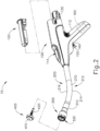
- Stapling head assembly (300) is located at the distal end of shaft assembly (200). As shown in FIGs. 1 and 2 , anvil (400) is configured to removably couple with shaft assembly (200), adjacent to stapling head assembly (300). As will be described in greater detail below, anvil (400) and stapling head assembly (300) are configured to cooperate to manipulate tissue in three ways, including clamping the tissue, cutting the tissue, and stapling the tissue. As best seen in FIGs. 4 and 5 , stapling head assembly (300) of the present example comprises a tubular casing (310) housing a slidable staple driver member (350). A cylindraceous inner core member (312) extends distally within tubular casing (310). Tubular casing (310) is fixedly secured to an outer sheath (210) of shaft assembly (200), such that tubular casing (310) serves as a mechanical ground for stapling head assembly (300).
- Trocar (330) is positioned coaxially within inner core member (312) of tubular casing (310). Trocar (330) is operable to translate distally and proximally relative to tubular casing (310) in response to rotation of a knob (130) located at the proximal end of handle assembly (100).
- Trocar (330) comprises a shaft (332) and a head (334). Head (334) includes a pointed tip (336) and an inwardly extending proximal surface (338). Head (334) and the distal portion of shaft (332) are configured for insertion in bore (422) of anvil (400). Proximal surface (338) is configured to complement features of latch members (430) to provide a snap fit between anvil (400) and trocar (330).
- Staple driver member (350) is operable to actuate longitudinally within tubular casing (310) in response to activation of motor (160) as will be described in greater detail below.
- Staple driver member (350) includes two distally presented concentric annular arrays of staple drivers (352).
- Staple drivers (352) are arranged to correspond with the arrangement of staple forming pockets (414) described above.
- each staple driver (352) is configured to drive a corresponding staple into a corresponding staple forming pocket (414) when stapling head assembly (300) is actuated.
- Staple driver member (350) also defines a bore (354) that is configured to coaxially receive core member (312) of tubular casing (310).
- Knife member (340) is coaxially positioned within staple driver member (350).
- Knife member (340) includes a distally presented, sharp circular cutting edge (342).
- Knife member (340) is sized such that knife member (340) defines an outer diameter that is smaller than the diameter defined by the inner annular array of staple drivers (352).
- Knife member (340) also defines an opening that is configured to coaxially receive core member (312) of tubular casing (310).
- a deck member (320) is fixedly secured to tubular casing (310).
- Deck member (320) includes a distally presented deck surface (322) defining two concentric annular arrays of staple openings (324).
- Staple openings (324) are arranged to correspond with the arrangement of staple drivers (352) and staple forming pockets (414) described above.
- each staple opening (324) is configured to provide a path for a corresponding staple driver (352) to drive a corresponding staple through deck member (320) and into a corresponding staple forming pocket (414) when stapling head assembly (300) is actuated.
- the arrangement of staple openings (324) may be modified just like the arrangement of staple forming pockets (414) as described above.
- Deck member (320) defines an inner diameter that is just slightly larger than the outer diameter defined by knife member (340). Deck member (320) is thus configured to allow knife member (340) to translate distally to a point where cutting edge (342) is distal to deck surface (322).
- FIG. 6 shows various components of shaft assembly (200), which extends distally from handle assembly (100) and couples components of stapling head assembly (300) with components of handle assembly (100).
- shaft assembly (200) includes an outer sheath (210) that extends between handle assembly (100) and tubular casing (310).
- outer sheath (210) is rigid and includes a preformed curved section (212) that is configured to facilitate positioning of stapling head assembly (300) within a patient's colon as described below.
- Curved section (212) includes an inner curve (216) and an outer curve (214).
- Shaft assembly (200) further includes a trocar actuation rod (220) and a trocar actuation band assembly (230).
- the distal end of trocar actuation band assembly (230) is fixedly secured to the proximal end of trocar shaft (332).
- the proximal end of trocar actuation band assembly (230) is fixedly secured to the distal end of trocar actuation rod (220), such that trocar (330) will translate longitudinally relative to outer sheath (210) in response to translation of trocar actuation band assembly (230) and trocar actuation rod (220) relative to outer sheath (210).
- Trocar actuation band assembly (230) is configured to flex such that trocar actuation band assembly (230) may follow along the preformed curve in shaft assembly (200) as trocar actuation band assembly (230) is translated longitudinally relative to outer sheath (210).
- trocar actuation band assembly (230) has sufficient column strength and tensile strength to transfer distal and proximal forces from trocar actuation rod (220) to trocar shaft (332).
- Trocar actuation rod (220) is rigid.
- a clip (222) is fixedly secured to trocar actuation rod (220) and is configured to cooperate with complementary features within handle assembly (100) to prevent trocar actuation rod (220) from rotating within handle assembly (100) while still permitting trocar actuation rod (220) to translate longitudinally within handle assembly (100).
- Trocar actuation rod (220) further includes a coarse helical threading (224) and a fine helical threading (226).
- Shaft assembly (200) further includes a stapling head assembly driver (240) that is slidably received within outer sheath (210).
- the distal end of stapling head assembly driver (240) is fixedly secured to the proximal end of staple driver member (350).
- the proximal end of stapling head assembly driver (240) is secured to a drive bracket (250) via a pin (242). It should therefore be understood that staple driver member (350) will translate longitudinally relative to outer sheath (210) in response to translation of stapling head assembly driver (240) and drive bracket (250) relative to outer sheath (210).
- Stapling head assembly driver (240) is configured to flex such that stapling head assembly driver (240) may follow along the preformed curve in shaft assembly (200) as stapling head assembly driver (240) is translated longitudinally relative to outer sheath (210). However, stapling head assembly driver (240) has sufficient column strength to transfer distal forces from drive bracket (250) to staple driver member (350).
- handle assembly (100) includes a pistol grip (112) and several components that are operable to actuate anvil (400) and stapling head assembly (300).
- handle assembly (100) includes knob (130), a safety trigger (140) a firing trigger (150), a motor (160), and a motor activation module (180).
- Knob (130) is coupled with trocar actuation rod (220) via a nut (not shown), such that coarse helical threading (224) will selectively engage a thread engagement feature within the interior of the nut; and such that fine helical threading (226) will selectively engage a thread engagement feature within the interior of knob (130).
- These complementary structures are configured such that trocar actuation rod (220) will first translate proximally at a relatively slow rate, then translate proximally at a relatively fast rate, in response to rotation of knob (130).
- knob (130) when anvil (400) is coupled with trocar (330), rotation of knob (130) will provide corresponding translation of anvil relative to stapling head assembly (300). It should also be understood that knob (130) may be rotated in a first angular direction (e.g., clockwise) to retract anvil (400) toward stapling head assembly (300); and in a second angular direction (e.g., counterclockwise) to advance anvil (400) away from stapling head assembly (300). Knob (130) may thus be used to adjust the gap distance between opposing surfaces (412, 322) of anvil (400) and stapling head assembly (300) until a suitable gap distance has been achieved.
- first angular direction e.g., clockwise
- a second angular direction e.g., counterclockwise
- handle assembly (100) comprises a user feedback feature (114) that is configured to provide the operator with visual feedback indicating the positioning of anvil (400) in relation to stapling head assembly (300). The operator may thus observe user feedback feature (114) while rotating knob (130), to confirm whether the suitable gap distance between anvil (400) and stapling head assembly (300) has been achieved.
- Firing trigger (150) is operable to activate motor (160) to thereby actuate stapling head assembly (300).
- Safety trigger (140) is operable to selectively block actuation of firing trigger (150) based on the longitudinal position of anvil (400) in relation to stapling head assembly (300).
- Handle assembly (100) also includes components that are operable to selectively lock out both triggers (140, 150) based on the position of anvil (400) relative to stapling head assembly (300). When triggers (140, 150) are locked out, firing trigger (150) is prevented from initiating actuation of stapling head assembly (300).
- trigger (150) is only operable to initiate actuation of stapling head assembly (300) when the position of anvil (400) relative to stapling head assembly (300) is within a predefined range.
- firing trigger (150) of the present example includes an integral actuation paddle.
- the paddle is configured to actuate a switch of motor activation module (180) ( FIG. 1 ) when firing trigger (150) is pivoted to a fired position.
- Motor activation module (180) is in communication with battery pack (120) and motor (160), such that motor activation module (180) is configured to provide activation of motor (160) with electrical power from battery pack (120) in response to the paddle actuating the switch of motor activation module (180).
- motor (160) will be activated when firing trigger (150) is pivoted. This activation of motor (160) will actuate stapling head assembly (300) as described in greater detail below.
- battery pack (120) can consist of battery (122) and battery housing (608).
- the battery housing (608) can be the outer shell of the battery pack (120) that connects to or otherwise engages with handle assembly (see, e.g., FIG. 8 ).
- the battery pack (120) can be inserted into housing cavity (610) within handle assembly (100).
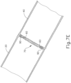
- FIGs. 7A-7E show circular stapler (10) being used to form an anastomosis (70) between two tubular anatomical structures (20, 40).
- the tubular anatomical structures (20, 40) may comprise sections of a patient's esophagus, sections of a patient's colon, other sections of the patient's digestive tract, or any other tubular anatomical structures.
- one or more diseased portions of a patient's colon are removed, with the tubular anatomical structures (20, 40) of FIGs. 7A-7E representing the remaining severed portions of the colon.
- anvil (400) is positioned in one tubular anatomical structure (20) and stapling head assembly (300) is positioned in another tubular anatomical structure (40).
- stapling head assembly (300) may be inserted via the patient's rectum.
- FIGs. 7A-7E is an open surgical procedure, though the procedure may instead be performed laparoscopically. By way of example only, the surgical procedure may be performed laparoscopically.
- circular stapler (10) may be used to form an anastomosis (70) in a laparoscopic procedure will be apparent to those of ordinary skill in the art in view of the teachings herein.
- anvil (400) is positioned in tubular anatomical structure (20) such that shank (420) protrudes from the open severed end (22) of tubular anatomical structure (20).
- a purse-string suture (30) is provided about a mid-region of shank (420) to generally secure the position of anvil (400) in tubular anatomical structure (20).
- stapling head assembly (300) is positioned in tubular anatomical structure (40) such that trocar (330) protrudes from the open severed end (42) of tubular anatomical structure (20).
- a purse-string suture (50) is provided about a mid-region of shaft (332) to generally secure the position of stapling head assembly (300) in tubular anatomical structure (40).
- anvil (400) is secured to trocar (330) by inserting trocar (330) into bore (422) as shown in FIG. 7B .
- Latch members (430) engage head (334) of trocar (330), thereby providing a secure fit between anvil (400) and trocar (330).
- the operator then rotates knob (130) while holding handle assembly (100) stationary via pistol grip (112). This rotation of knob (130) causes trocar (330) and anvil (400) to retract proximally, as described above. As shown in FIG.
- this proximal retraction of trocar (330) and anvil (400) compresses the tissue of tubular anatomical structures (20, 40) between surfaces (412, 322) of anvil (400) and stapling head assembly (300).
- the operator observes user feedback feature (114) to determine whether the gap distance (d) between opposing surfaces (412, 322) of anvil (400) and stapling head assembly (300) is appropriate; and makes any necessary adjustments via knob (130).
- the operator actuates safety trigger (140) to enable actuation of firing trigger (150).
- the operator then actuates firing trigger (150).
- This actuation of firing trigger (150) in turn actuates a switch of motor activation module (180), which in turn activates motor (160) to thereby actuate stapling head assembly (300) by driving knife member (340) and staple driver member (350) distally as shown in FIG. 7D .
- knife member (340) translates distally, cutting edge (342) of knife member (340) cooperates with inner edge (416) of anvil (400), thereby shearing excess tissue that is positioned within annular recess (418) of anvil (400) and the interior of knife member (340).
- anvil (400) of the present example includes a breakable washer (417) within annular recess (418).
- This washer (417) is broken by knife member (340) when knife member (340) completes a full distal range of motion from the position shown in FIG. 7C to the position shown in FIG. 7D .
- the drive mechanism for knife member (340) may provide an increasing mechanical advantage as knife member (340) reaches the end of its distal movement, thereby providing greater force by which to break washer (417).
- breakable washer (417) may be omitted entirely in some versions.
- washer (417) may also serve as a cutting board for knife member (340) to assist in cutting of tissue. Such a cutting technique may be employed in addition to or in lieu of the above- noted shearing action between inner edge (416) and cutting edge (342).
- staple driver member (350) drives staples (90) through the tissue of tubular anatomical structures (20, 40) and into staple forming pockets (414) of anvil (400). Staple forming pockets (414) deform the driven staples (90) into a "B" shape as is known in the art.
- the formed staples (90) thus secure the ends of tissue together, thereby coupling tubular anatomical structure (20) with tubular anatomical structure (40).
- tubular anatomical structures (20, 40) With circular stapler (10) removed, the tubular anatomical structures (20, 40) are left secured together by two annular arrays of staples (90) at an anastomosis (70) as shown in FIG. 7E .
- the inner diameter of the anastomosis (70) is defined by the severed edge (60) left by knife member (340).
- reconfiguring and rearranging staple forming pockets (414) may result in reconfiguration and rearrangement of staples (90) that are formed by staple forming pockets (414).
- the configuration and arrangement of staple forming pockets (414) may affect the structural integrity of an anastomosis (70) that is secured by staples (90).
- the configuration and arrangement of staple forming pockets (414) may affect the hemostasis that is achieved at an anastomosis (70) that is secured by staples (90).
- the following description relates to several exemplary variations of anvil (400), providing staple forming pocket configurations and arrangements that differ from those of staple forming pockets (414).
- Circular stapler (10) described herein can include smart components that generate data and transmit the data to other remote components.
- circular stapler (10) can include a smart anvil (400), as will be described in greater detail with respect to FIG. 17 .
- the anvil (400) can generate signals inside of an operative site, for example data about the location of the anvil (400) (e.g., whether or not anvil (400) is current attached to stapling head assembly (300)) and/or information about the firing of the staples (90), such as the force seen on anvil (400) during the firing process.
- the anvil (400) can transmit data about those signals to outside of the patient.
- FIGs. 8-13B each provide example locations of an antenna or transceiver (e.g., handle transceiver (604)) within a handle assembly (100) that enables signals to be sent close range (yet through tissue) to handle assembly, then long range to an external hub (902) outside of the patient. Additional information about circular staplers can be found in U.S. Publication No. 2018/0132849 , entitled Staple Forming Pocket Configurations For Circular Surgical Stapler Anvil, which is incorporated herein by reference in its entirety.
- handle controller (602) can include hardware and/or software to help control (i.e., generate or receive firing signals to and from stapling head assembly (300) or other components of the circular stapler (10) such as the motor (160)) or monitor the device (i.e., generate or receive information about previous staple firings for the device).
- anvil (400) during operation is positioned inside an obstruction (900) (e.g., the patient's abdomen).
- Anvil (400) can generate said information about the stapling procedure at the distal end of the device within obstruction (900), and relay that information outside of obstruction (900).
- An implementation can be to send that information to external hub (902), which can include an external computing system with a display for providing the information received from within obstruction (900).
- That external hub (902) can be positioned many feet away from the location of circular stapler (10), and since the patient's tissue can obstruct signals in the normal range of operation of such devices (e.g., around 2.4GHz for Bluetooth TM or Wi-Fi TM ), the obstruction may be such that the signals cannot reach hub (902).
- handle transceiver (604) can act as a relay to both (i) receive short-range signals from anvil transceiver (706) and (ii) transmit longer-range signals to hub (902).
- the relay i.e., handle transceiver (604)
- the distal component anvil transceiver (706)
- handle transceiver (604) is placed in handle assembly .
- the designs herein each provide solutions in their own right to improve the wireless connection between handle transceiver (604) and anvil transceiver (706)).
- the controller can be positioned within handle assembly (100).
- handle controller (602) is positioned proximate housing cavity (610) that accepts battery housing (608). Positioning handle controller (602) within handle assembly (100) near the location of battery (122) within battery housing (608) can help to ensure a secure, solid, and direct connection to that power source.
- handle assembly (100) can also include display panel (618) including a display (620), and positioning handle controller (602) on the upper portion of handle assembly (100) enables handle controller (602) to be positioned proximate display panel (618).
- handle assembly (100) acts to receive the signals from anvil (400).
- handle transceiver (604) is positioned close to handle controller (602) to provide a short connection to the controller, and in some instances handle transceiver (604) can be positioned on the same circuit board that comprises handle controller (602).
- the location of handle transceiver (604) in FIG. 8 allows for the transceiver to be positioned on the upper part of handle assembly (100) such that the transceiver has a clear and direct path to anvil (400) positioned within the patient.
- shaft assembly (200) can include preformed curved section (212) that is configured to facilitate positioning of stapling head assembly (300) within the patient's colon, and the curve can help to further align anvil (400) in a direct path, less obstructed to handle transceiver (604).
- handle transceiver (604) is positioned within handle assembly (100) distal to handle controller (602). As such, handle transceiver (604) cannot then be positioned on the same circuit board as handle controller (602), and the communication between the two components can be completed by use of connector (606).
- This connector (606) can be a coaxial cable or the like that enables handle transceiver (604) to be positioned within the center of knob (130) such that knob (130) is able to freely rotate around handle controller (602) itself.
- FIG. 11 depicts circular stapler (10) with handle transceiver (604) positioned within battery housing (608), according to one aspect of the present disclosure.
- battery housing (608) of battery pack (120) may be removably coupled with handle assembly (100) through a snap fit or in any other suitable fashion.
- Battery housing (608) and handle assembly (100) may have complementary electrical contacts, pins and sockets, and/or other features that provide paths for electrical communication between battery pack (120) and handle assembly (100).
- circular stapler (10) can include first connector (614) positioned on the battery housing (608) and which is in electrical communication with handle transceiver (604) that is positioned on or within battery housing (608).
- transceiver also allows for the transceiver to be positioned on the upper part of handle assembly (100) such that the transceiver has a clear and direct path to anvil (400) positioned within the patient.
- shaft assembly (200) can include preformed curved section (212) that is configured to facilitate positioning of stapling head assembly (300) within the patient's colon, and the curve can help to further align anvil (400) in a direct path, less obstructed to handle transceiver (604).
- FIG. 13A depicts circular stapler (10) with handle transceiver (604) positioned on display panel (618), and FIG. 13B provides a detail view of display panel (618), according to one aspect of the present disclosure.
- Display panel (618) can be positioned superficially on the housing of handle assembly (100), at the top of handle assembly (100), and proximate housing cavity (610), as shown.
- Display panel (618) can include display (620) that provides information about circular stapler (10) (e.g., information about the status of firing, information about status of staples (90), etc.).
- Display (620) can be a light-emitting diode (LED), liquid crystal display (LCD), and the like.
- Handle transceiver (604) can be positioned proximate display panel (618).
- a handle transceiver (604) positioned as such can therefore be positioned proximate handle controller (602) so as to provide a short connection to the controller, and in some instances handle transceiver (604) and at least a portion of display (620) can be positioned on the same circuit board that comprises handle controller (602). Further, the location of handle transceiver (604) in FIGs. 13A and 13B allows for the transceiver to be positioned on the upper part of handle assembly (100) such that the transceiver has a clear and direct path to anvil (400) positioned within the patient.
- the position sensors in handle assembly (100) can generate information about its orientation
- the position sensors (712) in anvil (400) can generate information about its orientation
- both sets of information can be relayed to external hub (902) to assist in aligning trocar (330) and lumen (422).
- This information can be generated by position sensor (712), transmitted to processor (704) to be processed, and then transmitted to anvil transceiver (706) to in turn be relayed to handle transceiver (604). Handle transceiver (604) can then send the generated sensor data to external hub (902) to that it can be displayed to the user.
- Anvil (400) can include other types of sensors, as will be described below with respect to FIG. 15 .
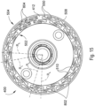
- FIG. 15 shows an exemplary anvil (400) that may be used with a version of circular stapler (10).
- Anvil (400) of the present example comprises anvil surface (412) that defines an inner annular array (502) of staple forming pockets (510) and an outer annular array (504) of staple forming pockets (550) (both similar to aforementioned staple forming pockets (414)).
- staple forming pockets (510, 550) can be arranged such that a radius line (R L ) extending outwardly from the center of anvil (400) passes through the region of entry surface of staple forming pocket (510) and through the region of entry surface of staple forming pocket (550).
- staple forming pockets (510, 550) can overlap along a radial dimension.
- a chamfered edge (508) extends about the outer perimeter of proximal surface (506). It should be understood that anvil (400) may be secured to trocar (330), that proximal surface (506) may be used to compress tissue against deck surface (322), and that staple driver (352) may drive staples (90) through tissue into staple forming pockets (510,550) in order to thereby form staples (90) in the tissue.
- Anvil (400) can include surface sensor (802) positioned on the anvil surface (412).
- Surface sensor (802) is operable to detect contact of tissue upon the anvil surface (412), generate a signal with information related to the contact, transmit the generated signal to processor (704) to be processed, such that the signal can be transmitted to anvil transceiver (706) to in turn be relayed to handle transceiver (604). This information can be used to determine that tissue is properly compressed between anvil surface (412) and distally presented deck surface (322) of stapling head assembly (300) (see FIG. 4 ).
- surface sensor (802) is one of a plurality of surface sensors, and the plurality of surface sensors is configured to detect compression of tissue between anvil surface (412) and the deck surface (322).
- surface sensor (802) can measure tissue impedances at different zones on the anvil surface (412), compare the measured tissue impedances to predetermined tissue impedance signature of the surface sensor (802), and detect an irregularity in at least one of position or orientation of the tissue between the anvil surface (412) and distally presented deck surface (322) of stapling head assembly (300) (see FIG. 4 ).
- the compression through tissue may be determined from an impedance of tissue.
- the impedance Z of tissue may increase or decrease. By applying a voltage V and a current I to the tissue, the impedance Z of the tissue may be determined at various levels of compression.
- Anvil (400) can include a plurality of staple pocket sensors (804), each staple pocket sensor (804) positioned within one of the staple forming pockets (414,510,550). Staple pocket sensors (804) can be configured to detect contact by a staple (90), generate a signal comprising information from one or more of the plurality of staple pocket sensors (804), and transmit the generated signal to processor (704) to be processed, such that the signal can be transmitted to anvil transceiver (706) to in turn be relayed to handle transceiver (604).
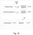
- FIG. 16 is a component diagram of an example smart anvil (400), according to one aspect of the present disclosure.
- anvil (400) can include processor (704), memory (708), and anvil transceiver (706).
- Anvil transceiver (706)-and handle transceiver (604)- can be compatible with one or more of: radio-frequency identification (RFID), near-field communication (NFC), BluetoothTM, low-energy BluetoothTM (BLE), WiFi, or similar technologies.
- RFID radio-frequency identification
- NFC near-field communication
- BLE low-energy BluetoothTM
- WiFi or similar technologies.
- the different components can have different frequencies for different purposes.
- anvil transceiver (706) can transmit a signal at a first frequency
- handle transceiver (604) can transmit a signal at a second, different frequency.
- Anvil transceiver (706) can generate and transmit a lower signal frequency to handle transceiver (604) so that the signal can pass through the patient's tissue more easily; handle transceiver (604) can generate and transmit a higher signal frequency since (i) it is not trying to pass through patient tissue and (ii) it can have a frequency that is dedicated to its communication with the external hub (902) and that is different than the anvil frequency to reduce interference.
- Processor (704) can include one or more of a microprocessor, microcontroller, digital signal processor, co-processor or the like or combinations thereof capable of executing stored instructions and operating upon stored data.
- Memory (708) can include, in some implementations, one or more suitable types of memory (e.g., such as volatile or non-volatile memory, random access memory (RAM), read only memory (ROM), programmable read-only memory (PROM), erasable programmable read-only memory (EPROM), electrically erasable programmable read-only memory (EEPROM), flash memory, and the like), for storing files including an operating system, application programs, executable instructions and data.
- the processing techniques described herein can be implemented as a combination of executable instructions and data stored within memory (708).
- Memory (708) can include instructions that, when executed by processor (704), perform one or more processes consistent with the functionalities disclosed herein. Methods, systems, and articles of manufacture consistent with disclosed embodiments are not limited to separate programs or computers configured to perform dedicated tasks.
- anvil (400) can include memory (708) that can include one or more programs to perform one or more functions of the disclosed embodiments.
- FIG. 17 depicts a system environment for an example circular stapler (10) and external hub (902), according to one aspect of the present disclosure.
- Handle controller (602) can include processor (904), which can be substantially similar to processor (704).
- Handle controller (602) can include memory (906), which can be substantially similar to memory (708).
- external hub (902) can include an external computing system with a display for providing the information received from within obstruction (900). That external hub (902) can be positioned many feet away from the location of circular stapler (10), and since the patient's tissue can obstruct signals in the normal range of operation of such devices (e.g., around 2.4GHz for Bluetooth TM or Wi-Fi TM ), the obstruction may be such that the signals cannot reach hub (902).
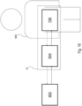
- FIG. 18 is an example schematic of a smart circular stapler (10) in use. It further identifies how anvil transceiver (706) is positioned within obstruction (900) (i.e., the patient's abdomen), handle transceiver (604) is positioned outside of the obstruction (900), and external hub (902) is positioned distal to handle transceiver (604) and circular stapler (10).
- external hub (902) can include an external computing system with a display for providing the information received from within obstruction (900).
- external hub (902) can be a component of a robotic system
- circular stapler (10) can be an attachment to the robotic system.
- distal and proximal are used throughout the preceding description and are meant to refer to a positions and directions relative to the physician or user holding circular stapler 10. As such, “distal” or distally” refer to a position distant to or a direction away from the person gripping circular stapler 10. Similarly, “proximal” or “proximally” refer to a position near or a direction towards the person grasping pistol grip 112 (i.e., toward an operator of circular stapler 10). Furthermore, the singular forms “a,” “an,” and “the” include plural referents unless the context clearly dictates otherwise. Furthermore, the use of “couple”, “coupled”, or similar phrases should not be construed as being limited to a certain number of components or a particular order of components unless the context clearly dictates otherwise.
- the terms “about” or “approximately” for any numerical values or ranges indicate a suitable dimensional tolerance that allows the part or collection of components to function for its intended purpose as described herein. More specifically, “about” or “approximately” may refer to the range of values ⁇ 10% of the recited value, e.g., “about 90%” may refer to the range of values from 80.001% to 99.999%.
Landscapes
- Health & Medical Sciences (AREA)
- Life Sciences & Earth Sciences (AREA)
- Surgery (AREA)
- Heart & Thoracic Surgery (AREA)
- Engineering & Computer Science (AREA)
- Biomedical Technology (AREA)
- Nuclear Medicine, Radiotherapy & Molecular Imaging (AREA)
- Medical Informatics (AREA)
- Molecular Biology (AREA)
- Animal Behavior & Ethology (AREA)
- General Health & Medical Sciences (AREA)
- Public Health (AREA)
- Veterinary Medicine (AREA)
- Surgical Instruments (AREA)
Applications Claiming Priority (1)
| Application Number | Priority Date | Filing Date | Title |
|---|---|---|---|
| US18/394,795 US12336714B1 (en) | 2023-12-22 | 2023-12-22 | Wireless arrays for surgical staplers |
Publications (2)
| Publication Number | Publication Date |
|---|---|
| EP4574060A2 true EP4574060A2 (de) | 2025-06-25 |
| EP4574060A3 EP4574060A3 (de) | 2025-08-20 |
Family
ID=93926135
Family Applications (1)
| Application Number | Title | Priority Date | Filing Date |
|---|---|---|---|
| EP24222602.5A Pending EP4574060A3 (de) | 2023-12-22 | 2024-12-20 | Drahtlose arrays für chirurgische klammergeräte |
Country Status (3)
| Country | Link |
|---|---|
| US (1) | US12336714B1 (de) |
| EP (1) | EP4574060A3 (de) |
| CN (1) | CN120189181A (de) |
Citations (1)
| Publication number | Priority date | Publication date | Assignee | Title |
|---|---|---|---|---|
| US20180132849A1 (en) | 2016-11-14 | 2018-05-17 | Ethicon Endo-Surgery, Llc | Staple forming pocket configurations for circular surgical stapler anvil |
Family Cites Families (15)
| Publication number | Priority date | Publication date | Assignee | Title |
|---|---|---|---|---|
| US8459525B2 (en) * | 2008-02-14 | 2013-06-11 | Ethicon Endo-Sugery, Inc. | Motorized surgical cutting and fastening instrument having a magnetic drive train torque limiting device |
| US9179912B2 (en) * | 2008-02-14 | 2015-11-10 | Ethicon Endo-Surgery, Inc. | Robotically-controlled motorized surgical cutting and fastening instrument |
| US8657174B2 (en) * | 2008-02-14 | 2014-02-25 | Ethicon Endo-Surgery, Inc. | Motorized surgical cutting and fastening instrument having handle based power source |
| US20140249557A1 (en) | 2013-03-01 | 2014-09-04 | Ethicon Endo-Surgery, Inc. | Thumbwheel switch arrangements for surgical instruments |
| MX364729B (es) * | 2013-03-01 | 2019-05-06 | Ethicon Endo Surgery Inc | Instrumento quirúrgico con una parada suave. |
| AU2017250206B2 (en) * | 2016-04-12 | 2022-03-24 | Applied Medical Resources Corporation | Surgical stapler having a powered handle |
| US20180326144A1 (en) * | 2017-05-12 | 2018-11-15 | Meditrina, Inc. | Endoscope system and method of use |
| US11510741B2 (en) * | 2017-10-30 | 2022-11-29 | Cilag Gmbh International | Method for producing a surgical instrument comprising a smart electrical system |
| US11109866B2 (en) * | 2017-12-28 | 2021-09-07 | Cilag Gmbh International | Method for circular stapler control algorithm adjustment based on situational awareness |
| US10702349B2 (en) * | 2018-02-20 | 2020-07-07 | Ethicon Llc | Robotic surgical instrument communication |
| US11490891B2 (en) * | 2020-07-10 | 2022-11-08 | Cilag Gmbh International | Load sensor for circular surgical stapler |
| US20220104820A1 (en) * | 2020-10-02 | 2022-04-07 | Ethicon Llc | Surgical instrument with adaptive motor control |
| US20220233241A1 (en) * | 2021-01-22 | 2022-07-28 | Ethicon Llc | Surgical procedure monitoring |
| US11749877B2 (en) | 2021-02-26 | 2023-09-05 | Cilag Gmbh International | Stapling instrument comprising a signal antenna |
| US12432790B2 (en) * | 2021-10-28 | 2025-09-30 | Cilag Gmbh International | Method and device for transmitting UART communications over a security short range wireless communication |
-
2023
- 2023-12-22 US US18/394,795 patent/US12336714B1/en active Active
-
2024
- 2024-12-20 EP EP24222602.5A patent/EP4574060A3/de active Pending
- 2024-12-20 CN CN202411886874.1A patent/CN120189181A/zh active Pending
Patent Citations (1)
| Publication number | Priority date | Publication date | Assignee | Title |
|---|---|---|---|---|
| US20180132849A1 (en) | 2016-11-14 | 2018-05-17 | Ethicon Endo-Surgery, Llc | Staple forming pocket configurations for circular surgical stapler anvil |
Also Published As
| Publication number | Publication date |
|---|---|
| CN120189181A (zh) | 2025-06-24 |
| US12336714B1 (en) | 2025-06-24 |
| EP4574060A3 (de) | 2025-08-20 |
| US20250204914A1 (en) | 2025-06-26 |
Similar Documents
| Publication | Publication Date | Title |
|---|---|---|
| EP3320858B1 (de) | Ringförmiges, chirurgisches klammergerät mit versenktem verdeck | |
| EP3320859B1 (de) | Ringförmiges, chirurgisches klammergerät mit winkelig asymmetrischen verdecksmerkmalen | |
| US20220110630A1 (en) | Staple forming pocket configurations for circular surgical stapler anvil | |
| EP2305139B1 (de) | Elektromechanische antriebsvorrichtung und ferngesteuerter chirurgischer gerätevorsatz mit computergestützten steuerungmöglichkeiten | |
| US7077856B2 (en) | Electromechanical driver and remote surgical instrument attachment having computer assisted control capabilities | |
| JP7571129B2 (ja) | 動力付き円形外科用ステープラのためのアンビル保持及び解放機構 | |
| JP2005511131A (ja) | 手術用装置 | |
| JP2018519066A (ja) | 不完全発射インジケータを有する外科用ステープラー | |
| US11490891B2 (en) | Load sensor for circular surgical stapler | |
| US12336714B1 (en) | Wireless arrays for surgical staplers | |
| US20250235214A1 (en) | Locally powered stapler anvil with contact indicator | |
| EP4548863A1 (de) | Intelligenter amboss für kreisförmiges chirurgisches klammergerät | |
| EP4497396A2 (de) | Unabhängig betriebener amboss für kreisförmiges chirurgisches klammergerät | |
| US20250204910A1 (en) | Surgical staplers with removable and reusable control attachments |
Legal Events
| Date | Code | Title | Description |
|---|---|---|---|
| PUAI | Public reference made under article 153(3) epc to a published international application that has entered the european phase |
Free format text: ORIGINAL CODE: 0009012 |
|
| STAA | Information on the status of an ep patent application or granted ep patent |
Free format text: STATUS: THE APPLICATION HAS BEEN PUBLISHED |
|
| AK | Designated contracting states |
Kind code of ref document: A2 Designated state(s): AL AT BE BG CH CY CZ DE DK EE ES FI FR GB GR HR HU IE IS IT LI LT LU LV MC ME MK MT NL NO PL PT RO RS SE SI SK SM TR |
|
| PUAL | Search report despatched |
Free format text: ORIGINAL CODE: 0009013 |
|
| AK | Designated contracting states |
Kind code of ref document: A3 Designated state(s): AL AT BE BG CH CY CZ DE DK EE ES FI FR GB GR HR HU IE IS IT LI LT LU LV MC ME MK MT NL NO PL PT RO RS SE SI SK SM TR |
|
| RIC1 | Information provided on ipc code assigned before grant |
Ipc: A61B 17/115 20060101AFI20250714BHEP Ipc: A61B 17/00 20060101ALN20250714BHEP |
|
| STAA | Information on the status of an ep patent application or granted ep patent |
Free format text: STATUS: REQUEST FOR EXAMINATION WAS MADE |
|
| 17P | Request for examination filed |
Effective date: 20260220 |